US8821379B2 - Industrial endoscope apparatus - Google Patents
Industrial endoscope apparatus Download PDFInfo
- Publication number
- US8821379B2 US8821379B2 US13/528,313 US201213528313A US8821379B2 US 8821379 B2 US8821379 B2 US 8821379B2 US 201213528313 A US201213528313 A US 201213528313A US 8821379 B2 US8821379 B2 US 8821379B2
- Authority
- US
- United States
- Prior art keywords
- display
- image
- endoscope apparatus
- superimposition information
- user interface
- Prior art date
- Legal status (The legal status is an assumption and is not a legal conclusion. Google has not performed a legal analysis and makes no representation as to the accuracy of the status listed.)
- Active, expires
Links
Images


Classifications
-
- A—HUMAN NECESSITIES
- A61—MEDICAL OR VETERINARY SCIENCE; HYGIENE
- A61B—DIAGNOSIS; SURGERY; IDENTIFICATION
- A61B1/00—Instruments for performing medical examinations of the interior of cavities or tubes of the body by visual or photographical inspection, e.g. endoscopes; Illuminating arrangements therefor
- A61B1/00002—Operational features of endoscopes
- A61B1/00039—Operational features of endoscopes provided with input arrangements for the user
- A61B1/00042—Operational features of endoscopes provided with input arrangements for the user for mechanical operation
-
- A—HUMAN NECESSITIES
- A61—MEDICAL OR VETERINARY SCIENCE; HYGIENE
- A61B—DIAGNOSIS; SURGERY; IDENTIFICATION
- A61B1/00—Instruments for performing medical examinations of the interior of cavities or tubes of the body by visual or photographical inspection, e.g. endoscopes; Illuminating arrangements therefor
- A61B1/00002—Operational features of endoscopes
- A61B1/00043—Operational features of endoscopes provided with output arrangements
- A61B1/00045—Display arrangement
- A61B1/0005—Display arrangement combining images e.g. side-by-side, superimposed or tiled
-
- A—HUMAN NECESSITIES
- A61—MEDICAL OR VETERINARY SCIENCE; HYGIENE
- A61B—DIAGNOSIS; SURGERY; IDENTIFICATION
- A61B1/00—Instruments for performing medical examinations of the interior of cavities or tubes of the body by visual or photographical inspection, e.g. endoscopes; Illuminating arrangements therefor
- A61B1/00002—Operational features of endoscopes
- A61B1/00043—Operational features of endoscopes provided with output arrangements
- A61B1/00045—Display arrangement
- A61B1/00052—Display arrangement positioned at proximal end of the endoscope body
-
- G—PHYSICS
- G02—OPTICS
- G02B—OPTICAL ELEMENTS, SYSTEMS OR APPARATUS
- G02B23/00—Telescopes, e.g. binoculars; Periscopes; Instruments for viewing the inside of hollow bodies; Viewfinders; Optical aiming or sighting devices
- G02B23/24—Instruments or systems for viewing the inside of hollow bodies, e.g. fibrescopes
- G02B23/2476—Non-optical details, e.g. housings, mountings, supports
- G02B23/2484—Arrangements in relation to a camera or imaging device
Definitions
- the present invention relates to an endoscope apparatus, and a method of displaying images.
- Priority is claimed on Japanese Patent Application No. 2011-208012, filed on Sep. 22, 2011, the content of which is incorporated herein by reference.
- industrial endoscope apparatuses are known (for example, see Japanese Unexamined Patent Application, First Publication No. 2009-089955).
- endoscope apparatuses provided with an image rotation function capable of rotating and displaying an endoscopic image and an OSD (on-screen display) on the display portion for ease of inspection even if the endoscope apparatuses are used in the inverted orientation.
- endoscope apparatuses are known in which the operation portion and the display portion are arranged in the same housing (all-in-one endoscope apparatuses).
- an endoscope apparatus includes: an insertion portion configured to include a bend portion; an image pickup portion configured to capture an image of an object to be inspected; an operation portion configured to perform a bending operation of the bend portion; a storage portion configured to store at least an image of the objected to be inspected as a recorded image; a display portion configured to display the image, the display portion having a fixed positional relationship relative to the operation portion; and a display control portion configured to: determine a display orientation of a superimposition information, the superimposition information being superimposed on the image; display the image captured by the image pickup portion without rotating the image; and display the superimposition information according to the display orientation of the superimposition information, the display control portion being further configured to: determine a display orientation of at least one of the recorded image and a Graphical User Interface; and display the at least one of the recorded image and the Graphical User Interface according to the display orientation of the at least one of the recorded image and the Graphical User Interface.
- FIG. 1 is an overall perspective view showing an appearance of an endoscope apparatus according to one embodiment of the present invention.
- FIG. 2 is a block diagram showing a configuration of the endoscope apparatus of the embodiment.
- FIG. 3 is a front view showing the appearance of the endoscope apparatus of the embodiment when the orientation of the endoscope apparatus is inverted.
- FIG. 4 is a side view showing the appearance of the endoscope apparatus of the embodiment when the orientation of the endoscope apparatus is inverted.
- FIG. 5A is a schematic diagram showing an example where a display control portion displays, on a display portion, an image captured by an image pickup portion and OSDs in a non-rotated state in the embodiment.
- FIG. 5B is a schematic diagram showing an example where the display control portion displays, on the display portion, the image captured by an image pickup portion and the OSDs in the non-rotated state in the embodiment.
- FIG. 6A is a schematic diagram showing an example where the display control portion displays, on the display portion, the image captured by an image pickup portion in the non-rotated state, and the OSDs in an rotated state.
- FIG. 6B is a schematic diagram showing an example where the display control portion displays, on the display portion, the image captured by the image pickup portion in the non-rotated state, and the OSDs in the rotated state.
- FIG. 7A is a schematic diagram showing an example where the display control portion displays, on the display portion, a recorded image stored by a storage portion and GUI such as a menu screen in the rotated state in the embodiment.
- FIG. 7B is a schematic diagram showing an example where the display control portion displays, on the display portion, the recorded image stored by the storage portion and the GUI such as a menu screen in the rotated state in the embodiment.
- FIG. 8 is a flow chart showing an operation procedure of a capturing operation of the endoscope apparatus according to the embodiment.
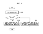
- FIG. 9 is a flow chart showing an operation procedure of a playback operation of the endoscope apparatus according to the embodiment.
- FIG. 10A is a schematic diagram showing an example where the display control portion displays, on the display portion, the image captured by the image pickup portion in the non-rotated state, and the OSDs in a left side rotated state in the embodiment.
- FIG. 10B is a schematic diagram showing an example where the display control portion displays, on the display portion, the image captured by the image pickup portion in the non-rotated state, and the OSDs in a right side rotated state in the embodiment.
- FIG. 11A is a schematic diagram showing an example where the display control portion displays, on the display portion, a recorded image stored by a storage portion and GUI such as a menu screen in a left side rotated state in the embodiment.
- FIG. 11B is a schematic diagram showing an example where the display control portion displays, on the display portion, a recorded image stored by a storage portion and GUI such as a menu screen in a right side rotated state in the embodiment.
- FIG. 1 is an overall perspective view showing an appearance of an endoscope apparatus in the present embodiment.
- the endoscope apparatus 1 of the present embodiment is used for observing an inspection target located at the end of an elongated insertion channel, an internal portion of the inspection target, and the like.
- the endoscope apparatus 1 includes: an insertion portion 10 ; an operation portion 21 for performing a bending operation of the insertion portion 10 ; a display portion 25 for displaying a video picture obtained by the insertion portion 10 ; and a housing portion 60 for containing the operation portion 21 and the display portion 25 .
- FIG. 2 is a block diagram showing a configuration of the endoscope apparatus 1 of the present embodiment.
- the housing portion 60 of the endoscope apparatus 1 includes an operation portion 21 ; a control portion 22 ; an image processing portion 23 ; a display control portion 24 ; a display portion 25 ; and a storage portion 26 .
- the image pickup portion 11 , the illumination portion 12 , and the operation portion 21 are constructed as described above.
- the control portion 22 controls the constituent elements included in the endoscope apparatus 1 .
- the image processing portion 23 performs image processing on an image captured by the image pickup portion 11 .
- the display control portion 24 controls the display portion 25 , and causes the display portion 25 to display an image of an inspection target.
- the display portion 25 includes a display such as a LCD (Liquid Crystal Display), and displays an image through control by the display control portion 24 .
- the storage portion 26 stores: the images captured by the image pickup portion 11 ; and the information necessary to the operations of the constituent elements included in the endoscope apparatus 1 .
- the endoscope apparatus 1 is oriented so that the display portion 25 is above the operation portion 21 .
- the control portion 22 generates a signal indicating that a position of the endoscope apparatus 1 is the correctly directed position.
- the insertion portion 10 includes an image pickup portion 11 and an illumination portion 12 at its distal end.
- the image pickup portion 11 includes an image pickup element such as a CCD (Charge Coupled Device).
- the image pickup portion 11 is capable of obtaining an image such as a still image and/or a streaming image of an inspection target or the like ahead of the distal end portion.
- the illumination portion 12 includes an LED (Light Emitting Diode) or the like. The illumination portion 12 emits light ahead of the distal end portion.
- the insertion portion 10 further includes a bend portion 13 in which a plurality of knot rings or bender pieces (not shown in the figure and hereinafter referred to generically as “knot rings or the like”) are aligned in the axis line direction of the insertion portion 10 and connected to each other.
- the insertion portion 10 is capable of bending in four directions in two axes that cross its central axis line, so as to be spaced away from the central axis line.
- Four operation members such as wires corresponding to the aforementioned four directions are connected to the knot ring or the like closest to the distal end out of all the knot rings or the like.
- the operation members extend through the knot rings or the like to the inside of the housing portion 60 , and are connected to the operation portion 21 there.
- the operation portion 21 includes: a first joy stick 211 for operating the bend portion 13 ; a second joy stick 212 for operating a cursor or the like that is displayed on the display portion 25 ; and a bending mechanism that is operated via the first joy stick 211 .
- the operation portion 21 (the first joy stick 211 ) of the present embodiment employs a mechanical mechanism in which the bend portion 13 is bent by pulling the operation members through an inclining operation.
- the operation portion 21 (the first joy stick 211 ) may employ an electrical mechanism of pulling the operation members by use of a drive device such as a motor in accordance with electrically-detected inclination amount and inclination direction, to thereby operate the bend portion 13 .
- FIG. 3 is a front view showing an appearance of the endoscope apparatus 1 of the present embodiment when the endoscope apparatus 1 is inverted (when the display portion 25 is placed upside down).
- FIG. 4 is a side view showing the appearance of the endoscope apparatus 1 when the endoscope apparatus 1 of the present embodiment is inverted.
- the endoscope apparatus 1 has the display portion 25 placed upside down, and hence, in the position where the operation portion 21 is above the display portion 25 .
- the control portion 22 When the user operates the endoscope apparatus 1 in this position, it is defined that the user operates the endoscope apparatus 1 in an oppositely directed position.
- the control portion 22 generates a signal indicating that a position of the endoscope apparatus 1 is the oppositely directed position.
- FIG. 5A and FIG. 5B are schematic diagram showing an example where the display control portion 24 causes the display portion 25 to display an image captured by the image pickup portion 11 and to display an OSD (On-Screen Display) in a non-rotated state (a state displaying an image, an OSD, or the like without being rotated).
- FIG. 6A and FIG. 6B are schematic diagrams showing an example where the display control portion 24 causes the display portion 25 to display the image captured by the image pickup portion 11 in the non-rotated state and to display the OSD in a rotated state (approximately turned 180 degrees).
- the image captured by the image pickup portion 11 includes a streaming image and/or a still image.
- a streaming image is a realtime image being captured by the image pickup portion 11 .
- a still image is a paused image of a streaming image.
- An OSD includes date, time, and/or additional information (superimposition information) that are superimposed on the image displayed on the display portion 25 .
- FIG. 5A is a schematic diagram of an example where the display control portion 24 causes the display portion 25 to display the image captured by the image pickup portion 11 and to display the OSD when the user is operating the endoscope apparatus 1 in the correctly directed position.
- the user operates the endoscope apparatus 1 in the correctly directed position, and the display control portion 24 causes the display portion 25 to display an image 501 captured by the image pickup portion 11 and to display OSDs 502 in the non-rotated state.
- the direction of the operation on the operation portion 21 by the user coincides with the direction in which the image 501 displayed on the screen moves by the bend portion 13 being bent.
- the user can read the letters on the OSDs 502 in the non-rotated state. Accordingly, the user is capable of easily performing a bending operation of the bend portion 13 .
- FIG. 5B is a schematic diagram showing an example where the display control portion 24 causes the display portion 25 to display the image captured by the image pickup portion 11 and to display the OSD in the non-rotated state when the user is operating the endoscope apparatus 1 in the oppositely directed position.
- the user operates the endoscope apparatus 1 in the oppositely directed position, and the display control portion 24 causes the display portion 25 to display an image 501 captured by the image pickup portion 11 and to display OSDs 502 in the non-rotated state.
- the direction of the operation on the operation portion 21 by the user coincides with the direction in which the image 501 displayed on the screen moves by the bend portion 13 being bent.
- the letters on the OSDs 502 look rotated at 180 degrees for the user.
- FIG. 6A and FIG. 6B are diagrams showing an example where the display control portion 24 causes the display portion 25 to display the image captured by the image pickup portion 11 in the non-rotated state and to display the OSDs in the rotated state (substantially turned 180 degrees).
- the exemplary illustrations in FIG. 6A and FIG. 6B show the case where the user is capable of easily checking the OSD and also of easily performing an bending operation of the bend portion 13 when operating the endoscope apparatus 1 in the correctly directed position. The detailed description is as follows. FIG.
- 6A is a schematic diagram showing an example where the display control portion 24 causes the display portion 25 to display the image 501 captured by the image pickup portion 11 in the non-rotated state and to display the OSDs 502 in the rotated state when the user is operating the endoscope apparatus 1 in the correctly directed position.
- the user operates the endoscope apparatus 1 in the correctly directed position, and the display control portion 24 causes the display portion 25 to display the image 501 captured by the image pickup portion 11 in the non-rotated state and to display the OSDs 502 in the rotated state.
- the direction of the operation on the operation portion 21 by the user coincides with the direction in which the image 501 displayed on the screen moves by the bend portion 13 being bent.
- the letters on the OSDs 502 look rotated at 180 degrees for the user. Therefore, there is a possibility that the use is not capable of easily checking the OSDs 502 .
- FIG. 6B is a schematic diagram of an example where the display control portion 24 causes the display portion 25 to display the image captured by the image pickup portion 11 in the non-rotated state and to display the OSDs in the rotated state when the user is operating the endoscope apparatus 1 in the oppositely directed position.
- the user operates the endoscope apparatus 1 in the oppositely directed position, and the display control portion 24 causes the display portion 25 to display the image 501 captured by the image pickup portion 11 in the non-rotated state and to display the OSDs 502 in the rotated state.
- the direction of the operation on the operation portion 21 by the user coincides with the direction in which the image 501 displayed on the screen moves by the bend portion 13 being bent.
- the user is capable of looking at the letters on the OSDs 502 even if the user operates the endoscope apparatus 1 in the oppositely directed position.
- the direction of the operation on the operation portion 21 by the user is not opposite to the direction in which the image 501 displayed on the screen moves. Therefore, the user is capable of easily checking the OSDs 502 and is also capable of easily performing a bending operation of the bend portion 13 .
- the display control portion 24 causes the display portion 25 to display the image 501 captured by the image pickup portion 11 and to display the OSDs 502 in the non-rotated state. In this case, the user easily checks the OSDs 502 and also performs an bending operation of the bend portion 13 .
- the display control portion 24 causes the display portion 25 to display the image 501 captured by the image pickup portion 11 in the non-rotated state and to display the OSDs 502 in the rotated state. Therefore, the user easily checks the OSDs 502 and performs a bending operation of the bend portion 13 .
- the display control portion 24 causes the display portion 25 to display the image captured by the image pickup portion 11 and to display the OSDs in the non-rotated state in a normal mode in which the user uses the endoscope apparatus 1 in the correctly directed position. Additionally, the display control portion 24 causes the display portion 25 to display the image captured by the image pickup portion 11 in the non-rotated state and to display the OSDs in the rotated state in a rotated display mode in which user uses the endoscope apparatus 1 in the oppositely directed position (the position where the display portion 25 is placed upside down).
- FIG. 7A and FIG. 7B are schematic diagrams showing an example where the display control portion 24 causes the display portion 25 to display the recorded image stored by the storage portion 26 and to display a GUI (Graphical User Interface) such as a menu screen in the rotated state.
- the recorded image stored by the storage portion 26 is a still image in which OSDs are superimposed on the image captured by the image pickup portion 11 .
- the recorded image is not limited to only a single image as shown in FIG. 7A and FIG. 7B , but includes a thumbnail image in which the display control portion 24 causes the display portion 25 to display a plurality of scaled-down recorded images on a single screen.
- FIG. 7A is a schematic diagram of an example where the display control portion 24 causes the display portion 25 to display recorded images 701 stored by the storage portion 26 and to display a GUI 702 in the rotated state when the user is operating the endoscope apparatus 1 in the correctly directed position.
- the user operates the endoscope apparatus 1 in the correctly directed position, and the display control portion 24 causes the display portion 25 to display the recorded images 701 stored by the storage portion 26 and to display the GUI 702 in the rotated state.
- the recorded images 701 and the GUI 702 look rotated at 180 degrees for the user. Therefore, there is a possibility that the use is not capable of easily checking the recorded image and the GUI.
- FIG. 7B is a schematic diagram of an example where the display control portion 24 causes the display portion 25 to display the recorded images 701 stored by the storage portion 26 and to display the GUI 702 in the rotated state when the user is operating the endoscope apparatus 1 in the oppositely directed position.
- the user operates the endoscope apparatus 1 in the oppositely directed position, and the display control portion 24 causes the display portion 25 to display the recorded images 701 stored by the storage portion 26 and to display the GUI 702 in the rotated state.
- the user is capable of looking at the recorded images 701 and the GUI 702 even if the user operates the endoscope apparatus 1 in the oppositely directed position. Therefore, the user is capable of easily checking the recorded image and the GUI.
- the display control portion 24 causes the display portion 25 to display the recorded images 701 stored by the storage portion 26 and to display the GUI 702 in the non-rotated state. In this case, the user is capable of easily checking the recorded image and the GUI.
- the display control portion 24 causes the display portion 25 to display the recorded images 701 stored by the storage portion 26 and to display the GUI 702 in the rotated state. In this case, the user is capable of easily checking the recorded image and the GUI.
- the display control portion 24 causes the display portion 25 to display the recorded image stored by the storage portion 26 and to display the GUI in the non-rotated state in playing back the recorded image stored by the storage portion 26 in the normal mode in which user uses the endoscope apparatus 1 in the correctly directed position. Additionally, the display control portion 24 causes the display portion 25 to display the recorded image stored by the storage portion 26 and to display the GUI in the rotated state in playing back the recorded image stored by the storage portion 26 in the rotated display mode in which user uses the endoscope apparatus 1 in the oppositely directed position.
- the display control portion 24 causes the display portion 25 to display the recorded image stored by the storage portion 26 and to display the GUI in the rotated state in playing back the recorded image stored by the storage portion 26 in the rotated display mode in which user uses the endoscope apparatus 1 in the oppositely directed position.
- the display control portion 24 may cause the display portion 25 to display the image 501 in the non-rotated state and to display the GUI 702 in the rotated state.
- FIG. 8 is a flow chart showing an operation procedure of a capturing operation of the endoscope apparatus 1 .
- the user operates a second joy stick 212 included in the operation portion 21 and sets the operation mode of the endoscope apparatus 1 in accordance with the direction in which the endoscope apparatus 1 is operated (used).
- the endoscope apparatus 1 sets the operation mode based on an input that the second joy stick 212 has received.
- the user sets the operation mode of the endoscope apparatus 1 to the normal mode.
- the user sets the operation mode of the endoscope apparatus 1 to the rotated display mode.
- Step S 101 The image pickup portion 11 captures an image. Subsequently, the image processing portion 23 performs image processing on the image captured by the image pickup portion 11 . Subsequently, the display control portion 24 obtains the image on which the image processing portion 23 has performed the image processing. After that, the process moves to step S 102 .
- Step S 102 The control portion 22 determines whether the operation mode of the endoscope apparatus 1 is the rotated display mode or not. If the control portion 22 determines that the operation mode of the endoscope apparatus 1 is the rotated display mode, the process moves to Step S 104 . Otherwise, the process moves to Step S 103 .
- Step S 103 The display control portion 24 causes the display portion 25 to display the image, which has been obtained in Step S 101 , and to display the OSD in the non-rotated state.
- the display control portion 24 produces a non-rotated OSD and a rotated OSD, and stores them in buffer memory (not shown in the figures).
- the display control portion 24 then causes the display portion 25 to display the non-rotated OSD stored in the buffer memory. After that, the process moves to Step S 105 .
- Step S 104 The display control portion 24 causes the display portion 25 to display the image, which has been obtained in Step S 101 , in the non-rotated state, and to display the OSD in the rotated state.
- the display control portion 24 causes the display portion 25 to display the rotated OSD, which has been stored in the buffer memory. After that, the process moves to Step S 105 .
- Step S 105 If the user intends to record the image that has been captured by the image pickup portion 11 and is displayed on the display portion 25 , then the user operates the second joy stick 212 included in the operation portion 21 to input a recording instruction to the endoscope apparatus 1 .
- the control portion 22 determines whether the recording instruction has been received or not. If the control portion 22 determines that the recording instruction has been received, then the process moves to Step S 106 . Otherwise, the process returns to Step S 101 .
- Step S 106 The image processing portion 23 superimposes the OSD in the non-rotated state on the image which has been subjected to the image processing in Step S 101 , and causes the storage portion 26 to store the resultant image as a recorded image. After that, the process returns to Step S 101 . As a result, the OSD in the non-rotated state is superimposed on the recorded image. Therefore, if the image is played back by a PC (Personal Computer) or the endoscope apparatus 1 in the correctly directed position, then the OSD is displayed in the non-rotated state.
- PC Personal Computer
- FIG. 9 is a flow chart showing an operation procedure of a playback operation of the endoscope apparatus 1 .
- the user operates the second joy stick 212 included in the operation portion 21 to set the operation mode of the endoscope apparatus 1 in accordance with the position (the correctly directed position or the oppositely directed position) in which the endoscope apparatus 1 is operated (used). Based on the input received by the second joy stick 212 , the endoscope apparatus 1 sets the operation mode.
- Step S 201 The display control portion 24 reads a recorded image, which is an image to be played back (a playback image), from the storage portion 53 . After that, the process moves to Step S 202 .
- Step S 202 The control portion 22 determines whether the operation mode of the endoscope apparatus 1 is the rotated display mode or not. If the control portion 22 determines that the operation mode of the endoscope apparatus 1 is the rotated display mode, then the process moves to Step S 204 . Otherwise, the process moves to Step S 203 .
- Step S 203 The display control portion 24 causes the display portion 25 to display the recorded image having been read in Step S 201 and to display the GUI (the menu screen) in the non-rotated state.
- Step S 204 The display control portion 24 causes the display portion 25 to display the recorded image which has been read in Step S 201 and to display the GUI (the menu screen) in the rotated state. After that, the process is terminated.
- the display control portion 24 causes the display portion 25 to display the image captured by the image pickup portion 11 and to display the OSD in the non-rotated state when an image captured by the image pickup portion 11 is displayed in the normal mode in which user uses the endoscope apparatus 1 in the correctly directed position.
- the display control portion 24 causes the display portion 25 to display the image captured by the image pickup portion 11 in the non-rotated state and to display the OSD in the rotated state.
- the display control portion 24 causes the display portion 25 to display the recorded image stored by the storage portion 26 and to display the GUI in the non-rotated state when the recorded image stored by the storage portion 26 is played back in the normal mode in which user uses the endoscope apparatus 1 in the correctly directed position.
- the display control portion 24 causes the display portion 25 to display the recorded image stored by the storage portion 26 and to display the GUI in the rotated state when the recorded image stored by the storage portion 26 is played back in the rotated display mode in which user uses the endoscope apparatus 1 in the oppositely directed position.
- the description has been for the case of the endoscope apparatus 1 in which the operation portion 21 and the display portion 25 are arranged in the same housing, by way of example.
- the operation portion 21 and the display portion 25 may be arranged in different housings.
- the description has been for the case where, in the rotated display mode, the images are rotated 180 degrees, by way of example.
- the images may be rotated at every 90 degrees or the like.
- FIG. 10A is a schematic diagram showing an example where the display control portion 24 causes the display portion 25 to display the image when the user operates the endoscope apparatus 1 being rotated at 90 degrees in the clockwise direction in FIG. 10A (a right side directed position) to an arrangement shown in FIG. 5A .
- the display control portion 24 causes the display portion 25 to display the image captured by the image pickup portion 11 in a non-rotated state.
- the display control portion 24 causes the display portion 25 to display the OSD in a state of the OSD being rotated at approximately 90 degrees in the counterclockwise direction in the display portion 25 (a left side rotated state) to an arrangement shown in FIG. 5A .
- the user operates the endoscope apparatus 1 in the right side directed position, and the display control portion 24 causes the display portion 25 to display an image 501 captured by the image pickup portion 11 in the non-rotated state and to display an OSD 502 in the left side rotated state.
- the direction of the operation on the operation portion 21 by the user coincides with the direction in which the image 501 displayed on the screen moves by the bend portion 13 being bent.
- the user can read the letters on the OSD 502 even if the user operates the endoscope apparatus 1 in the right side directed position. Accordingly, the user is capable of easily performing a bending operation of the bend portion 13 .
- FIG. 10B is a schematic diagram showing an example where the display control portion 24 causes the display portion 25 to display an image when the user operates the endoscope apparatus 1 being rotated at 90 degrees in the counterclockwise direction in FIG. 10B (a left side directed position) to an arrangement shown in FIG. 5A .
- the display control portion 24 causes the display portion 25 to display the image captured by the image pickup portion 11 in the non-rotated state.
- the display control portion 24 causes the display portion 25 to display an OSD being rotated at approximately 90 degrees in the clockwise direction in the display portion 25 (a right side rotated state) to an arrangement shown in FIG. 5A .
- the user operates the endoscope apparatus 1 in the left side directed position, and the display control portion 24 causes the display portion 25 to display an image 501 captured by the image pickup portion 11 in the non-rotated state and to display an OSD 502 in the right side rotated state.
- the direction of the operation on the operation portion 21 by the user coincides with the direction in which the image 501 displayed on the screen moves by the bend portion 13 being bent.
- the user can read the letters on the OSD 502 even if the user operates the endoscope apparatus 1 in the left side directed position.
- the user since the direction of the operation on the operation portion 21 by the user is not rotated to the direction in which the image 501 displayed on the screen moves, the user is capable of easily checking the OSD 502 , and is capable of easily performing an bending operation of the bend portion 13 .
- the display control portion 24 causes the display portion 25 to display the image captured by the image pickup portion 11 in the non-rotated state and to display the OSD in the left side rotated state when an image captured by the image pickup portion 11 is displayed in the endoscope apparatus 1 being used in the rotated display mode in the right side directed position. Additionally, the display control portion 24 causes the display portion 25 to display the image captured by the image pickup portion 11 in the non-rotated state and to display the OSD in the right side rotated state when an image captured by the image pickup portion 11 is displayed in the endoscope apparatus 1 being used in rotated display mode in the left side directed position.
- the display control portion 24 causes the display portion 25 to display a recorded image when the recorded image that has been captured by the image pickup portion 11 and stored by the storage portion 26 is played back when the endoscope apparatus 1 is used in the sideways position.
- FIG. 11A is a schematic diagrams showing an example where the display control portion 24 causes the display portion 25 to display a recorded image 701 stored by the storage portion 26 and to display a GUI 702 in the left side rotated state when the user operates the endoscope apparatus 1 in the right side directed position.
- the display control portion 24 causes the display portion 25 to display a recorded image 701 stored by the storage portion 26 and to display a GUI 702 in the left side rotated state when the user operates the endoscope apparatus 1 in the right side directed position.
- the user is capable of looking at the recorded images 701 and the GUI 702 even if the user operates the endoscope apparatus 1 in the right side directed position. Therefore, the user is capable of easily checking the recorded image and the GUI.
- FIG. 11B is a schematic diagrams showing an example where the display control portion 24 causes the display portion 25 to display a recorded image 701 stored by the storage portion 26 and to display a GUI 702 in the right side rotated state when the user operates the endoscope apparatus 1 in the left side directed position.
- the display control portion 24 causes the display portion 25 to display the recorded image 701 stored by the storage portion 26 and to display the GUI 702 in the right side rotated state when the user operates the endoscope apparatus 1 in the left side directed position.
- the user is capable of looking at the recorded images 701 and the GUI 702 even if the user operates the endoscope apparatus 1 in the left side directed position. Therefore, the user is capable of easily checking the recorded image and the GUI.
- the display control portion 24 causes the display portion 25 to display an image, acquired by the process in step 101 in the non-rotated state and to display the OSD in the left side rotated state in step 104 . After that, the process moves to step S 105 .
- the display control portion 24 causes the display portion 25 to display the image, acquired by the process in step 101 , in the non-rotated state and to display the OSD in the right side rotated state in step 104 . After that, the process moves to step S 105 .
- the display control portion 24 causes the display portion 25 to display the OSD is rotated at 90 degrees according to a display state stored in a buffer memory.
- the whole or some of the functions of the constituent elements included in the endoscope apparatus 1 may be implemented as follows.
- a program for implementing such functions is recorded in a computer-readable recording medium.
- a computer system is caused to read the program recorded in the recording medium, to thereby execute the program.
- computer system here includes an OS and hardware such as peripheral equipment.
- the term “computer-readable recording medium” denotes a portable medium such as a flexible disk, a magneto-optical disk, a ROM, and a CD-ROM, and a storage portion such as a hard disk drive built into the computer system.
- the term “computer-readable recording medium” may include: one which dynamically retains a program for a short period of time like a communication wire when a program is transmitted via a network such as the Internet or via a communications line such as a telephone line; and one which, in the former case, retains a program for a certain period of time like a volatile memory inside the computer system serving as a server or a client.
- the above-mentioned program may be for implementing a part of the above-mentioned functions.
- it may be one that can implement the above-mentioned functions in combination with a program already recorded in the computer system.
Landscapes
- Health & Medical Sciences (AREA)
- Life Sciences & Earth Sciences (AREA)
- Physics & Mathematics (AREA)
- Surgery (AREA)
- Engineering & Computer Science (AREA)
- Optics & Photonics (AREA)
- Heart & Thoracic Surgery (AREA)
- Animal Behavior & Ethology (AREA)
- Pathology (AREA)
- Radiology & Medical Imaging (AREA)
- Biophysics (AREA)
- Biomedical Technology (AREA)
- Veterinary Medicine (AREA)
- Medical Informatics (AREA)
- Molecular Biology (AREA)
- Nuclear Medicine, Radiotherapy & Molecular Imaging (AREA)
- General Health & Medical Sciences (AREA)
- Public Health (AREA)
- Multimedia (AREA)
- Astronomy & Astrophysics (AREA)
- General Physics & Mathematics (AREA)
- Mechanical Engineering (AREA)
- Instruments For Viewing The Inside Of Hollow Bodies (AREA)
- Endoscopes (AREA)
Abstract
Description
Claims (13)
Applications Claiming Priority (2)
| Application Number | Priority Date | Filing Date | Title |
|---|---|---|---|
| JP2011208012A JP5977497B2 (en) | 2011-09-22 | 2011-09-22 | Endoscope apparatus, operation method and program |
| JPP2011-208012 | 2011-09-22 |
Publications (2)
| Publication Number | Publication Date |
|---|---|
| US20130079594A1 US20130079594A1 (en) | 2013-03-28 |
| US8821379B2 true US8821379B2 (en) | 2014-09-02 |
Family
ID=47911999
Family Applications (1)
| Application Number | Title | Priority Date | Filing Date |
|---|---|---|---|
| US13/528,313 Active 2032-10-24 US8821379B2 (en) | 2011-09-22 | 2012-06-20 | Industrial endoscope apparatus |
Country Status (2)
| Country | Link |
|---|---|
| US (1) | US8821379B2 (en) |
| JP (1) | JP5977497B2 (en) |
Cited By (8)
| Publication number | Priority date | Publication date | Assignee | Title |
|---|---|---|---|---|
| USD755379S1 (en) * | 2014-08-29 | 2016-05-03 | Olympus Corporation | Industrial endoscope |
| US20160192823A1 (en) * | 2014-08-11 | 2016-07-07 | Olympus Corporation | Endoscope system |
| USD762853S1 (en) * | 2014-08-29 | 2016-08-02 | Olympus Corporation | Industrial endoscope |
| USD780917S1 (en) * | 2015-12-21 | 2017-03-07 | Olympus Corporation | Display for industrial endoscope |
| USD782673S1 (en) * | 2015-12-21 | 2017-03-28 | Olympus Corporation | Industrial endoscope |
| USD787670S1 (en) * | 2015-09-18 | 2017-05-23 | Olympus Corporation | Joystick for endoscope operating unit |
| USD792301S1 (en) * | 2015-09-22 | 2017-07-18 | Hangzhou Ezviz Network Co., Ltd. | Video camera |
| US11382495B2 (en) * | 2015-03-02 | 2022-07-12 | Satoshi AWADU | Endoscope hanger, endoscope holding method, and cart, cleaning sink, cleaning and disinfecting device, stand, and endoscope storage cabinet having said endoscope hanger |
Families Citing this family (15)
| Publication number | Priority date | Publication date | Assignee | Title |
|---|---|---|---|---|
| JP6180405B2 (en) | 2011-05-03 | 2017-08-16 | エンドーシー コーポレイションEndosee Corporation | Methods and apparatus for hysteroscopy and endometrial biopsy |
| US9468367B2 (en) | 2012-05-14 | 2016-10-18 | Endosee Corporation | Method and apparatus for hysteroscopy and combined hysteroscopy and endometrial biopsy |
| US9622646B2 (en) | 2012-06-25 | 2017-04-18 | Coopersurgical, Inc. | Low-cost instrument for endoscopically guided operative procedures |
| JP6173089B2 (en) | 2013-07-24 | 2017-08-02 | オリンパス株式会社 | Control method for medical master-slave system |
| US10702305B2 (en) | 2016-03-23 | 2020-07-07 | Coopersurgical, Inc. | Operative cannulas and related methods |
| CN105938244A (en) * | 2016-06-23 | 2016-09-14 | 无锡德斯凯动力科技有限公司 | Industrial endoscope |
| WO2018088238A1 (en) * | 2016-11-10 | 2018-05-17 | ソニー株式会社 | Image processing device, control method, and program |
| EP3541064A4 (en) * | 2016-11-10 | 2019-11-20 | Sony Corporation | Image processing device and method, and program |
| JP6929115B2 (en) * | 2017-04-25 | 2021-09-01 | オリンパス株式会社 | Endoscope device, endoscopy system and report generation method |
| JP1606341S (en) * | 2017-11-29 | 2019-06-03 | ||
| JP1606344S (en) * | 2017-11-29 | 2019-06-03 | ||
| USD931928S1 (en) * | 2019-06-14 | 2021-09-28 | Autel Intelligent Technology Corp., Ltd. | Industrial endoscope |
| US11426055B2 (en) * | 2020-02-21 | 2022-08-30 | Ambu A/S | Medical visualisation system including a monitor and a graphical user interface therefore |
| WO2021165357A1 (en) * | 2020-02-21 | 2021-08-26 | Ambu A/S | Rotational user interface for a medical visualisation system |
| USD1034984S1 (en) * | 2022-11-10 | 2024-07-09 | Shaojiong Tan | Endoscopy equipment |
Citations (22)
| Publication number | Priority date | Publication date | Assignee | Title |
|---|---|---|---|---|
| US5099850A (en) * | 1989-01-17 | 1992-03-31 | Olympus Optical Co., Ltd. | Ultrasonic diagnostic apparatus |
| US5836869A (en) * | 1994-12-13 | 1998-11-17 | Olympus Optical Co., Ltd. | Image tracking endoscope system |
| US20020161280A1 (en) * | 1999-09-24 | 2002-10-31 | David Chatenever | Image orientation for endoscopic video displays |
| US20020183592A1 (en) * | 2001-05-22 | 2002-12-05 | Asahi Kogaku Kogyo Kabushiki Kaisha | Endoscope system |
| US20030078475A1 (en) * | 1999-03-19 | 2003-04-24 | Olympus Optical Co., Ltd. | Endoscope system |
| US20030114730A1 (en) * | 2001-12-14 | 2003-06-19 | Hale Eric L. | Interface for a variable direction of view endoscope |
| US20050228230A1 (en) * | 2004-04-07 | 2005-10-13 | Schara Nathan J | Gravity referenced endoscopic image orientation |
| US20050272971A1 (en) * | 2002-08-30 | 2005-12-08 | Olympus Corporation | Medical treatment system, endoscope system, endoscope insert operation program, and endoscope device |
| US20060015012A1 (en) * | 2004-07-14 | 2006-01-19 | Saichi Sato | Endoscope device |
| US20060036125A1 (en) * | 2004-06-04 | 2006-02-16 | Viswanathan Raju R | User interface for remote control of medical devices |
| US20060084840A1 (en) * | 2004-10-14 | 2006-04-20 | Hoeg Hans D | Endoscopic imaging with indication of gravity direction |
| US20070173694A1 (en) * | 2004-09-27 | 2007-07-26 | Olympus Corporation | Bending control device |
| US20080159653A1 (en) * | 2006-12-28 | 2008-07-03 | Microvision | Rotation compensation and image stabilization system |
| US7435216B2 (en) * | 2004-04-22 | 2008-10-14 | Korea Advanced Institute Of Science And Technology | Robotized laparoscopic system |
| JP2009089955A (en) | 2007-10-10 | 2009-04-30 | Rf:Kk | Endoscope |
| US7641609B2 (en) * | 2002-07-31 | 2010-01-05 | Olympus Corporation | Endoscope device and navigation method for endoscope device |
| US7660623B2 (en) * | 2003-01-30 | 2010-02-09 | Medtronic Navigation, Inc. | Six degree of freedom alignment display for medical procedures |
| US7659912B2 (en) * | 2003-10-29 | 2010-02-09 | Olympus Corporation | Insertion support system for producing imaginary endoscopic image and supporting insertion of bronchoscope |
| US20120078043A1 (en) * | 2010-08-18 | 2012-03-29 | Olympus Corporation | Endoscope apparatus |
| US8211008B2 (en) * | 2008-11-17 | 2012-07-03 | Digital Endoscopy Gmbh | Video endoscope |
| US20130172906A1 (en) * | 2010-03-31 | 2013-07-04 | Eric S. Olson | Intuitive user interface control for remote catheter navigation and 3D mapping and visualization systems |
| US8602967B2 (en) * | 2009-05-08 | 2013-12-10 | Boston Scientific Scimed, Inc. | Endoscope with distal tip having encased optical components and display orientation capabilities |
Family Cites Families (3)
| Publication number | Priority date | Publication date | Assignee | Title |
|---|---|---|---|---|
| JPH01302216A (en) * | 1988-05-30 | 1989-12-06 | Olympus Optical Co Ltd | Endoscope |
| JP3030348B2 (en) * | 1993-01-29 | 2000-04-10 | 富士写真光機株式会社 | Electronic endoscope |
| JP2006110263A (en) * | 2004-10-18 | 2006-04-27 | Olympus Corp | Endoscope apparatus, controlling method and program of endoscope apparatus |
-
2011
- 2011-09-22 JP JP2011208012A patent/JP5977497B2/en active Active
-
2012
- 2012-06-20 US US13/528,313 patent/US8821379B2/en active Active
Patent Citations (24)
| Publication number | Priority date | Publication date | Assignee | Title |
|---|---|---|---|---|
| US5099850A (en) * | 1989-01-17 | 1992-03-31 | Olympus Optical Co., Ltd. | Ultrasonic diagnostic apparatus |
| US5836869A (en) * | 1994-12-13 | 1998-11-17 | Olympus Optical Co., Ltd. | Image tracking endoscope system |
| US20030078475A1 (en) * | 1999-03-19 | 2003-04-24 | Olympus Optical Co., Ltd. | Endoscope system |
| US20020161280A1 (en) * | 1999-09-24 | 2002-10-31 | David Chatenever | Image orientation for endoscopic video displays |
| US20020183592A1 (en) * | 2001-05-22 | 2002-12-05 | Asahi Kogaku Kogyo Kabushiki Kaisha | Endoscope system |
| US20030114730A1 (en) * | 2001-12-14 | 2003-06-19 | Hale Eric L. | Interface for a variable direction of view endoscope |
| US7641609B2 (en) * | 2002-07-31 | 2010-01-05 | Olympus Corporation | Endoscope device and navigation method for endoscope device |
| US20050272971A1 (en) * | 2002-08-30 | 2005-12-08 | Olympus Corporation | Medical treatment system, endoscope system, endoscope insert operation program, and endoscope device |
| US7660623B2 (en) * | 2003-01-30 | 2010-02-09 | Medtronic Navigation, Inc. | Six degree of freedom alignment display for medical procedures |
| US7659912B2 (en) * | 2003-10-29 | 2010-02-09 | Olympus Corporation | Insertion support system for producing imaginary endoscopic image and supporting insertion of bronchoscope |
| US20050228230A1 (en) * | 2004-04-07 | 2005-10-13 | Schara Nathan J | Gravity referenced endoscopic image orientation |
| US7435216B2 (en) * | 2004-04-22 | 2008-10-14 | Korea Advanced Institute Of Science And Technology | Robotized laparoscopic system |
| US20060036125A1 (en) * | 2004-06-04 | 2006-02-16 | Viswanathan Raju R | User interface for remote control of medical devices |
| US20060041178A1 (en) * | 2004-06-04 | 2006-02-23 | Viswanathan Raju R | User interface for remote control of medical devices |
| US20060041180A1 (en) * | 2004-06-04 | 2006-02-23 | Viswanathan Raju R | User interface for remote control of medical devices |
| US20060015012A1 (en) * | 2004-07-14 | 2006-01-19 | Saichi Sato | Endoscope device |
| US20070173694A1 (en) * | 2004-09-27 | 2007-07-26 | Olympus Corporation | Bending control device |
| US20060084840A1 (en) * | 2004-10-14 | 2006-04-20 | Hoeg Hans D | Endoscopic imaging with indication of gravity direction |
| US20080159653A1 (en) * | 2006-12-28 | 2008-07-03 | Microvision | Rotation compensation and image stabilization system |
| JP2009089955A (en) | 2007-10-10 | 2009-04-30 | Rf:Kk | Endoscope |
| US8211008B2 (en) * | 2008-11-17 | 2012-07-03 | Digital Endoscopy Gmbh | Video endoscope |
| US8602967B2 (en) * | 2009-05-08 | 2013-12-10 | Boston Scientific Scimed, Inc. | Endoscope with distal tip having encased optical components and display orientation capabilities |
| US20130172906A1 (en) * | 2010-03-31 | 2013-07-04 | Eric S. Olson | Intuitive user interface control for remote catheter navigation and 3D mapping and visualization systems |
| US20120078043A1 (en) * | 2010-08-18 | 2012-03-29 | Olympus Corporation | Endoscope apparatus |
Cited By (8)
| Publication number | Priority date | Publication date | Assignee | Title |
|---|---|---|---|---|
| US20160192823A1 (en) * | 2014-08-11 | 2016-07-07 | Olympus Corporation | Endoscope system |
| USD755379S1 (en) * | 2014-08-29 | 2016-05-03 | Olympus Corporation | Industrial endoscope |
| USD762853S1 (en) * | 2014-08-29 | 2016-08-02 | Olympus Corporation | Industrial endoscope |
| US11382495B2 (en) * | 2015-03-02 | 2022-07-12 | Satoshi AWADU | Endoscope hanger, endoscope holding method, and cart, cleaning sink, cleaning and disinfecting device, stand, and endoscope storage cabinet having said endoscope hanger |
| USD787670S1 (en) * | 2015-09-18 | 2017-05-23 | Olympus Corporation | Joystick for endoscope operating unit |
| USD792301S1 (en) * | 2015-09-22 | 2017-07-18 | Hangzhou Ezviz Network Co., Ltd. | Video camera |
| USD780917S1 (en) * | 2015-12-21 | 2017-03-07 | Olympus Corporation | Display for industrial endoscope |
| USD782673S1 (en) * | 2015-12-21 | 2017-03-28 | Olympus Corporation | Industrial endoscope |
Also Published As
| Publication number | Publication date |
|---|---|
| JP5977497B2 (en) | 2016-08-24 |
| US20130079594A1 (en) | 2013-03-28 |
| JP2013066617A (en) | 2013-04-18 |
Similar Documents
| Publication | Publication Date | Title |
|---|---|---|
| US8821379B2 (en) | Industrial endoscope apparatus | |
| US8493390B2 (en) | Adaptive displays using gaze tracking | |
| US20180227487A1 (en) | Electronic device for creating panoramic image or motion picture and method for the same | |
| US9742995B2 (en) | Receiver-controlled panoramic view video share | |
| US20060164534A1 (en) | High-speed digital video camera system and controller therefor | |
| JP2006095304A (en) | System and method for editing image stream captured in vivo | |
| JP2006287597A (en) | Camera device | |
| US20080244406A1 (en) | Camera apparatus and gui switching method in camera apparatus | |
| JP5959787B1 (en) | Image reproduction apparatus and image reproduction program | |
| JP2008078690A (en) | Image processing system | |
| JP5905168B2 (en) | Medical video recording / playback system and medical video recording / playback device | |
| CN105306859A (en) | Information-processing device and information-processing method | |
| US20150244984A1 (en) | Information processing method and device | |
| JP2003135371A (en) | Endoscopic system | |
| US20130002709A1 (en) | Display control apparatus, display control program product, and display control system | |
| JPWO2010016251A1 (en) | Video processing device | |
| JP5384957B2 (en) | Endoscope apparatus and program | |
| JP2008301191A (en) | Video monitoring system, video monitoring control device, video monitoring control method, and video monitor controlling program | |
| JP2008271258A (en) | Image processor | |
| JP5988697B2 (en) | Endoscope system and program | |
| JP2004024340A (en) | Endoscope equipment | |
| JP2005052635A (en) | Endoscope device | |
| JP2005176063A (en) | Image pickup device with sound recording function and its sound recording method | |
| JP4750634B2 (en) | Image processing system, image processing apparatus, information processing apparatus, and program | |
| JP7546676B2 (en) | Information processing device, information processing method, and program |
Legal Events
| Date | Code | Title | Description |
|---|---|---|---|
| AS | Assignment |
Owner name: OLYMPUS CORPORATION, JAPAN Free format text: ASSIGNMENT OF ASSIGNORS INTEREST;ASSIGNOR:MOTOKI, RYOJI;REEL/FRAME:028412/0307 Effective date: 20120612 |
|
| FEPP | Fee payment procedure |
Free format text: PAYOR NUMBER ASSIGNED (ORIGINAL EVENT CODE: ASPN); ENTITY STATUS OF PATENT OWNER: LARGE ENTITY |
|
| STCF | Information on status: patent grant |
Free format text: PATENTED CASE |
|
| AS | Assignment |
Owner name: OLYMPUS CORPORATION, JAPAN Free format text: CHANGE OF ADDRESS;ASSIGNOR:OLYMPUS CORPORATION;REEL/FRAME:039344/0502 Effective date: 20160401 |
|
| MAFP | Maintenance fee payment |
Free format text: PAYMENT OF MAINTENANCE FEE, 4TH YEAR, LARGE ENTITY (ORIGINAL EVENT CODE: M1551) Year of fee payment: 4 |
|
| MAFP | Maintenance fee payment |
Free format text: PAYMENT OF MAINTENANCE FEE, 8TH YEAR, LARGE ENTITY (ORIGINAL EVENT CODE: M1552); ENTITY STATUS OF PATENT OWNER: LARGE ENTITY Year of fee payment: 8 |
|
| AS | Assignment |
Owner name: EVIDENT CORPORATION, JAPAN Free format text: ASSIGNMENT OF ASSIGNORS INTEREST;ASSIGNOR:OLYMPUS CORPORATION;REEL/FRAME:062492/0267 Effective date: 20221024 |