US8820252B2 - Embroidery data processing device, computer-readable storage medium storing embroidery data processing program, and sewing machine - Google Patents
Embroidery data processing device, computer-readable storage medium storing embroidery data processing program, and sewing machine Download PDFInfo
- Publication number
- US8820252B2 US8820252B2 US12/902,809 US90280910A US8820252B2 US 8820252 B2 US8820252 B2 US 8820252B2 US 90280910 A US90280910 A US 90280910A US 8820252 B2 US8820252 B2 US 8820252B2
- Authority
- US
- United States
- Prior art keywords
- area
- sewable
- pattern
- embroidery
- characteristic quantity
- Prior art date
- Legal status (The legal status is an assumption and is not a legal conclusion. Google has not performed a legal analysis and makes no representation as to the accuracy of the status listed.)
- Active, expires
Links
Images


Classifications
-
- D—TEXTILES; PAPER
- D05—SEWING; EMBROIDERING; TUFTING
- D05B—SEWING
- D05B19/00—Program-controlled sewing machines
- D05B19/02—Sewing machines having electronic memory or microprocessor control unit
- D05B19/04—Sewing machines having electronic memory or microprocessor control unit characterised by memory aspects
- D05B19/10—Arrangements for selecting combinations of stitch or pattern data from memory ; Handling data in order to control stitch format, e.g. size, direction, mirror image
-
- D—TEXTILES; PAPER
- D05—SEWING; EMBROIDERING; TUFTING
- D05C—EMBROIDERING; TUFTING
- D05C5/00—Embroidering machines with arrangements for automatic control of a series of individual steps
- D05C5/04—Embroidering machines with arrangements for automatic control of a series of individual steps by input of recorded information, e.g. on perforated tape
-
- D—TEXTILES; PAPER
- D05—SEWING; EMBROIDERING; TUFTING
- D05D—INDEXING SCHEME ASSOCIATED WITH SUBCLASSES D05B AND D05C, RELATING TO SEWING, EMBROIDERING AND TUFTING
- D05D2205/00—Interface between the operator and the machine
- D05D2205/12—Machine to the operator; Alarms
Definitions
- the present disclosure relates to an embroidery data processing device, a computer-readable storage medium that stores an embroidery data processing program, and a sewing machine, the embroidery data processing program being capable of creating embroidery data for sewing a user's desired embroidery pattern.
- a technology causes a sewing machine to sew a user's desired embroidery pattern.
- the sewing machine is made to sew the embroidery pattern
- the user's desired embroidery pattern must fit into a sewing area where the embroidery pattern is sewn.
- an embroidery sewing machine exists that detects the sewing area by optically detecting a marker that is affixed to a work cloth.
- the embroidery sewing machine enlarges, reduces, or changes the shape of an embroidery pattern that has been selected by a user, such that the embroidery pattern conforms to the detected sewing area.
- the embroidery pattern that is sewn may become a different embroidery pattern from what the user desired. Accordingly, it may be desirable for the sewing to be performed without the embroidery pattern having been processed. However, it may be cumbersome and difficult for the user to determine personally whether the embroidery pattern conforms to the detected sewing area.
- Various exemplary embodiments of the general principles herein provide an embroidery data processing device, a computer-readable storage medium that stores an embroidery data processing program, and a sewing machine that can extract an embroidery pattern that is suitable for the sewing area and present the embroidery pattern to the user.
- Exemplary embodiments provide an embroidery data processing device that processes embroidery data for sewing an embroidery pattern on a work cloth in a sewing machine that is capable of performing embroidery sewing.
- the embroidery data processing device includes an area defining portion, a computation portion, a comparison portion, an extraction portion, and a notification portion.
- the area defining portion defines a sewable area that is an area on the work cloth where the embroidery pattern can be sewn.
- the computation portion computes a first characteristic quantity that is a quantity that specifies a size of the sewable area defined by the area defining portion.
- the comparison portion compares the first characteristic quantity computed by the computation portion to at least one characteristic quantity for at least one embroidery pattern that can be sewn based on the embroidery data, the at least one characteristic quantity being stored in a storage portion that stores data and specifying a size of the at least one embroidery pattern.
- the extraction portion in a case where a comparison by the comparison portion indicates that at least one sewable pattern exists, extracts the at least one sewable pattern, the at least one sewable pattern being at least one embroidery pattern that fits within the sewable area.
- the notification portion notifies a user about the at least one sewable pattern extracted by the extraction portion.
- Exemplary embodiments further provide a computer-readable medium storing an embroidery data processing program for processing embroidery data for sewing an embroidery pattern on a work cloth in a sewing machine that is capable of performing embroidery sewing.
- the embroidery data processing program includes instructions that cause a computer to perform the steps of defining a sewable area that is an area on the work cloth where the embroidery pattern can be sewn, computing a first characteristic quantity that is a quantity that specifies a size of the sewable area that has been defined, comparing the first characteristic quantity that has been computed to at least one characteristic quantity for at least one embroidery pattern that can be sewn based on the embroidery data, the at least one characteristic quantity being stored in a storage portion that stores data and specifying a size of the at least one embroidery pattern, extracting at least one sewable pattern that is at least one embroidery pattern that fits within the sewable area, in a case where a comparison indicates that the at least one sewable pattern exists, and notifying a user about the at least one sewable pattern that has been extracted.
- Exemplary embodiments further provide a sewing machine that is capable of processing embroidery data for sewing an embroidery pattern on a work cloth and performing embroidery sewing.
- the sewing machine includes an area defining portion, a computation portion, a comparison portion, an extraction portion, a notification portion, an image capture portion, a pattern setting portion, and a sewing portion.
- the area defining portion defines a sewable area that is an area on the work cloth where the embroidery pattern can be sewn.
- the computation portion computes a first characteristic quantity that is a quantity that specifies a size of the sewable area defined by the area defining portion.
- the comparison portion compares the first characteristic quantity computed by the computation portion to at least one characteristic quantity for at least one embroidery pattern that can be sewn based on the embroidery data, the at least one characteristic quantity being stored in a storage portion that stores data and specifying a size of the at least one embroidery pattern.
- the extraction portion in a case where a comparison by the comparison portion indicates that at least one sewable pattern exists, extracts the at least one sewable pattern, the at least one sewable pattern being at least one embroidery pattern that fits within the sewable area.
- the notification portion notifies a user about the at least one sewable pattern extracted by the extraction portion.
- the image capture portion captures an image of the work cloth.
- the pattern setting portion takes one of the at least one sewable pattern about which the notification portion has notified the user, and that the user has selected, and sets the selected sewable pattern as the embroidery pattern that will be sewn on the work cloth.
- the sewing portion that sews, within the sewable area on the work cloth of which the image has been captured by the image capture portion, the embroidery pattern set by the pattern setting portion.
- FIG. 1 is an oblique view of an entire sewing machine
- FIG. 2 is a block diagram that shows an electrical configuration of the sewing machine
- FIG. 3 is an explanatory figure of a data table that is stored in a data table storage area of a memory card
- FIG. 4 is a figure that shows an array of embroidery patterns that are displayed on a liquid crystal display before an embroidery pattern that fits into a sewable area is extracted;
- FIG. 5 is a flowchart of main processing that is performed by the sewing machine
- FIG. 6 is a flowchart of first extraction processing that is performed during the main processing
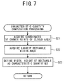
- FIG. 7 is a flowchart of characteristic quantity computation processing that is performed during the first extraction processing
- FIG. 8 is a schematic diagram that shows a form of computing a characteristic quantity for a sewable area R 1 ;
- FIG. 9 is a flowchart of sorting processing that is performed during the first extraction processing
- FIG. 10 is a flowchart of first sewing processing that is performed during the main processing
- FIG. 11 is a flowchart of second extraction processing that is performed during the main processing
- FIG. 12 is a flowchart of second sewing processing that is performed during the main processing
- FIG. 13 is a figure that shows an example of the embroidery patterns that are displayed on the liquid crystal display in a case where only the sewable area R 1 has been defined;
- FIG. 14 is a figure that shows an example of the embroidery patterns that are displayed on the liquid crystal display in a case where a minimum sewing area R 2 has been defined in addition to the sewable area R 1 that is shown in FIG. 13 ;
- FIG. 15 is a flowchart of main processing that is performed by a sewing machine according to a first modified example.
- FIG. 1 A physical configuration of a sewing machine 1 will be explained with reference to FIG. 1 .
- the upper right side of the page corresponds to the right side of the sewing machine 1 .
- the lower left side of the page corresponds to the left side of the sewing machine 1 .
- the upper left side of the page corresponds to the rear side of the sewing machine 1 .
- the lower right side of the page corresponds to the front side (the front face side) of the sewing machine 1 .
- the sewing machine 1 includes a bed 2 , a pillar 3 , and an arm 4 , and a head 5 .
- the bed 2 extends in the left-right direction and supports the sewing machine 1 .
- the pillar 3 is provided such that it rises upward from the right end of the bed 2 .
- the arm 4 extends to the left from the upper end of the pillar 3 , such that it is opposite the bed 2 .
- the head 5 is provided on the left end portion of the arm 4 .
- the head 5 is provided with a needle bar 7 , a presser bar 8 , and the like.
- a sewing machine motor 79 (refer to FIG. 2 ), a drive shaft (not shown in the drawings), and a needle bar up-and-down unit (not shown in the drawings) are provided in the interior of the sewing machine 1 .
- An embroidery frame moving unit 14 is attached to the bed 2 .
- An embroidery frame 12 is attached to the embroidery frame moving unit 14 .
- the embroidery frame 12 holds a work cloth 13 and is moved by the embroidery frame moving unit 14 in an X axis direction (the left-right direction of the sewing machine 1 ) and a Y axis direction (the front-rear direction of the sewing machine 1 ).
- the sewing machine 1 performs sewing of an embroidery pattern by operating the needle bar 7 and the like while the work cloth 13 that is held by the embroidery frame 12 is moved by the embroidery frame moving unit 14 .
- the operations of the embroidery frame moving unit 14 , the needle bar 7 and the like are controlled by a CPU 61 (refer to FIG. 2 ) of the sewing machine 1 , based on embroidery data.
- the pillar 3 is provided with a liquid crystal display 10 on its front face.
- the liquid crystal display 10 is provided with a touch panel 16 on its surface.
- the liquid crystal display 10 is a display that is capable of displaying in color, and it displays an embroidery pattern, an input key, and the like.
- a user inputs one of a desired embroidery pattern and an operating command to the sewing machine 1 by touching a portion of the touch panel 16 that corresponds to the position where the one of the embroidery pattern and the input key is respectively displayed on the liquid crystal display 10 .
- An image that is captured by an image sensor 50 that will be described later is displayed on the liquid crystal display 10 .
- By operating the touch panel 16 using one of a finger and a touch pen (not shown in the drawings), the user can designate an area where the embroidery pattern will be sewn.
- a card slot 17 (refer to FIG. 2 ) into which a memory card 70 (refer to FIG. 2 ) is inserted is provided on the right side face of the pillar 3 .
- the arm 4 in its interior, houses a thread spool (not shown in the drawings) and the like that are used in sewing.
- a front face cover 19 is provided on the front faces of the arm 4 and the head 5 .
- a plurality of operation switches such as a sewing start-and-stop switch 21 , a reverse stitch switch 22 , and the like, are provided on the front face cover 19 .
- the sewing start-and-stop switch 21 is a switch for accepting commands to start and stop the sewing.
- the reverse stitch switch 22 is a switch for using a feed dog (not shown in the drawings) to feed the work cloth 13 from the rear toward the front, which is the opposite of the normal feed direction.
- a speed controller 23 that adjusts the sewing speed (the revolution speed of the drive shaft) is provided on the front face cover 19 .
- the image sensor 50 (refer to FIG. 2 ) is disposed in the interior of the front face cover 19 at a left end lower edge portion 25 .
- the image sensor 50 may be, for example, a known CMOS image sensor.
- the image sensor 50 is mounted such that it faces downward and is capable of capturing an image of an area around a needle drop point through which passes a stitching needle (not shown in the drawings) that is mounted in the needle bar 7 .
- the image sensor 50 may also be one of a CCD camera and another image capture element.
- the sewing machine 1 includes the CPU 61 , a ROM 62 , a RAM 63 , an EEPROM 64 , the card slot 17 , an external access RAM 68 , an input interface 65 , and output interface 66 , and the like. These are all connected to one another through a bus 67 .
- the CPU 61 performs various types of computations and processing in accordance with a control program and performs control of the sewing machine 1 .
- the ROM 62 is a read-only storage element and stores the control program and the like.
- the RAM 63 is a freely readable and writable storage element. The RAM 63 temporarily stores various types of data, such as data for an image that has been captured by the image sensor 50 , a characteristic quantity for an embroidery pattern, which will be described later, and the like.
- the EEPROM 64 is a non-volatile memory. The EEPROM 64 stores various types of data, including image data for messages, operation keys, and the like that are displayed on the liquid crystal display 10 .
- the external access RAM 68 stores various types of data, such as embroidery data and the like, that are read from the memory card 70 that is connected to the card slot 17 .
- the memory card 70 that is connected to the external access RAM 68 is provided with a data table storage area 71 .
- the data table storage area 71 stores a data table that includes various types of data that are related to a plurality of embroidery patterns. The data table will be described later.
- the sewing start-and-stop switch 21 , the reverse stitch switch 22 , the speed controller 23 , the touch panel 16 , the image sensor 50 , and the like are connected to the input interface 65 .
- Drive circuits 73 to 77 are electrically connected to the output interface 66 .
- the drive circuit 73 drives a feed adjustment pulse motor 78 .
- the feed adjustment pulse motor 78 is a motor that adjusts an amount by which the work cloth 13 is fed by the feed dog (not shown in the drawings).
- the drive circuit 74 drives a sewing machine motor 79 .
- the sewing machine motor 79 rotates the drive shaft.
- the drive circuit 75 drives an X axis motor 80 .
- the drive circuit 76 drives a Y axis motor 81 .
- the X axis motor 80 and the Y axis motor 81 are built into the embroidery frame moving unit 14 .
- the X axis motor 80 moves the embroidery frame 12 in the X axis direction (the left-right direction).
- the Y axis motor 81 moves the embroidery frame 12 in the Y axis direction (the front-rear direction).
- the drive circuit 77 drives the liquid crystal display 10 .
- the data table that is stored in the memory card 70 will be explained with reference to FIGS. 3 and 4 .
- the data that are contained in the data table include a control ID, a file name, a width, a height, a thread color list, a classification, image data, and embroidery data.
- the control ID is an ID that is assigned to the embroidery data for an embroidery pattern in order to control the data that are related to the embroidery pattern.
- the file name is a name that is assigned to a data file for the embroidery pattern.
- the width is the width of the smallest rectangle into which the entire embroidery pattern fits, and the height is the height of that smallest rectangle. Therefore, if a rectangular area is larger than the rectangle whose width and height are stored in the data table, the embroidery pattern can be sewn in that area.
- the thread color list is a list of colors of threads that are to be used in the sewing of the embroidery pattern.
- the classification indicates a classification to which the embroidery pattern belongs. In the example that is shown in FIG.
- each of the embroidery patterns belongs to one of the two classifications of “vehicle” and “animal”.
- the image data are data for displaying on the liquid crystal display 10 the embroidery pattern that is to be sewn according to the embroidery data.
- the embroidery data are the data for the sewing of the embroidery pattern by the sewing machine 1 .
- the data for the width and the height are used in a case where an embroidery pattern that will fit into a sewable area is extracted, and in a case where extracted embroidery patterns are sorted in the order in which they will be displayed.
- the data for the thread color list and the classification are used in a case where embroidery patterns are sorted into the order in which they will be displayed, in a case where the embroidery patterns in a designated classification are extracted, and the like.
- FIG. 4 shows a screen that is displayed on the liquid crystal display 10 in a case where the images are displayed for all of the embroidery patterns that are stored in the data table that is shown in FIG. 3 .
- the sewing machine 1 can accordingly display on the liquid crystal display 10 the image data that are stored in the data table.
- the embroidery patterns that are displayed on the liquid crystal display 10 are displayed in color.
- the images of the embroidery patterns with the control IDs 1 to 5 are displayed in the top row, starting on the left.
- the images of the embroidery patterns with the control IDs 6 to 10 are displayed left to right in the second row, those for the control IDs 11 to 15 are displayed in the third row, and those for the control IDs 16 to 20 are displayed in the bottom row.
- the sewing machine 1 displays the widths and the heights along with the images of the embroidery patterns. The user can thereby perceive the sizes of the embroidery patterns, the colors of the threads to be used, and the classifications of the embroidery patterns (vehicle or animal) by looking at the liquid crystal display 10 .
- the sewing machine 1 can also extract the embroidery patterns that will fit into the sewable area and can display only the extracted embroidery patterns on the liquid crystal display 10 . The user can therefore easily and accurately perceive the embroidery patterns that will fit into the sewable area. The user may select a desired embroidery pattern from among the extracted embroidery patterns. The sewing machine 1 can sew the selected embroidery pattern in an appropriate position on the work cloth 13 . This processing will hereinafter be explained in detail.
- the sewing machine 1 acquires gray-scale information for each pixel in the image that has been captured by the image sensor 50 and recognizes the boundary line of the allocated area based on the gray-scale information.
- a method other than the method of drawing an outline on the work cloth 13 can also be used.
- a method may also be used in which a frame member (not shown in the drawings) that is circular, rectangular, or the like is prepared, and the frame member is positioned on the work cloth 13 .
- the user can allocate one allocated area, or two allocated areas on the work cloth 13 .
- the sewing machine 1 treats the allocated area as the sewable area, which is the area where the embroidery pattern can be sewn.
- the user can also allocate a separate area within the one allocated area. In that case, the sewing machine 1 treats the larger area as the sewable area.
- the sewing machine 1 also treats the smaller area within the sewable area as a minimum sewing area.
- the minimum sewing area is an area that specifies the minimum size of the embroidery pattern that will be sewn.
- the user can designate in advance a classification of the embroidery patterns that the user wants to sew. If the user designates a classification, the sewing machine 1 is capable of extracting only the embroidery patterns that belong to the designated classification and notifying the user. After going through the procedures that are described above, (the attaching the work cloth 13 , the allocating of the allocated area, and, if necessary, the designating of the classification), the user starts the main processing.
- Step S 1 when the main processing is started, an image of the work cloth 13 is captured by the image sensor 50 (Step S 1 ). Known image processing is performed on the captured image, and the gray-scale information is acquired for each pixel (Step S 2 ). The acquired gray-scale information is binarized (Step S 3 ). The allocated area that the user has allocated on the work cloth 13 is recognized by detecting the outline of the allocated area based on the binarized gray-scale information (Step S 4 ).
- the first extraction processing is processing that extracts an embroidery pattern in a case where one allocated area has been allocated on the work cloth 13 .
- the one recognized allocated area is defined as a sewable area R 1 (Step S 11 ).
- Characteristic quantities for the defined sewable area R 1 are computed by characteristic quantity computation processing (Step S 12 ).
- the characteristic quantities are quantities that specify at least the size of the sewable area R 1 .
- two quantities, the width and the height are used as the characteristic quantities.
- the width and the height of the largest rectangle that will fit into the sewable area R 1 are computed as the characteristic quantities for the defined sewable area R 1 .
- the coordinates of corner points (points 85 , 86 , 87 , 88 , 89 in FIG. 8 ) on the boundary line of the sewable area R 1 , which is a closed area, are acquired (Step S 21 ). This makes it possible to identify the coordinates of the points within the sewable area R 1 .
- the maximum rectangle for which the four points that serve as the corners are points within the sewable area R 1 is acquired (Step S 22 ).
- the width and the height of the acquired rectangle 90 are defined as the characteristic quantities for the sewable area R 1 (Step S 23 ).
- characteristic quantities A for each of the embroidery patterns that are stored in the data table are compared to corresponding characteristic quantities B that have been computed for the sewable area R 1 (Step S 13 ).
- the embroidery patterns for which the characteristic quantities A are not greater than the corresponding characteristic quantities B for the sewable area R 1 are extracted from the embroidery patterns in the data table (Step S 14 ).
- the embroidery patterns for which both the width and the height fit within the sewable area R 1 are extracted. More specifically, the embroidery patterns for which the width is not greater than the computed width of the sewable area R 1 and the height is not greater than the computed height of the sewable area R 1 are extracted.
- Step S 41 a determination is made as to whether one of the embroidery patterns that are displayed on the liquid crystal display 10 has been selected by the user (Step S 41 ). This determination is repeatedly made (NO at Step S 41 ) until one of the embroidery patterns has been selected.
- the selected embroidery pattern is set as the embroidery pattern that will actually be sewn on the work cloth 13 (Step S 42 ).
- the embroidery pattern that has been set and the sewable area R 1 are displayed on the liquid crystal display 10 such that their centers are aligned (Step S 43 ).
- Arrow keys (not shown in the drawings) are also displayed in a portion of the liquid crystal display 10 .
- Step S 46 IF the sewing start-and-stop switch 21 has not been operated (NO at Step S 46 ), the processing returns to the determination at Step S 44 . If the sewing start-and-stop switch 21 has been operated (YES at Step S 46 ), the embroidery pattern that the user has selected is sewn, in accordance with the embroidery data, within the sewable area R 1 on the work cloth 13 for which the image has been captured, in the position that has been adjusted using the arrow keys (Step S 47 ). The processing returns to the main processing, which is then terminated.
- the second extraction processing and the second sewing processing will be explained with reference to FIGS. 11 and 12 .
- the second extraction processing that is shown in FIG. 11 is processing that extracts the embroidery patterns in a case where two allocated areas have been allocated on the work cloth 13 .
- the larger of the two allocated areas that have been recognized is defined as the sewable area R 1 (Step S 51 ).
- the smaller area that has been recognized within the larger allocated area is defined as a minimum sewing area R 2 for specifying the minimum size of the embroidery pattern that will be sewn (Step S 52 ).
- the characteristic quantity computation processing is performed for each of the two defined areas R 1 and R 2 (Step S 53 ).
- the processing is the same as the processing that is shown in FIG. 7 .
- the characteristic quantity computation processing the width and the height of the largest rectangle that fits within the area are computed as the characteristic quantities.
- the characteristic quantities A for each of the embroidery patterns that are stored in the data table are compared to the corresponding characteristic quantities B for the sewable area R 1 and to characteristic quantities C for the minimum sewing area R 2 (Step S 54 ).
- the embroidery patterns for which the characteristic quantities A are not greater than the corresponding characteristic quantities B for the sewable area R 1 and not less than the corresponding characteristic quantities C for the minimum sewing area R 2 are extracted from the embroidery patterns in the data table (Step S 55 ). In other words, the embroidery patterns for which both the width and the height fit within the sewable area R 1 and the width and the height are not less than the width and the height of the minimum sewing area R 2 are extracted.
- Step S 56 A determination is made as to whether a classification has been designated for the embroidery pattern (Step S 56 ). If a classification has not been designated (NO at Step S 56 ), the processing proceeds to Step S 58 . If the classification has been designated (YES at Step S 56 ), the embroidery patterns that belong to the designated classification are extracted from the embroidery patterns that have already been extracted (Step S 57 ). Next, the sorting processing is performed that sorts the extracted embroidery patterns into a specified order (Step S 58 ). The sorting processing is the same as the processing that is shown in FIG. 9 , so an explanation will be omitted. The extracted embroidery patterns are displayed in an array on the liquid crystal display 10 in the order in which they have been sorted by the sorting processing (Step S 59 ). The processing then returns to the main processing (refer to FIG. 5 ), and the second sewing processing is performed (Step S 9 ).
- Step S 61 a determination is made as to whether one of the embroidery patterns that are displayed on the liquid crystal display 10 has been selected by the user (Step S 61 ).
- the determination at Step S 61 is repeatedly made (NO at Step S 61 ) until one of the embroidery patterns has been selected.
- the selected embroidery pattern is set as the embroidery pattern that will be sewn on the work cloth 13 (Step S 62 ).
- the embroidery pattern that has been set is displayed on the liquid crystal display 10 such that it fits within the sewable area R 1 and is superimposed on the minimum sewing area R 2 (Step S 63 ).
- Step S 66 If the sewing start-and-stop switch 21 has not been operated (NO at Step S 66 ), the processing returns to the determination at Step S 64 . If the sewing start-and-stop switch 21 has been operated (YES at Step S 66 ), the embroidery pattern that the user has selected is sewn in the position that has been set within the sewable area R 1 (Step S 67 ). The processing returns to the main processing, which is then terminated.
- Step S 6 the recognized allocated area is defined as the sewable area R 1 (Step S 11 ), and the characteristic quantities for the defined sewable area R 1 are computed (Step S 12 ).
- the computed characteristic quantities are a width of 6.2 centimeters and a height of 6.0 centimeters.
- the embroidery patterns for which the width is not greater than 6.2 centimeters and the height is not greater than 6.0 centimeters are extracted from the embroidery patterns in the data table (refer to FIG. 3 ) (Step S 14 ).
- the extracted embroidery patterns are sorted in descending order by their surface areas (Step S 17 ) and are displayed in an array on the liquid crystal display 10 (Step S 18 ).
- the results that are displayed in this case are shown in FIG. 13 .
- the embroidery patterns that are shown in FIG. 13 can be sewn within the sewable area R 1 without being reduced, having their shapes changed, or the like.
- the two allocated areas are recognized (YES at Step S 5 ), and the second extraction processing is performed (Step S 8 ).
- the larger of the two recognized allocated areas is defined as the sewable area R 1 (Step S 51 ).
- the smaller area within the sewable area R 1 is defined as the minimum sewing area R 2 (Step S 52 ).
- the characteristic quantities are computed for the two areas R 1 and R 2 (Step S 53 ).
- the computed characteristic quantities for the sewable area R 1 are a width of 6.2 centimeters and a height of 6.0 centimeters, the same as in the previously described example.
- the computed characteristic quantities for the minimum sewing area R 2 are a width of 0.8 centimeters and a height of 2.0 centimeters.
- the embroidery patterns for which the width is not less than 0.8 centimeters and not greater than 6.2 centimeters and the height is not less than 2.0 centimeters and not greater than 6.0 centimeters are extracted (Step S 55 ).
- the embroidery patterns that belong to the classification “animal” are extracted from the previously extracted embroidery patterns (Step S 57 ).
- the extracted embroidery patterns are sorted in descending order by their surface areas (Step S 58 ) and are displayed on the liquid crystal display 10 (Step S 59 ).
- the results that are displayed in this case are shown in FIG. 14 .
- the embroidery patterns that are smaller than the minimum sewing area R 2 are not extracted by the second extraction processing. This makes it possible for the user to recognize easily and accurately which of the embroidery patterns fits within the sewable area R 1 and has the desired size. By designating the desired classification, the user can cause only the embroidery patterns that belong to the designated classification to be displayed.
- the sewing machine 1 defines the sewable area R 1 , which is the area within which the embroidery pattern can be sewn.
- the sewing machine 1 can extract the embroidery patterns that fit into the sewable area R 1 and notify the user. The user can therefore easily and accurately recognize what embroidery patterns can be sewn in the sewable area R 1 without being processed. If the user allocates two allocated areas, the sewing machine 1 defines the smaller of the allocated areas as the minimum sewing area R 2 . The sewing machine 1 does not extract the embroidery patterns for which the characteristic quantities are smaller than those for the minimum sewing area R 2 . The user can therefore easily cause the sewing machine 1 to extract the embroidery patterns of the desired size.
- the user can also adjust the position of the embroidery pattern within the sewable area R 1 and within the range in which the embroidery pattern is superimposed on the minimum sewing area R 2 .
- fine adjustment of the position of the embroidery pattern can be performed easily by using the position of the minimum sewing area R 2 as a reference.
- the sewing machine 1 can sort the extracted embroidery patterns in a specified order and display them on the liquid crystal display 10 . This makes it possible for the user to recognize the extracted embroidery patterns accurately in accordance with the specified order.
- the sewing machine 1 computes, as the characteristic quantities for the sewable area R 1 , the width and the height of the largest rectangle that fits within the sewable area R 1 . This makes it possible to easily extract the embroidery patterns that fit within the sewable area R 1 , regardless of the shape of the sewable area R 1 .
- the sewing machine 1 Based on the image data of the work cloth 13 that have been captured by the image sensor 50 , the sewing machine 1 recognizes the allocated areas that have been allocated on the work cloth 13 .
- the sewing machine 1 can define the recognized allocated areas as the sewable area R 1 and the minimum sewing area R 2 . This makes it possible for the user to cause the sewing machine 1 to define the sewable area R 1 and the minimum sewing area R 2 of the desired sizes and in the desired positions on the work cloth 13 , by allocating the allocated areas on the work cloth 13 and causing the image sensor 50 to capture an image of the work cloth 13 .
- the sewing machine 1 can accurately sew the embroidery pattern that the user has selected in an appropriate position within the sewable area R 1 on the work cloth 13 for which the image sensor 50 has captured the image.
- a first modified example of the embodiment that is described above will be explained with reference to FIG. 15 .
- the sewing machine 1 according to the first modified example differs from the sewing machine 1 according to the embodiment that is described above only in the method for defining the sewable area R 1 and the minimum sewing area R 2 . Accordingly, explanations will be one of omitted and simplified for any processing that is the same as the pressing in the embodiment that is described above.
- the user allocates the allocated areas on the work cloth 13 in advance and then starts the main processing.
- the user can operate the touch panel 16 in order to define the sewable area R 1 and the minimum sewing area R 2 on the work cloth 13 that is displayed on the liquid crystal display 10 .
- the user uses the embroidery frame 12 to secure the work cloth 13 in the sewing machine 1 , then starts the main processing.
- Step S 71 when the main processing is started, an image of the work cloth 13 is captured by the image sensor 50 (Step S 71 ). An area defining screen is displayed on the liquid crystal display 10 (Step S 72 ). The captured image of the work cloth 13 is displayed on the area defining screen. Next, an area defining operation by the user is accepted (Step S 73 ). The user defines a closed area by using a finger, a touch pen (not shown in the drawings), or the like to trace the desired position on the work cloth 13 that is being displayed on the liquid crystal display 10 . If the defining of the areas by the user has not been completed (NO at Step S 74 ), the processing returns to Step S 72 , and the defined areas are displayed on the liquid crystal display 10 .
- Step S 75 a determination is made as to whether two areas have been defined. If only one area has been defined (NO at Step S 75 ), the one area that the user has defined is defined as the sewable area R 1 , and the subsequent processing is performed (Steps S 6 , S 7 ). If two areas have been defined (YES at Step S 75 ), the larger area is defined as the sewable area R 1 , the smaller area is defined as the minimum sewing area R 2 , and the subsequent processing is performed (Steps S 8 , S 9 ).
- the user is able to define the sewable area R 1 and the minimum sewing area R 2 of the appropriate sizes and in the appropriate positions on the work cloth 13 while watching the work cloth 13 that is displayed on the liquid crystal display 10 . There is no need for the user to perform a task such as redrawing the areas on the work cloth 13 or the like.
- the sewing machine 1 recognizes at least one color of the portion of the work cloth 13 that is within the sewable area R 1 .
- the sewing machine 1 sorts the embroidery patterns that fit into the sewable area R 1 in descending order according to the number of threads that the embroidery patterns use that are similar in color to the at least one color of the work cloth 13 that the sewing machine 1 has recognized.
- the sorting processing according to the second modified example (refer to FIG. 9 ) performs processing that recognizes the at least one color of the portion of the work cloth 13 that is within the sewable area R 1 , instead of the processing that computes the surface area (Step S 32 ).
- the sewing machine 1 refers to the thread color lists that have been acquired from the data table (refer to FIG. 3 ) and sorts the embroidery patterns in descending order according to the number of threads that are used that are similar in color to the at least one color of the work cloth 13 that has been recognized.
- the order in which the extracted embroidery patterns are sorted is not limited to being the descending order according to the surface area of the embroidery pattern.
- a method that sorts the embroidery patterns numerically according to the control ID or the like can also be used.
- the processing that extracts the embroidery patterns that fit within the sewable area R 1 and notifies the user is performed by the sewing machine 1 .
- the processing may also be performed by another device, such as a personal computer or the like.
- the program for performing the main processing is stored in the ROM 62 .
- the program may also be stored in another storage medium, such as the EEPROM 64 , a CD-ROM that is not shown in the drawings, or the like.
- the sewing machine 1 performs the extracting of the embroidery patterns using the widths and the heights of the areas as the characteristic quantities.
- any quantity that at least makes it possible to specify the size of an area can be used as the characteristic quantity.
- the sewing machine 1 may also extract the embroidery patterns by identifying the largest ellipse that fits within the sewable area R 1 , then comparing the major axis and the minor axis of the ellipse to the major axis and the minor axis of an ellipse that surrounds the entire embroidery pattern.
- the sewing machine 1 may also use another parameter, such as a degree of circularity or the like, as a characteristic quantity.
- the method for computing the characteristic quantities for the minimum sewing area R 2 is the same as the method for computing the characteristic quantities for the sewable area R 1 . That is, the width and the height of the largest rectangle that fits within the minimum sewing area R 2 are computed as the characteristic quantities.
- the method for computing the characteristic quantities for the minimum sewing area R 2 can be modified.
- the sewing machine 1 may also compute the width and the height of the smallest rectangle within which the minimum sewing area R 2 fits as the characteristic quantities. In that case, only the embroidery patterns of a size that can cover the entire minimum sewing area R 2 will be extracted.
Landscapes
- Engineering & Computer Science (AREA)
- Textile Engineering (AREA)
- Computer Hardware Design (AREA)
- Microelectronics & Electronic Packaging (AREA)
- Sewing Machines And Sewing (AREA)
Abstract
Description
Claims (20)
Applications Claiming Priority (2)
| Application Number | Priority Date | Filing Date | Title |
|---|---|---|---|
| JP2009-240060 | 2009-10-19 | ||
| JP2009240060A JP2011083510A (en) | 2009-10-19 | 2009-10-19 | Embroidery data processing device, sewing machine, embroidery data processing program, and storage medium storing embroidery data processing program |
Publications (2)
| Publication Number | Publication Date |
|---|---|
| US20110088604A1 US20110088604A1 (en) | 2011-04-21 |
| US8820252B2 true US8820252B2 (en) | 2014-09-02 |
Family
ID=43878297
Family Applications (1)
| Application Number | Title | Priority Date | Filing Date |
|---|---|---|---|
| US12/902,809 Active 2033-07-03 US8820252B2 (en) | 2009-10-19 | 2010-10-12 | Embroidery data processing device, computer-readable storage medium storing embroidery data processing program, and sewing machine |
Country Status (2)
| Country | Link |
|---|---|
| US (1) | US8820252B2 (en) |
| JP (1) | JP2011083510A (en) |
Families Citing this family (1)
| Publication number | Priority date | Publication date | Assignee | Title |
|---|---|---|---|---|
| JP7694112B2 (en) * | 2021-03-31 | 2025-06-18 | ブラザー工業株式会社 | Sewing System |
Citations (9)
| Publication number | Priority date | Publication date | Assignee | Title |
|---|---|---|---|---|
| US4823714A (en) * | 1987-04-24 | 1989-04-25 | Brother Kogyo Kabushiki Kaisha | Electronic controlled stitch pattern sewing machine and method |
| US5228403A (en) * | 1991-11-06 | 1993-07-20 | Brother Kogyo Kabushiki Kaisha | Sewing machine for sewing continuous pattern consisting of plurality of partial patterns |
| JPH0538705Y2 (en) | 1987-07-17 | 1993-09-30 | ||
| US5255620A (en) * | 1989-12-22 | 1993-10-26 | Janome Sewing Machine Co., Ltd. | Apparatus for adjusting the size of a sewing machine pattern |
| JPH06233883A (en) | 1993-02-10 | 1994-08-23 | Brother Ind Ltd | Embroidery data forming device for embroidering machine |
| JPH09176952A (en) | 1995-12-22 | 1997-07-08 | Brother Ind Ltd | Embroidery data processing device and embroidery data processing method |
| US5671410A (en) * | 1994-06-08 | 1997-09-23 | Brother Kogyo Kabushiki Kaisha | Data storing device having a capacity determining system |
| US5855176A (en) * | 1997-05-07 | 1999-01-05 | Janome Sewing Machine Co., Ltd. | Embroidery stitch data producing device and sewing machine |
| US6600966B1 (en) * | 2002-02-26 | 2003-07-29 | Brian D. Bailie | Software program, method and system for dividing an embroidery machine design into multiple regional designs |
-
2009
- 2009-10-19 JP JP2009240060A patent/JP2011083510A/en active Pending
-
2010
- 2010-10-12 US US12/902,809 patent/US8820252B2/en active Active
Patent Citations (10)
| Publication number | Priority date | Publication date | Assignee | Title |
|---|---|---|---|---|
| US4823714A (en) * | 1987-04-24 | 1989-04-25 | Brother Kogyo Kabushiki Kaisha | Electronic controlled stitch pattern sewing machine and method |
| JPH0538705Y2 (en) | 1987-07-17 | 1993-09-30 | ||
| US5255620A (en) * | 1989-12-22 | 1993-10-26 | Janome Sewing Machine Co., Ltd. | Apparatus for adjusting the size of a sewing machine pattern |
| US5228403A (en) * | 1991-11-06 | 1993-07-20 | Brother Kogyo Kabushiki Kaisha | Sewing machine for sewing continuous pattern consisting of plurality of partial patterns |
| JPH06233883A (en) | 1993-02-10 | 1994-08-23 | Brother Ind Ltd | Embroidery data forming device for embroidering machine |
| US5390615A (en) | 1993-02-10 | 1995-02-21 | Brother Kogyo Kabushiki Kaisha | Embroidery machine |
| US5671410A (en) * | 1994-06-08 | 1997-09-23 | Brother Kogyo Kabushiki Kaisha | Data storing device having a capacity determining system |
| JPH09176952A (en) | 1995-12-22 | 1997-07-08 | Brother Ind Ltd | Embroidery data processing device and embroidery data processing method |
| US5855176A (en) * | 1997-05-07 | 1999-01-05 | Janome Sewing Machine Co., Ltd. | Embroidery stitch data producing device and sewing machine |
| US6600966B1 (en) * | 2002-02-26 | 2003-07-29 | Brian D. Bailie | Software program, method and system for dividing an embroidery machine design into multiple regional designs |
Also Published As
| Publication number | Publication date |
|---|---|
| JP2011083510A (en) | 2011-04-28 |
| US20110088604A1 (en) | 2011-04-21 |
Similar Documents
| Publication | Publication Date | Title |
|---|---|---|
| US8061286B2 (en) | Sewing machine and computer-readable medium storing sewing machine control program | |
| US8607721B2 (en) | Sewing machine and computer readable medium | |
| US9249533B2 (en) | Sewing machine | |
| US9885131B2 (en) | Sewing machine | |
| US8948901B2 (en) | Sewing machine | |
| US10597806B2 (en) | Sewing machine and non-transitory computer-readable storage medium | |
| US10626532B2 (en) | Non-transitory computer-readable medium storing sewing data generation program, sewing data generation device and sewing method | |
| EP2233627A2 (en) | Sewing machine and computer-readable medium storing control program executable on sewing machine | |
| EP2423364A1 (en) | Sewing machine and non-transitory computer-readable medium storing sewing machine control program | |
| US8914144B2 (en) | Sewing machine, apparatus, and non-transitory computer-readable medium | |
| US8733260B2 (en) | Embroidery data processing apparatus and computer-readable medium storing embroidery data processing program | |
| US6502006B1 (en) | Method and system for computer aided embroidery | |
| US8061287B2 (en) | Sewing data processing apparatus, sewing machine equipped with sewing data processing apparatus, and computer-readable recording medium with recorded sewing data processing computer program | |
| US8820252B2 (en) | Embroidery data processing device, computer-readable storage medium storing embroidery data processing program, and sewing machine | |
| US10662564B2 (en) | Sewing machine and non-transitory computer-readable medium | |
| US9194068B2 (en) | Sewing machine and non-transitory computer-readable medium storing sewing machine control program | |
| JP2015104442A (en) | sewing machine | |
| US20130213285A1 (en) | Sewing data generating device and non-transitory computer-readable storage medium storing sewing data generating program | |
| US9290873B2 (en) | Sewing machine, information processing apparatus, and non-transitory computer-readable medium | |
| US20010012013A1 (en) | Display device for sewing machine | |
| US10344411B2 (en) | Sewing machine and non-transitory computer-readable medium | |
| CN208533093U (en) | A kind of pattern sewing machine of automatic realization sewing end point setting | |
| US8033232B2 (en) | Embroidery data processing apparatus, sewing machine equipped with the embroidery data processing apparatus, and computer-readable recording medium with recorded embroidery data processing computer program | |
| US11473228B2 (en) | Non-transitory computer-readable medium and embroidery data generation method | |
| US20130138240A1 (en) | Display control apparatus, sewing machine, and non-transitory computer-readable medium storing sewing machine control program |
Legal Events
| Date | Code | Title | Description |
|---|---|---|---|
| AS | Assignment |
Owner name: BROTHER KOGYO KABUSHIKI KAISHA, JAPAN Free format text: ASSIGNMENT OF ASSIGNORS INTEREST;ASSIGNORS:TAKAHATA, HIROTSUGU;KATO, HARUMI;TASHIRO, NORIHARU;AND OTHERS;REEL/FRAME:025135/0317 Effective date: 20101001 |
|
| STCF | Information on status: patent grant |
Free format text: PATENTED CASE |
|
| MAFP | Maintenance fee payment |
Free format text: PAYMENT OF MAINTENANCE FEE, 4TH YEAR, LARGE ENTITY (ORIGINAL EVENT CODE: M1551) Year of fee payment: 4 |
|
| MAFP | Maintenance fee payment |
Free format text: PAYMENT OF MAINTENANCE FEE, 8TH YEAR, LARGE ENTITY (ORIGINAL EVENT CODE: M1552); ENTITY STATUS OF PATENT OWNER: LARGE ENTITY Year of fee payment: 8 |
|
| MAFP | Maintenance fee payment |
Free format text: PAYMENT OF MAINTENANCE FEE, 12TH YEAR, LARGE ENTITY (ORIGINAL EVENT CODE: M1553); ENTITY STATUS OF PATENT OWNER: LARGE ENTITY Year of fee payment: 12 |