US8814163B2 - Paper feeder - Google Patents
Paper feeder Download PDFInfo
- Publication number
- US8814163B2 US8814163B2 US13/432,114 US201213432114A US8814163B2 US 8814163 B2 US8814163 B2 US 8814163B2 US 201213432114 A US201213432114 A US 201213432114A US 8814163 B2 US8814163 B2 US 8814163B2
- Authority
- US
- United States
- Prior art keywords
- sheet
- paper feed
- conveying speed
- conveying
- feed roller
- Prior art date
- Legal status (The legal status is an assumption and is not a legal conclusion. Google has not performed a legal analysis and makes no representation as to the accuracy of the status listed.)
- Active
Links
Images


Classifications
-
- B—PERFORMING OPERATIONS; TRANSPORTING
- B65—CONVEYING; PACKING; STORING; HANDLING THIN OR FILAMENTARY MATERIAL
- B65H—HANDLING THIN OR FILAMENTARY MATERIAL, e.g. SHEETS, WEBS, CABLES
- B65H5/00—Feeding articles separated from piles; Feeding articles to machines
- B65H5/34—Varying the phase of feed relative to the receiving machine
-
- B—PERFORMING OPERATIONS; TRANSPORTING
- B65—CONVEYING; PACKING; STORING; HANDLING THIN OR FILAMENTARY MATERIAL
- B65H—HANDLING THIN OR FILAMENTARY MATERIAL, e.g. SHEETS, WEBS, CABLES
- B65H9/00—Registering, e.g. orientating, articles; Devices therefor
- B65H9/004—Deskewing sheet by abutting against a stop, i.e. producing a buckling of the sheet
- B65H9/006—Deskewing sheet by abutting against a stop, i.e. producing a buckling of the sheet the stop being formed by forwarding means in stand-by
-
- B—PERFORMING OPERATIONS; TRANSPORTING
- B65—CONVEYING; PACKING; STORING; HANDLING THIN OR FILAMENTARY MATERIAL
- B65H—HANDLING THIN OR FILAMENTARY MATERIAL, e.g. SHEETS, WEBS, CABLES
- B65H9/00—Registering, e.g. orientating, articles; Devices therefor
- B65H9/14—Retarding or controlling the forward movement of articles as they approach stops
-
- B—PERFORMING OPERATIONS; TRANSPORTING
- B65—CONVEYING; PACKING; STORING; HANDLING THIN OR FILAMENTARY MATERIAL
- B65H—HANDLING THIN OR FILAMENTARY MATERIAL, e.g. SHEETS, WEBS, CABLES
- B65H2513/00—Dynamic entities; Timing aspects
- B65H2513/10—Speed
-
- B—PERFORMING OPERATIONS; TRANSPORTING
- B65—CONVEYING; PACKING; STORING; HANDLING THIN OR FILAMENTARY MATERIAL
- B65H—HANDLING THIN OR FILAMENTARY MATERIAL, e.g. SHEETS, WEBS, CABLES
- B65H2557/00—Means for control not provided for in groups B65H2551/00 - B65H2555/00
- B65H2557/20—Calculating means; Controlling methods
- B65H2557/24—Calculating methods; Mathematic models
- B65H2557/242—Calculating methods; Mathematic models involving a particular data profile or curve
-
- B—PERFORMING OPERATIONS; TRANSPORTING
- B65—CONVEYING; PACKING; STORING; HANDLING THIN OR FILAMENTARY MATERIAL
- B65H—HANDLING THIN OR FILAMENTARY MATERIAL, e.g. SHEETS, WEBS, CABLES
- B65H2801/00—Application field
- B65H2801/03—Image reproduction devices
- B65H2801/06—Office-type machines, e.g. photocopiers
Definitions
- the present invention relates to a paper feeder provided to an image forming apparatus.
- paper feeders which are provided to an image forming apparatus and configured to convey a sheet of paper (hereinafter referred to as sheet) taken out from a paper feed tray to an image formation unit by using resist rollers, the image formation unit including ink jet heads or the like.
- a sheet hits the resist rollers and is held against the resist rollers temporarily. In this way, a warpage is formed on the sheet. This corrects oblique conveyance of the sheet.
- the paper feeder then drives the resist rollers at a predetermined time to send the sheet to the image formation unit.
- the sheet causes a collision noise when hitting the resist rollers.
- the collision noise is loud especially in an image forming apparatus capable of a high throughput (the number of sheets printed per unit time) because sheets are conveyed at a high speed therein. Moreover, the damage on the sheet due to the collision is large as well.
- Japanese Unexamined Patent Application Publication No. 2009-40568 discloses a paper feeder in which: paper feed rollers convey a sheet at a first conveying speed; and the conveying speed of the paper feed rollers is decelerated to a second conveying speed, which is lower than the first conveying speed, when a detector provided between the paper feed rollers and resist rollers detects the leading end of the sheet.
- the second conveying speed is set based on the time point at which the detector detects the leading end of the sheet.
- the second conveying speed is set based on the time point at which the detector detects the leading end of the sheet, the second conveying speed can be still too high in some cases, depending upon the time at which the leading end of the sheet reaches the detector. This leads to a loud collision noise of the sheet with the resist rollers, failing to provide an enough noise reduction effect.
- the present invention has an object to provide a paper feeder capable of reducing a noise while maintaining its throughput.
- An aspect of the present invention is a paper feeder comprising: a resist roller configured to convey a sheet to an image formation unit; a paper feed roller configured to convey a sheet to the resist roller; and a controller configured to control the paper feed roller such that the paper feed roller first conveys a sheet at a first conveying speed and then conveys the sheet while decelerating from the first conveying speed to a second conveying speed slower than the first conveying speed, the controller being configured to set the first and second conveying speeds in advance to speeds which allow the paper feed roller to convey a single sheet by a predetermined conveying amount in a predetermined driving time period, the controller being configured to determine a time point to start a deceleration from the first conveying speed to the second conveying speed to allow a sheet to hit the resist roller at the second conveying speed.
- the controller sets the first and second conveying speeds in advance which allow the paper feed roller to convey a single sheet by a predetermined conveying amount in a predetermined driving time period. Then, the controller controls the paper feed roller in such a way that it first conveys the sheet at the first conveying speed and then conveys the sheet while decelerating from the first conveying speed to the slower second conveying speed. In this event, the controller determines the time point to start the deceleration from the first conveying speed to the second conveying speed such that the sheet can hit the resist roller at the second conveying speed. In this way, the paper feeder can make the sheet hit the resist roller at the previously set, second conveying speed to reduce the noise while maintaining the throughput.
- the paper feeder may further comprise a detection unit disposed between the paper feed roller and the resist roller and configured to detect a sheet.
- the controller may determine the time point to start the deceleration on a basis of a time point at which the detection unit detects a leading end of a sheet conveyed at the first conveying speed.
- the time point to start the deceleration from the first conveying speed to the second conveying speed is determined based on the time point at which the detection unit detects the leading end of the sheet. In this way, the paper feeder can hit the sheet against the resist roller at the second conveying speed to reduce the noise even if there are variations in the time at which the sheet reaches the detection unit.
- the paper feeder may further comprise a conveying-amount acquisition unit configured to acquire information indicative of a conveying amount of a sheet conveyed by the paper feed roller.
- a conveying-amount acquisition unit configured to acquire information indicative of a conveying amount of a sheet conveyed by the paper feed roller.
- the controller when the conveying amount of the paper feed roller indicated by the information acquired by the conveying-amount acquisition unit reaches a predetermined value, the controller starts the deceleration of the conveying speed of the paper feed roller from the second conveying speed. In this way, the paper feeder can accurately stop the paper feed roller in accordance with the actual conveying amount.
- FIG. 1 is a schematic configuration diagram of an image forming apparatus including a paper feeder of an embodiment of the present invention.
- FIG. 2 is a block diagram showing the configuration of a control system of the image forming apparatus shown in FIG. 1 .
- FIG. 3 is a timing chart showing changes in the detection signal of a paper sensor and in the conveying speeds of paper feed rollers and resist rollers.
- FIG. 4 is an enlarged diagram of a chief portion of the image forming apparatus shown in FIG. 1 .
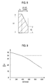
- FIG. 5 is a diagram for describing a warping amount.
- FIG. 6 is a diagram for describing a method of determining a conveying speed V 1 .
- FIG. 7 is a diagram for describing a method of determining a conveying speed V 2 .
- FIG. 8 is a diagram for describing the method of determining the conveying speed V 2 .
- FIG. 9 is a diagram for describing the method of determining the conveying speed V 1 .
- FIG. 10 is a flowchart for describing control on the paper feed controllers.
- FIG. 11 is a diagram showing example measurement data of the conveying speed of the paper feed rollers in the image forming apparatus of the embodiment.
- FIG. 12 is a diagram showing example measurement data of the conveying speed of the paper feed rollers that is based on a related drive control.
- FIG. 1 is a schematic configuration diagram of an imaging forming apparatus including a paper feeder 10 of the embodiment of the present invention.
- FIG. 2 is a block diagram showing the configuration of a control system of the image forming apparatus shown in FIG. 1 .
- Top, bottom, left, and right in the following description refer to top, bottom, left, and right shown in FIG. 1 , respectively.
- the path shown by the broken line in FIG. 1 is a conveying path R through which sheets are conveyed, and a direction from left to right is the conveying direction.
- Upstream and downstream in the following description refer to upstream and downstream in the conveying path R, respectively.
- an image forming apparatus 1 includes a paper feed unit 2 , an image formation unit 3 , and a controller 4 .
- the paper feeder 10 includes the paper feed unit 2 and the controller 4 .
- the paper feed unit 2 is configured to supply (feed) sheets to the image formation unit 3 .
- the paper feed unit 2 is provided at the most upstream side of the conveying path R.
- the paper feed unit 2 includes a paper feed tray 21 , paper feed rollers 22 , a paper feed motor 23 , a stripper plate 24 , resist rollers 25 , a resist motor 26 , an encoder 27 , and a paper sensor 28 .
- the paper feed tray 21 is where sheets P being image formation media are loaded.
- the paper feed rollers 22 are configured to individually take out the sheets P loaded on the paper feed tray 21 and to convey it to the resist rollers 25 .
- the paper feed rollers 22 are disposed above the paper feed tray 21 .
- the paper feed rollers 22 have such a structure that they rotate by using the drive force of the paper feed motor 23 but, when the resist rollers 25 start to convey the sheet P, are rotated by movement of the sheet P.
- the paper feed motor 23 is configured to rotationally drive the paper feed rollers 22 .
- the stripper plate 24 is configured to strip a sheet off other sheets so that the paper feed rollers 22 can convey the sheets one by one.
- the stripper plate 24 is in pressure contact with the downstream paper feed roller 22 from below.
- the resist rollers 25 are configured to convey the sheet P, sent from the paper feed rollers 22 , to the image formation unit 3 at a predetermined timing after the sheet P hits the resist rollers 25 .
- the resist rollers 25 are disposed downstream of the paper feed rollers 22 .
- the resist motor 26 is configured to rotationally drive the resist rollers 25 .
- the encoder 27 is configured to detect the rotation angle of the rotary shaft of the paper feed motor 23 and generate a pulse signal corresponding to the rotation angle. This pulse signal is equivalent to information indicative of the conveying amount of the sheet P which the paper feed rollers 22 are conveying.
- the encoder 27 is equivalent to a conveying-amount acquisition unit.
- the paper sensor 28 is disposed between the paper feed rollers 22 and the resist rollers 25 and is configured to detect the sheet P that is being conveyed on the conveying path R.
- the paper sensor 28 is formed of an optical sensor having a light emitting element and a light receiving element, for example.
- the paper sensor 28 is equivalent to a detection unit.
- the image formation unit 3 is configured to form an image on the sheet P while conveying the sheet P.
- the image formation unit 3 includes a belt conveyer unit 31 , a belt motor 32 , and an ink jet head unit 33 .
- the belt conveyer unit 31 is configured to hold, on a looped conveyer belt, the sheet P fed from the paper feed unit 2 and to convey the sheet P by rotationally driving the conveyer belt.
- the belt conveyer unit 31 is disposed downstream of the resist rollers 25 .
- the belt motor 32 is configured to rotationally drive the conveyer belt that holds and conveys the sheet P in the belt conveyer unit 31 .
- the ink jet head unit 33 is disposed above the belt conveyer unit 31 and has multiple line-type ink jet heads each having multiple nozzles aligned in a direction perpendicular to the conveying direction of the sheet P.
- the ink jet head unit 33 is configured to jet inks from the ink jet heads to form an image on the sheet P conveyed by the belt conveyer unit 31 .
- the controller 4 is configured to control the operation of each unit in the image forming apparatus 1 .
- the controller 4 is formed of a CPU, a RAM, a ROM, and the like.
- the controller 4 performs control that causes the paper feed unit 2 to feed the sheet P to the image formation unit 3 , causes the belt conveyer unit 31 to convey the sheet P, and causes the ink jet head unit 33 to jet inks to print an image on the sheet P.
- the controller 4 drives the paper feed rollers 22 and the resist rollers 25 alternately for each individual sheet to be fed.
- the controller 4 controls the paper feed rollers 22 in such a way that they first convey the sheet P at a conveying speed V 1 (first conveying speed) and then convey the sheet P while decelerating from the conveying speed V 1 to a slower conveying speed V 2 (second conveying speed).
- the controller 4 determines the time point to start the deceleration from the conveying speed V 1 to the conveying speed V 2 such that the sheet can hit the resist rollers 25 at the conveying speed V 2 .
- the controller 4 sets up the conveying speeds V 1 and V 2 in advance as speeds with which the paper feed rollers 22 can convey a single sheet by a predetermined conveying amount La in a predetermined driving time period Ta.
- the driving time period Ta is determined as a time period allowed to drive the paper feed rollers 22 to achieve a desired throughput (the number of sheets printed per unit time) of the image forming apparatus 1 .
- the conveying amount La is a conveying amount necessary for the paper feed rollers 22 to hit the leading end of the sheet P against the resist rollers 25 and to form a warpage of a predetermined warping amount on the sheet P. Details of methods of determining the conveying speeds V 1 and V 2 and the time point to start the deceleration will be described later.
- FIG. 3 is a timing chart showing changes in the detection signal of the paper sensor 28 and in the conveying speeds of the paper feed rollers 22 and resist rollers 25 .
- the controller 4 activates the paper feed rollers 22 by using the paper feed motor 23 at a time t 1 which is a timing to start driving the paper feed rollers 22 .
- the paper feed rollers 22 start conveying the sheet P on the paper feed tray 21 to the downstream side.
- the controller 4 rotationally drives the conveyer belt of the belt conveyer unit 31 by using the belt motor 32 .
- the controller 4 drives the belt conveyer unit 31 such that the sheet P can be conveyed at a printing conveying speed Vg.
- the printing conveying speed Vg is related to the throughput and is set higher in a case of performing the printing at a higher speed for achieving a higher throughput.
- the controller 4 accelerates the conveying speed of the paper feed rollers 22 at a predetermined acceleration ⁇ up. Once the conveying speed of the paper feed rollers 22 reaches V 1 , the controller 4 maintains the conveying speed V 1 .
- the controller 4 waits until a time period T 1 elapses after the detection, and then starts deceleration of the conveying speed of the paper feed rollers 22 from V 1 at a predetermined deceleration ⁇ dn. Once the conveying speed of the paper feed rollers 22 is decelerated to V 2 , the controller 4 maintains the conveying speed V 2 . The leading end of the sheet P will hit the resist rollers 25 at the conveying speed V 2 .
- the controller 4 decelerates the conveying speed of the paper feed rollers 22 from V 2 at the predetermined deceleration ⁇ dn to stop the paper feed rollers 22 .
- the controller 4 performs control such that the paper feed rollers 22 can stop at a time t 2 that is the driving time period Ta after the time t 1 at which the paper feed rollers 22 are activated. At this point, a warpage is formed on the sheet P. As a result, oblique conveyance of the sheet P is corrected.
- the controller 4 activates the resist rollers 25 by using the resist motor 26 .
- the controller 4 accelerates its conveying speed to V 3 .
- the controller 4 maintains the conveying speed of the resist rollers 25 at V 3 for a predetermined time period and then starts decelerating it to a conveying speed V 4 .
- the conveying speed V 4 is a speed substantially equal to the printing conveying speed Vg mentioned above.
- the controller 4 performs control such that the conveying speed of the resist rollers 25 can be decelerated to V 4 before the leading end of the sheet P reaches the belt conveyer unit 31 .
- the controller 4 activates the paper feed rollers 22 to feed the next sheet P. Once the sheet P leaves the resist rollers 25 , the controller 4 stops the resist motor 26 .
- the conveying speed V 1 is determined due to such a need that the paper feed rollers 22 can make the leading end of the sheet P reach the resist rollers 25 and a warpage of a predetermined warping amount can be formed on the sheet P even under a condition where the conveyance ratio of the paper feed rollers 22 is the lowest.
- A is assumed as the distance from the position of the leading end (right end) of the sheet P loaded on the paper feed tray 21 to the detection position of the paper sensor 28
- B is assumed as the distance from the detection position of the paper sensor 28 to the resist rollers 25 .
- the distances A and B are distances on the conveying path R.
- Lt is assumed as the predetermined warping amount.
- the warping amount Lt is a length by which the sheet P becomes shorter than an original length Lp of the sheet P when the sheet P is hit against the resist rollers 25 and warped to an appropriate extent to correct oblique conveyance of the sheet P. Note that FIG. 5 shows the conveying path R as a straight path for the sake of simple explanation.
- the conveyance ratio is the ratio of the actual conveying amount of the paper feed rollers 22 to the logical value of the conveying amount thereof.
- the conveyance ratio varies depending upon the aging of the paper feed rollers 22 , the dimensional accuracy, the type of sheet, the use environment, and so on.
- the lowest conveyance ratio ⁇ is figured out experimentally.
- Ta ( A+B ) Ng (1)
- the driving time period Ta is determined based on the printing conveying speed Vg which is determined based on the throughput. As mentioned earlier, the printing conveying speed Vg is substantially equal to the conveying speed V 4 of the resist rollers 25 .
- the area of the shaded trapezoid shown in FIG. 6 should be La/ ⁇ . That is, the following equation (2) should be satisfied.
- La/ ⁇ V 1 2 (1 / ⁇ up+ 1 /
- acceleration ⁇ up and the deceleration ⁇ dn are fixed values determined based on the specification of the paper feed motor 23 .
- the conveying speed V 1 can be figured out by solving the equation (2). Next, the method of determining the conveying speed V 2 will be described.
- TO is assumed as a time period from when the paper feed rollers 22 starts to be driven to when the paper sensor 28 detects the leading end of the sheet P.
- T 1 is, as mentioned earlier, assumed as a time period from when the paper sensor 28 detects the leading end of the sheet P to when the conveying speed of the paper feed rollers 22 starts to be decelerated from V 1 .
- T 2 is assumed as a time period from when the conveying speed of the paper feed rollers 22 reaches V 2 to when the deceleration from V 2 starts.
- T 3 is assumed as a time period from when the conveying speed of the paper feed rollers 22 starts to be decelerated from V 1 to when the conveying speed reaches V 2 .
- T 4 is assumed as a time period from when the conveying speed of the paper feed rollers 22 starts to be decelerated from V 2 to when the paper feed rollers 22 stop.
- the necessary conveying amount of the paper feed rollers 22 after the detection of the leading end of the sheet P by the paper sensor 28 is B+Lt.
- the area of the shaded region shown in FIG. 7 should be equal to B+Lt.
- B+Lt (3)
- T 1 ⁇ B+Lt ⁇ V 1 2 /2 /
- a conveying amount Lb of the paper feed rollers 22 during a time period from when the paper sensor 28 detects the leading end of the sheet P to when the conveying speed of the paper feed rollers 22 reaches V 2 is expressed by the area of the pentagon shown in FIG. 8 . Accordingly, Lb may be expressed by the following equation (6).
- Lb V 1 ⁇ T 1+( V 1 +V 2) ⁇ ( V 1 ⁇ V 2)/2 /
- the distance B, the warping amount Lt, the deceleration ⁇ dn, and the driving time period Ta are fixed values or values that are determined based on the settings.
- the conveying speed V 1 is a value determined based on the aforementioned equation (2). For this reason, by using a specific value for the time period T 0 , it is possible to calculate the value of the time period T 1 relative to the value of the conveying speed V 2 from the equation (5). Then, by using the calculated values of the conveying speed V 2 and the time period T 1 , it is possible to calculate the value of the conveying amount Lb from the equation (6). That is, from the equations (5) and (6), the relationship between the conveying speed V 2 and the conveying amount Lb can be figured out.
- the conveying speed V 2 is determined which has the minimum value within such a range that the conveying amount Lb would not exceed the distance B.
- T 0 0.07 s, which is obtained experimentally, is set as a value reflecting the longest delay in the arrival of the leading end of the sheet P at the paper sensor 28 in a case where the paper feed rollers 22 are driven in a setting having the above conveying speed V 1 .
- the conveying speeds V 1 and V 2 of the paper feed rollers 22 are determined as described above.
- the controller 4 sets these previously determined conveying speeds V 1 and V 2 as fixed values.
- step S 10 the controller 4 activates the paper feed rollers 22 by using the paper feed motor 23 and accelerates the conveying speed thereof to V 1 at the predetermined acceleration ⁇ up. As a result, the paper feed rollers 22 start conveying a sheet P on the paper feed tray 21 to the downstream side. Once the conveying speed of the paper feed rollers 22 reaches V 1 , the controller 4 maintains the conveying speed V 1 .
- step S 20 the controller 4 judges whether or not the leading end of the sheet P is detected by the paper sensor 28 (whether or not the paper sensor 28 has become ON).
- step S 30 the controller 4 judges whether or not a specified time period has elapsed since the activation of the paper feed rollers 22 .
- the controller 4 returns to step S 20 if judging that the specified time period has not yet elapsed (step S 30 : NO).
- step S 40 the controller 4 judges that jam (paper jam) has occurred, and notifies the user of the error by displaying error information on a display unit (unillustrated), for example. Then, the controller 4 terminates the control on the paper feed rollers 22 .
- step S 50 the controller 4 calculates the time period T 1 on the basis of the time period T 0 elapsed since the detection, i.e., since the start of the driving of the paper feed rollers 22 . To be specific, the controller 4 calculates the time period T 1 by inserting the value of the time period T 0 into the aforementioned equation (5).
- step S 60 the controller 4 judges whether or not T 1 >0. If judging that T 1 >0 (step S 60 : YES), then in step S 70 , the controller 4 sets the time point to start deceleration of the paper feed rollers 22 from the conveying speed V 1 , to a time point that is the time period T 1 after the detection of the leading end of the sheet P by the paper sensor 28 .
- step S 80 the controller 4 judges whether or not it is the time point to start the deceleration of the paper feed rollers 22 from the conveying speed V 1 which is set in step S 70 .
- the controller 4 iterates the process of step S 80 if judging that it is not yet the time point to start the deceleration (step S 80 : NO).
- step S 90 the controller 4 starts the deceleration of the paper feed rollers 22 from V 1 down to V 2 at the deceleration ⁇ dn.
- step S 90 the controller 4 starts the deceleration of the paper feed rollers 22 from the conveying speed V 1 immediately after the detection of the leading end of the sheet P by the paper sensor 28 .
- the controller 4 decelerates the paper feed rollers 22 at the deceleration ⁇ dn until the conveying speed thereof reaches V 2 .
- step S 100 the controller 4 judges whether or not it is the time point to start deceleration of the conveying speed of the paper feed rollers 22 from V 2 .
- the controller 4 uses a time point at which the conveying amount of the paper feed rollers 22 after the detection of the leading end of the sheet P by the paper sensor 28 reaches a value (predetermined value) obtained by subtracting V 2 2 /2/
- is a conveying amount by which the sheet P is conveyed after the start of the deceleration of the paper feed rollers 22 from the conveying speed V 2 at the deceleration ⁇ dn.
- the controller 4 converts, into a conveying amount (distance), the number of output pulses of the encoder 27 since the detection of the leading end of the sheet P by the paper sensor 28 .
- this conveying amount reaches B+Lt ⁇ V 2 2 /2/
- the controller 4 judges that it is now the time point to start the deceleration of the conveying speed of the paper feed rollers 22 from V 2 .
- the controller 4 iterates the process of step S 100 if judging that it is not yet the time point to start the deceleration (step S 100 : NO).
- step S 110 the controller 4 starts the deceleration of the paper feed rollers 22 from V 2 at the deceleration ⁇ dn until the paper feed rollers 22 stop.
- step S 120 the controller 4 judges whether or not the sheet P which the paper feed rollers 22 have conveyed this time is the last sheet P among the specified number of sheets P.
- the controller 4 terminates the control on the paper feed rollers if judging that the sheet P is the last sheet P (step S 120 : YES).
- step S 130 the controller 4 judges whether or not the trailing end of the sheet P is detected by the paper sensor 28 (whether or not the paper sensor 28 has become OFF).
- step S 130 iterates the process of step S 130 if judging that the trailing end of the sheet P is not yet detected (step S 130 : NO). If judging that the trailing end of the sheet P is detected (step S 130 : YES), the controller 4 returns to step 10 to activate the paper feed rollers 22 to feed the next sheet P, and iterates the subsequent processes.
- the controller 4 sets the conveying speeds V 1 and V 2 of the paper feed rollers 22 in advance as speeds which allow a single sheet to be conveyed by the predetermined conveying amount La in the predetermined driving time period Ta that is dependent on the throughput. Then, the controller 4 controls the paper feed rollers 22 in such a way that they first convey the sheet P at the conveying speed V 1 and then convey the sheet P while decelerating from the conveying speed V 1 to the slower conveying speed V 2 . In this event, the controller 4 determines the time point to start the deceleration from the conveying speed V 1 to V 2 such that the sheet P can hit the resist rollers 25 at the conveying speed V 2 . In this way, the image forming apparatus 1 can make the sheet P hit the resist rollers 25 at the previously set, slow conveying speed V 2 to reduce the noise while maintaining the throughput.
- FIG. 11 is a diagram showing example measurement data of the conveying speed of the paper feed rollers 22 in the image forming apparatus 1 of this embodiment.
- FIG. 12 is a diagram showing example measurement data of the conveying speed of the paper feed rollers that is based on drive control of a related art.
- the arrow Z 1 shows a time point at which the sheet P reaches the resist rollers 25 .
- the arrow Z 2 shows a time point at which the sheet reaches the resist rollers.
- the sheet P collides with the resist rollers 25 at a conveying speed of approximately 400 mm/s.
- the noise level at this time is 64.8 dB.
- FIG. 12 the sheet collides with the resist rollers at a conveying speed of approximately 1000 mm/s.
- the noise level at this time is 66.8 dB.
- this embodiment can reduce the noise.
- the time point to start the deceleration of the paper feed rollers 22 from the conveying speed V 1 is determined based on the time period T 1 which is calculated based on the time point at which the paper sensor 28 detects the leading end of the sheet P (i.e., the time period T 0 since the start of the driving of the paper feed rollers 22 ).
- the image forming apparatus 1 can hit the sheet P against the resist rollers 25 at the conveying speed V 2 to reduce the noise even if there are variations in the time at which the sheet P reaches the paper sensor 28 .
- the time point to start the deceleration of the paper feed rollers 22 from the conveying speed V 2 is determined by using the conveying amount calculated from the number of output pulses of the encoder 27 since the detection of the leading end of the sheet P by the paper sensor 28 .
- the time period T 1 is calculated, it is possible to calculate the time period T 2 from the equation (4).
- the time point to start the decoration is determined by using the actual conveying amount calculated from the number of output pulses of the encoder 27 as described above, instead of starting the deceleration at a time point that is the time period T 2 after the conveying speed of the paper feed rollers 22 reaches V 2 . In this way, the image forming apparatus 1 can accurately stop the paper feed rollers 22 in accordance with the actual conveying amount, regardless of errors from the logical values of the operations of the paper feed motor 23 and paper feed rollers 22 .
Abstract
Description
Ta=(A+B)Ng (1)
La/β=V12(1/αup+1/|αdn|)/2+(Ta−V1/αup−V1/|αdn|)×V1 (2)
V1×T1+V2×T2+V12/2/|αdn|=B+Lt (3)
T1+T2=Ta−T0−V1/|αdn| (4)
T1={B+Lt−V12/2/|αdn|−V2×(Ta−T0−V1/|αdn|)}/(V1−V2) (5)
A conveying amount Lb of the
Lb=V1×T1+(V1+V2)×(V1−V2)/2/|αdn| (6)
Claims (5)
Applications Claiming Priority (2)
| Application Number | Priority Date | Filing Date | Title |
|---|---|---|---|
| JPP2011-083728 | 2011-04-05 | ||
| JP2011083728A JP2012218836A (en) | 2011-04-05 | 2011-04-05 | Paper feeder |
Publications (2)
| Publication Number | Publication Date |
|---|---|
| US20120256365A1 US20120256365A1 (en) | 2012-10-11 |
| US8814163B2 true US8814163B2 (en) | 2014-08-26 |
Family
ID=46965485
Family Applications (1)
| Application Number | Title | Priority Date | Filing Date |
|---|---|---|---|
| US13/432,114 Active US8814163B2 (en) | 2011-04-05 | 2012-03-28 | Paper feeder |
Country Status (2)
| Country | Link |
|---|---|
| US (1) | US8814163B2 (en) |
| JP (1) | JP2012218836A (en) |
Cited By (4)
| Publication number | Priority date | Publication date | Assignee | Title |
|---|---|---|---|---|
| US20140145397A1 (en) * | 2012-11-28 | 2014-05-29 | Konica Minolta, Inc. | Image forming apparatus |
| US20150307302A1 (en) * | 2014-04-25 | 2015-10-29 | Kyocera Document Solutions Inc. | Image forming apparatus |
| US20190055098A1 (en) * | 2017-08-18 | 2019-02-21 | Konica Minolta, Inc. | Sheet feeding device and image forming device |
| US11319178B2 (en) * | 2018-10-17 | 2022-05-03 | Canon Kabushiki Kaisha | Sheet conveyance apparatus and image forming apparatus |
Families Citing this family (4)
| Publication number | Priority date | Publication date | Assignee | Title |
|---|---|---|---|---|
| JP6101506B2 (en) * | 2013-02-15 | 2017-03-22 | 理想科学工業株式会社 | Paper feeding device and printing device |
| JP6015966B2 (en) * | 2014-04-17 | 2016-10-26 | コニカミノルタ株式会社 | Image forming apparatus |
| US9352915B2 (en) * | 2014-05-27 | 2016-05-31 | Kodak Alaris Inc. | System and method for monitoring and controlling document velocity in a scanning system |
| JP6801582B2 (en) * | 2017-05-22 | 2020-12-16 | 京セラドキュメントソリューションズ株式会社 | Sheet transfer device, image forming device, sheet shape detection method |
Citations (8)
| Publication number | Priority date | Publication date | Assignee | Title |
|---|---|---|---|---|
| US5104110A (en) * | 1990-06-29 | 1992-04-14 | Tokyo Electric Co., Ltd. | Feed control system for a printer having two sheet feed mechanisms that can operate at different speeds |
| US5461468A (en) * | 1994-10-31 | 1995-10-24 | Xerox Corporation | Document handler interdocument gap control system |
| US7380789B2 (en) * | 2005-06-10 | 2008-06-03 | Lexmark International, Inc. | Methods of moving a media sheet from an input tray and into a media path within an image forming device |
| US7384042B2 (en) * | 2002-05-02 | 2008-06-10 | Brother Kogyo Kabushiki Kaisha | Image forming device including mechanism to lock cover |
| US20090039588A1 (en) * | 2007-08-10 | 2009-02-12 | Riso Kagaku Corporation | Paper feed system |
| US7549626B2 (en) * | 2005-09-08 | 2009-06-23 | Lexmark International, Inc. | Media timing based on stack height for use within an image forming device |
| US20090166964A1 (en) * | 2007-12-26 | 2009-07-02 | Seiko Epson Corporation | Method of feeding medium in recording apparatus, and recording apparatus |
| US8047528B2 (en) * | 2008-06-16 | 2011-11-01 | Kabushiki Kaisha Toshiba | Image forming apparatus |
Family Cites Families (2)
| Publication number | Priority date | Publication date | Assignee | Title |
|---|---|---|---|---|
| JP2003155147A (en) * | 2001-11-19 | 2003-05-27 | Canon Inc | Sheet carrying device and image forming device |
| JP2009249099A (en) * | 2008-04-04 | 2009-10-29 | Riso Kagaku Corp | Image forming device |
-
2011
- 2011-04-05 JP JP2011083728A patent/JP2012218836A/en active Pending
-
2012
- 2012-03-28 US US13/432,114 patent/US8814163B2/en active Active
Patent Citations (11)
| Publication number | Priority date | Publication date | Assignee | Title |
|---|---|---|---|---|
| US5104110A (en) * | 1990-06-29 | 1992-04-14 | Tokyo Electric Co., Ltd. | Feed control system for a printer having two sheet feed mechanisms that can operate at different speeds |
| US5461468A (en) * | 1994-10-31 | 1995-10-24 | Xerox Corporation | Document handler interdocument gap control system |
| US7384042B2 (en) * | 2002-05-02 | 2008-06-10 | Brother Kogyo Kabushiki Kaisha | Image forming device including mechanism to lock cover |
| US7380789B2 (en) * | 2005-06-10 | 2008-06-03 | Lexmark International, Inc. | Methods of moving a media sheet from an input tray and into a media path within an image forming device |
| US7549626B2 (en) * | 2005-09-08 | 2009-06-23 | Lexmark International, Inc. | Media timing based on stack height for use within an image forming device |
| US20090039588A1 (en) * | 2007-08-10 | 2009-02-12 | Riso Kagaku Corporation | Paper feed system |
| JP2009040568A (en) | 2007-08-10 | 2009-02-26 | Riso Kagaku Corp | Paper feeder |
| US8006976B2 (en) * | 2007-08-10 | 2011-08-30 | Riso Kagaku Corporation | Paper feed system |
| US8172218B2 (en) * | 2007-08-10 | 2012-05-08 | Riso Kagaku Corporation | Paper feed system |
| US20090166964A1 (en) * | 2007-12-26 | 2009-07-02 | Seiko Epson Corporation | Method of feeding medium in recording apparatus, and recording apparatus |
| US8047528B2 (en) * | 2008-06-16 | 2011-11-01 | Kabushiki Kaisha Toshiba | Image forming apparatus |
Cited By (7)
| Publication number | Priority date | Publication date | Assignee | Title |
|---|---|---|---|---|
| US20140145397A1 (en) * | 2012-11-28 | 2014-05-29 | Konica Minolta, Inc. | Image forming apparatus |
| US9365375B2 (en) * | 2012-11-28 | 2016-06-14 | Konica Minolta, Inc. | Image forming apparatus |
| US20150307302A1 (en) * | 2014-04-25 | 2015-10-29 | Kyocera Document Solutions Inc. | Image forming apparatus |
| US9701502B2 (en) * | 2014-04-25 | 2017-07-11 | Kyocera Document Solutions Inc. | Image forming apparatus |
| US20190055098A1 (en) * | 2017-08-18 | 2019-02-21 | Konica Minolta, Inc. | Sheet feeding device and image forming device |
| US10435262B2 (en) * | 2017-08-18 | 2019-10-08 | Konica Minolta, Inc. | Sheet feeding device and image forming device |
| US11319178B2 (en) * | 2018-10-17 | 2022-05-03 | Canon Kabushiki Kaisha | Sheet conveyance apparatus and image forming apparatus |
Also Published As
| Publication number | Publication date |
|---|---|
| US20120256365A1 (en) | 2012-10-11 |
| JP2012218836A (en) | 2012-11-12 |
Similar Documents
| Publication | Publication Date | Title |
|---|---|---|
| US8814163B2 (en) | Paper feeder | |
| KR101864470B1 (en) | Printing apparatus, control method therefor and storage medium | |
| JP4919349B2 (en) | Paper feeder | |
| US7878723B2 (en) | Printing apparatus and method of controlling transport of print media for continuous printing | |
| US8033541B2 (en) | Image forming apparatus and method of feeding a sheet | |
| JP4502004B2 (en) | Medium feeding method and recording apparatus in recording apparatus | |
| US9370946B2 (en) | Printing apparatus, control method therefor, and storage medium | |
| US9944483B2 (en) | Printer | |
| EP3025990B1 (en) | Paper feeding device | |
| JP4483941B2 (en) | Medium feeding method and recording apparatus in recording apparatus | |
| JP4692661B2 (en) | Recording device | |
| JP2009155038A (en) | Method of feeding medium in recording apparatus, and recording apparatus | |
| JP5997529B2 (en) | Paper feeder | |
| JP6705260B2 (en) | Inkjet recording device | |
| WO2007052513A1 (en) | Ink jet printer and printing method | |
| US20060182482A1 (en) | Printing apparatus and method of transporting record medium in printing apparatus | |
| JP4525657B2 (en) | Printer and printer control method | |
| US10745225B2 (en) | Printing apparatus and control method | |
| US10341517B2 (en) | Image forming apparatus and method for controlling the image forming apparatus | |
| JP5987502B2 (en) | Inkjet recording device | |
| US9327530B1 (en) | Printer with duplex printing function | |
| JP7068848B2 (en) | Printing equipment | |
| JP6164338B2 (en) | Image recording device | |
| JP2019026407A (en) | Sheet feeder | |
| JP5314499B2 (en) | Paper transport device |
Legal Events
| Date | Code | Title | Description |
|---|---|---|---|
| AS | Assignment |
Owner name: RISO KAGAKU CORPORATION, JAPAN Free format text: ASSIGNMENT OF ASSIGNORS INTEREST;ASSIGNOR:YAMAGATA, AKIHIRO;REEL/FRAME:027966/0543 Effective date: 20120131 |
|
| STCF | Information on status: patent grant |
Free format text: PATENTED CASE |
|
| MAFP | Maintenance fee payment |
Free format text: PAYMENT OF MAINTENANCE FEE, 4TH YEAR, LARGE ENTITY (ORIGINAL EVENT CODE: M1551) Year of fee payment: 4 |
|
| MAFP | Maintenance fee payment |
Free format text: PAYMENT OF MAINTENANCE FEE, 8TH YEAR, LARGE ENTITY (ORIGINAL EVENT CODE: M1552); ENTITY STATUS OF PATENT OWNER: LARGE ENTITY Year of fee payment: 8 |