US8813489B2 - Internal combustion engine charge air cooler precooler - Google Patents
Internal combustion engine charge air cooler precooler Download PDFInfo
- Publication number
- US8813489B2 US8813489B2 US13/027,988 US201113027988A US8813489B2 US 8813489 B2 US8813489 B2 US 8813489B2 US 201113027988 A US201113027988 A US 201113027988A US 8813489 B2 US8813489 B2 US 8813489B2
- Authority
- US
- United States
- Prior art keywords
- heat exchanger
- engine
- liquid coolant
- secondary heat
- air
- Prior art date
- Legal status (The legal status is an assumption and is not a legal conclusion. Google has not performed a legal analysis and makes no representation as to the accuracy of the status listed.)
- Expired - Fee Related, expires
Links
- 238000002485 combustion reaction Methods 0.000 title claims abstract description 26
- 239000002826 coolant Substances 0.000 claims abstract description 45
- 239000007788 liquid Substances 0.000 claims abstract description 41
- 239000012530 fluid Substances 0.000 claims abstract description 8
- 238000011144 upstream manufacturing Methods 0.000 claims abstract description 6
- 238000001816 cooling Methods 0.000 claims description 5
- 230000004043 responsiveness Effects 0.000 claims 2
- 239000003570 air Substances 0.000 description 50
- IJGRMHOSHXDMSA-UHFFFAOYSA-N Atomic nitrogen Chemical compound N#N IJGRMHOSHXDMSA-UHFFFAOYSA-N 0.000 description 10
- 239000000463 material Substances 0.000 description 6
- 229910052757 nitrogen Inorganic materials 0.000 description 5
- 239000000446 fuel Substances 0.000 description 4
- 230000009467 reduction Effects 0.000 description 3
- 239000012080 ambient air Substances 0.000 description 2
- 238000013459 approach Methods 0.000 description 2
- 230000006835 compression Effects 0.000 description 2
- 238000007906 compression Methods 0.000 description 2
- 230000008878 coupling Effects 0.000 description 2
- 238000010168 coupling process Methods 0.000 description 2
- 238000005859 coupling reaction Methods 0.000 description 2
- 239000007789 gas Substances 0.000 description 2
- 230000004308 accommodation Effects 0.000 description 1
- 230000006978 adaptation Effects 0.000 description 1
- 230000002411 adverse Effects 0.000 description 1
- 230000005540 biological transmission Effects 0.000 description 1
- 239000000284 extract Substances 0.000 description 1
- 238000001914 filtration Methods 0.000 description 1
- 230000033001 locomotion Effects 0.000 description 1
- 238000004519 manufacturing process Methods 0.000 description 1
- 238000000034 method Methods 0.000 description 1
- 239000000203 mixture Substances 0.000 description 1
- 230000008569 process Effects 0.000 description 1
- 230000001172 regenerating effect Effects 0.000 description 1
- 230000004044 response Effects 0.000 description 1
- 239000002918 waste heat Substances 0.000 description 1
Images


Classifications
-
- F—MECHANICAL ENGINEERING; LIGHTING; HEATING; WEAPONS; BLASTING
- F02—COMBUSTION ENGINES; HOT-GAS OR COMBUSTION-PRODUCT ENGINE PLANTS
- F02B—INTERNAL-COMBUSTION PISTON ENGINES; COMBUSTION ENGINES IN GENERAL
- F02B29/00—Engines characterised by provision for charging or scavenging not provided for in groups F02B25/00, F02B27/00 or F02B33/00 - F02B39/00; Details thereof
- F02B29/04—Cooling of air intake supply
- F02B29/0406—Layout of the intake air cooling or coolant circuit
- F02B29/0437—Liquid cooled heat exchangers
- F02B29/0443—Layout of the coolant or refrigerant circuit
-
- F—MECHANICAL ENGINEERING; LIGHTING; HEATING; WEAPONS; BLASTING
- F02—COMBUSTION ENGINES; HOT-GAS OR COMBUSTION-PRODUCT ENGINE PLANTS
- F02B—INTERNAL-COMBUSTION PISTON ENGINES; COMBUSTION ENGINES IN GENERAL
- F02B29/00—Engines characterised by provision for charging or scavenging not provided for in groups F02B25/00, F02B27/00 or F02B33/00 - F02B39/00; Details thereof
- F02B29/04—Cooling of air intake supply
- F02B29/045—Constructional details of the heat exchangers, e.g. pipes, plates, ribs, insulation, materials, or manufacturing and assembly
- F02B29/0475—Constructional details of the heat exchangers, e.g. pipes, plates, ribs, insulation, materials, or manufacturing and assembly the intake air cooler being combined with another device, e.g. heater, valve, compressor, filter or EGR cooler, or being assembled on a special engine location
-
- F02M25/0707—
-
- F02M25/0727—
-
- F—MECHANICAL ENGINEERING; LIGHTING; HEATING; WEAPONS; BLASTING
- F02—COMBUSTION ENGINES; HOT-GAS OR COMBUSTION-PRODUCT ENGINE PLANTS
- F02M—SUPPLYING COMBUSTION ENGINES IN GENERAL WITH COMBUSTIBLE MIXTURES OR CONSTITUENTS THEREOF
- F02M26/00—Engine-pertinent apparatus for adding exhaust gases to combustion-air, main fuel or fuel-air mixture, e.g. by exhaust gas recirculation [EGR] systems
- F02M26/02—EGR systems specially adapted for supercharged engines
- F02M26/04—EGR systems specially adapted for supercharged engines with a single turbocharger
- F02M26/05—High pressure loops, i.e. wherein recirculated exhaust gas is taken out from the exhaust system upstream of the turbine and reintroduced into the intake system downstream of the compressor
-
- F—MECHANICAL ENGINEERING; LIGHTING; HEATING; WEAPONS; BLASTING
- F02—COMBUSTION ENGINES; HOT-GAS OR COMBUSTION-PRODUCT ENGINE PLANTS
- F02M—SUPPLYING COMBUSTION ENGINES IN GENERAL WITH COMBUSTIBLE MIXTURES OR CONSTITUENTS THEREOF
- F02M26/00—Engine-pertinent apparatus for adding exhaust gases to combustion-air, main fuel or fuel-air mixture, e.g. by exhaust gas recirculation [EGR] systems
- F02M26/13—Arrangement or layout of EGR passages, e.g. in relation to specific engine parts or for incorporation of accessories
- F02M26/22—Arrangement or layout of EGR passages, e.g. in relation to specific engine parts or for incorporation of accessories with coolers in the recirculation passage
- F02M26/23—Layout, e.g. schematics
-
- Y—GENERAL TAGGING OF NEW TECHNOLOGICAL DEVELOPMENTS; GENERAL TAGGING OF CROSS-SECTIONAL TECHNOLOGIES SPANNING OVER SEVERAL SECTIONS OF THE IPC; TECHNICAL SUBJECTS COVERED BY FORMER USPC CROSS-REFERENCE ART COLLECTIONS [XRACs] AND DIGESTS
- Y02—TECHNOLOGIES OR APPLICATIONS FOR MITIGATION OR ADAPTATION AGAINST CLIMATE CHANGE
- Y02T—CLIMATE CHANGE MITIGATION TECHNOLOGIES RELATED TO TRANSPORTATION
- Y02T10/00—Road transport of goods or passengers
- Y02T10/10—Internal combustion engine [ICE] based vehicles
- Y02T10/12—Improving ICE efficiencies
-
- Y02T10/121—
-
- Y02T10/146—
Definitions
- the present invention relates to internal combustion engines, and, more specifically, to such engines having precooling circuits in the intake air connection.
- the preferred power source for work machines has been a diesel engine owing to its durability, power output, and fuel economy.
- emissions regulations have been applied to off road work machines to reduce oxides of nitrogen and particulates
- the fundamental nature of the fluid passing through the engine has changed.
- the intake air resulting from exhaust gas recirculation (EGR) has caused the inlet air temperature to increase substantially.
- the inlet air exceeds the ability of conventional devices' material temperature limitations.
- a diesel engine is turbocharged so that the density of the air consumed by the engine is significantly greater than atmospheric. With the increase in pressure, there is also an increase in temperature.
- the inlet to a charge air cooler that is typically used to cool the inlet air and, thus, increase its density, in some cases, approaches or exceeds the material limits of the components.
- the flexible couplings to the inlet of the charge air cooler may be subjected to temperatures beyond their capability.
- the internal structure of the charge air cooler which is typically an air-to-air heat exchanger, may be exceeded.
- the invention includes a power system with an air-breathing, fuel-consuming, liquid-cooled internal combustion (IC) engine providing a rotary power output and producing products of combustion.
- At least one turbocharger has a turbine for receiving the products of combustion and a compressor driven by the turbine for pressurizing air for delivery to the IC engine.
- a primary heat exchanger is in air flow connection to and interposed between the compressor and the IC engine and a secondary heat exchanger is also in air flow connection between the compressor and the IC engine and interposed upstream of the primary heat exchanger.
- the secondary heat exchanger is an air-to-liquid heat exchanger and receives liquid coolant from the IC engine.
- the invention is a work machine including a frame, an operator cab and a cab heater.
- a power system is incorporated in said work machine and includes an air-breathing, fuel-consuming, liquid-cooled internal combustion (IC) engine providing a rotary output for the work machine and producing products of combustion.
- At least one turbocharger has a turbine for receiving the products of combustion and a compressor driven by the turbine for pressurizing air for delivery to the IC engine.
- a primary heat exchanger is in air flow connection to and interspersed between the compressor and the IC engine.
- a secondary heat exchanger is in air flow connection between the compressor and the IC engine and interposed upstream of the primary heat exchanger.
- the secondary heat exchanger and the cab heater are air-to-liquid heat exchangers and receive liquid coolant from the IC engine.
- FIG. 1 is a schematic view of a work machine embodying the present invention.
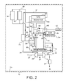
- FIG. 2 is an alternate view of a work machine embodying another aspect of the present invention.
- a work machine 10 powered by an internal combustion engine 12 , which may be mounted on frame 10 a and is preferably of the compression ignition or diesel type producing a rotary output at shaft 13 .
- the rotary output from engine 12 provides the prime mover for work machine 10 and, in addition, provides power through accessory drive connections (not shown) to supply braking and other functions of the work machine.
- the work machine may be an articulated dump truck or a front loader. For each of these work machines, the prime mover duty cycle of the engine 12 is in addition to the many accessory loads supplied by the engine.
- the engine 12 is an air-breathing, fuel-consuming engine that, in the diesel engine form, relies on the compression temperatures of the intake air to ignite a fuel charge producing combustion in individual cylinders, which are not shown to simplify the understanding of the invention.
- the cylinders are connected to a crank shaft (also not shown), to produce the rotary output at output shaft 13 .
- Output shaft 13 is connected to transmissions or other drives (not shown) as appropriate for the work machine 10 .
- exhaust aftertreatment device 24 may take the form of a combination of particulate filtration and/or oxides of nitrogen reduction. Furthermore, the location of exhaust aftertreatment device 24 may be in line 16 upstream of the turbine 18 as appropriate.
- Turbine 18 is connected to and drives a compressor 26 , which receives intake air from ambient ( A ) and pressurizes it for delivery through line 30 and 32 extending to a charge air cooler 34 (CAC), or primary heat exchanger.
- Charge air cooler 34 may take a number of forms but the preferred form of the charge air cooler is an air-to-air cooler, which relies on the temperature of ambient air to cool the intake air that is passed through the charge air cooler. Downstream of the charge air cooler, there is a line 36 extending to an intake manifold 38 , which supplies combustion air to the cylinders for engine 12 .
- a fuel system receives control inputs from an electronic control module 42 (ECM) via line 44 to supply fuel to the individual cylinders of engine 12 in appropriate quantities and at the appropriate time to achieve the proper balance of power, versus efficiency and emissions.
- ECM electronice control module
- Engine 12 in typical fashion, is a liquid cooled engine and has a coolant pump 46 mechanically driven from engine 12 and which supplies liquid coolant through internal passages, which ultimately, are discharged through line 48 and a thermostat 49 to a radiator 50 of the liquid-to-air configuration.
- a line 52 extends from radiator 50 to the inlet of coolant pump 46 .
- the engine 12 is also called upon to supply heat to an operator cab 54 , contained within work machine 10 , and specifically to a cab heater 56 .
- the cab heater 56 is in the form of a liquid-to-air heater and receives engine coolant from engine 12 via line 58 and returns the coolant via line 60 to the inlet of pump 46 .
- a line 62 extends from exhaust line 16 past a valve 64 through an EGR cooler 66 and line 68 to intake line 36 .
- air for combustion is deemed to contain not only ambient air A but a percentage of EGR so that when combustion air flow or fluid flow is mentioned, it may contain varying percentages of EGR. The purpose of this is to provide a selected proportion of nitrogen to the combustion mixture to reduce its temperature and, therefore, the production of oxides of nitrogen.
- an intake air precooler 70 is provided between line 30 and 32 to reduce the temperature within line 32 to a point that is acceptable for the materials used in line 32 and the interstices of the charge air cooler 34 .
- the heat exchanger 70 preferably is a liquid-to-air heat exchanger receiving coolant via line 72 from internal coolant passages downstream of coolant pump 46 for engine 12 .
- a thermostat 74 is located adjacent heat exchanger 70 and controls coolant flow to a line 76 leading to the inlet of coolant pump 46 for engine 12 .
- Heat exchanger 70 provides a precooling function for combustion air delivered to line 32 .
- the excess heat within line 30 is discharged to the liquid coolant passing ultimately to the inlet of coolant pump 46 for engine 12 .
- the thermostat 74 can respond more quickly to changes in temperature so as to provide proper cooling of air passing through heat exchanger 70 .
- the heat exchanger 70 has a minimal bleed flow passing through thermostat 74 to the inlet of pump 46 so as to provide a quick response to changes in temperature.
- thermostat 74 may be replaced by an electronically controlled coolant valve and would be controlled from ECM 42 by line 78 indicated in dashed fashion.
- a bypass 80 for combustion air may be provided around heat exchanger 70 and controlled by valve 82 .
- Valve 82 may receive control inputs from either the ECM or direct control, either of which would respond to temperatures in line 30 so that the temperature is appropriately controlled.
- the control of liquid coolant through heat exchanger 70 is manipulated so as to minimize the adverse impact on the cab heater 56 during low ambient temperature and low engine load conditions. Diesel engines are exceptionally efficient and have very little waste heat, relative to ignited gasoline engines, or other equivalents so that manipulation of the flow through the heat exchanger 70 needs to be controlled to minimize the impact on the heat available to the cab heater 56 .
- the engine 12 in operation provides power to the work machine 10 for propulsion and for accessory loads.
- the adaption of the engine 12 to meet EPA emissions limits causes the temperature of the air compressed by compressor 26 to be heated substantially.
- the heat exchanger 70 extracts heat from the air flow and reduces it to a level manageable for the components of the charge air cooler 34 .
- the thermostat 74 is located adjacent the heat exchanger 70 so as to respond to rapid changes in temperature. This occurs during low ambient or low load conditions in which flow through heat exchanger 70 would cause heat from the coolant stream to transfer to the charge air stream since the charge air stream is cooler than the coolant stream. By providing a bleed flow through thermostat 74 , the thermostat is more readily able to respond to rapid changes in temperature so as to open and close to regulate temperature.
- the optional bypass flow 80 by means of diverter valve 82 and circuit 80 , is used during low ambient and low load conditions so that the heat exchanger 70 does not unnecessarily warm the air flowing to line 32 .
- FIG. 2 shows an alternative form of the work machine of 10 (including frame 10 a ) but shown in an arrangement in which the precooler 70 or secondary heat exchanger is supplied with coolant from a pump other than the engine coolant pump 46 .
- the unaltered components of the work machine are given the same reference characters as those for FIG. 1 .
- the output from radiator 58 feeds the inlet of pump 46 via line 84 and also the inlet to a pump 86 , also driven mechanically by engine 12 .
- Pump 86 supplies liquid coolant to precooler 70 via line 88 and return flow passes to the inlet of radiator 58 via line 90 and line 48 .
- the output of pump 86 also supplies heat generating components 92 and 94 via line 96 .
- the return from heat generating components 92 and 94 passes via line 98 to connect with line 48 leading to the inlet of radiator 58 .
- the heat generating components 92 and 94 may be motor generators of an electrically driven work vehicle 10 in which heat is generated in the process of resisting forward motions through the use of regenerative braking.
- the precooler 70 is in parallel liquid flow relation to the heat generating elements 92 and 94 , which are cooled by radiator 58 .
- an additional radiator may be employed in parallel flow relation to radiator 58 to provide additional cooling for the circuit.
- the precooler 70 enables a reduction in temperature in the inlet 32 to charge air cooler 34 that maintains the elements within their material limits for the flexible interconnecting components and for the internal components of charge air cooler 34 .
Landscapes
- Engineering & Computer Science (AREA)
- Chemical & Material Sciences (AREA)
- Combustion & Propulsion (AREA)
- Mechanical Engineering (AREA)
- General Engineering & Computer Science (AREA)
- Physics & Mathematics (AREA)
- Thermal Sciences (AREA)
- Supercharger (AREA)
Abstract
Description
Claims (10)
Priority Applications (2)
| Application Number | Priority Date | Filing Date | Title |
|---|---|---|---|
| US13/027,988 US8813489B2 (en) | 2011-02-15 | 2011-02-15 | Internal combustion engine charge air cooler precooler |
| JP2012024688A JP2012167670A (en) | 2011-02-15 | 2012-02-08 | Internal combustion engine charge air cooler precooler |
Applications Claiming Priority (1)
| Application Number | Priority Date | Filing Date | Title |
|---|---|---|---|
| US13/027,988 US8813489B2 (en) | 2011-02-15 | 2011-02-15 | Internal combustion engine charge air cooler precooler |
Publications (2)
| Publication Number | Publication Date |
|---|---|
| US20120204555A1 US20120204555A1 (en) | 2012-08-16 |
| US8813489B2 true US8813489B2 (en) | 2014-08-26 |
Family
ID=46635820
Family Applications (1)
| Application Number | Title | Priority Date | Filing Date |
|---|---|---|---|
| US13/027,988 Expired - Fee Related US8813489B2 (en) | 2011-02-15 | 2011-02-15 | Internal combustion engine charge air cooler precooler |
Country Status (2)
| Country | Link |
|---|---|
| US (1) | US8813489B2 (en) |
| JP (1) | JP2012167670A (en) |
Cited By (3)
| Publication number | Priority date | Publication date | Assignee | Title |
|---|---|---|---|---|
| US20150219005A1 (en) * | 2014-01-31 | 2015-08-06 | Halla Visteon Climate Control Corp. | Method of improving charge air condition in air-cooled charge air coolers |
| US10047707B2 (en) | 2015-06-03 | 2018-08-14 | Cnh Industrial America Llc | System and method for cooling charge air and excess fuel for a turbocharged diesel engine |
| US10920656B2 (en) | 2017-06-09 | 2021-02-16 | Pratt & Whitney Canada Corp. | Internal combustion engine cooling system |
Families Citing this family (7)
| Publication number | Priority date | Publication date | Assignee | Title |
|---|---|---|---|---|
| US10630137B2 (en) | 2016-12-14 | 2020-04-21 | Bendix Commerical Vehicle Systems Llc | Front end motor-generator system and modular generator drive apparatus |
| US10640103B2 (en) | 2016-12-14 | 2020-05-05 | Bendix Commercial Vehicle Systems Llc | Front end motor-generator system and hybrid electric vehicle operating method |
| US10532647B2 (en) | 2016-12-14 | 2020-01-14 | Bendix Commercial Vehicle Systems Llc | Front end motor-generator system and hybrid electric vehicle operating method |
| US10220830B2 (en) | 2016-12-14 | 2019-03-05 | Bendix Commercial Vehicle Systems | Front end motor-generator system and hybrid electric vehicle operating method |
| US12553379B2 (en) | 2016-12-14 | 2026-02-17 | Bendix Commercial Vehicle Systems Llc | Front end motor-generator system and hybrid electric vehicle operating method |
| US11807112B2 (en) | 2016-12-14 | 2023-11-07 | Bendix Commercial Vehicle Systems Llc | Front end motor-generator system and hybrid electric vehicle operating method |
| US10543735B2 (en) * | 2016-12-14 | 2020-01-28 | Bendix Commercial Vehicle Systems Llc | Hybrid commercial vehicle thermal management using dynamic heat generator |
Citations (23)
| Publication number | Priority date | Publication date | Assignee | Title |
|---|---|---|---|---|
| US3134371A (en) * | 1962-10-29 | 1964-05-26 | Cooper Bessemer Corp | Cooling system for internal combustion engines |
| US4317439A (en) * | 1979-08-24 | 1982-03-02 | The Garrett Corporation | Cooling system |
| US4352456A (en) * | 1980-06-09 | 1982-10-05 | J. I. Case Company | Cab heating system |
| US5036668A (en) * | 1990-07-03 | 1991-08-06 | Allied-Signal Inc. | Engine intake temperature control system |
| US6510690B2 (en) * | 2000-03-27 | 2003-01-28 | Komatsu Ltd. | Diesel engine with supercharger |
| US20040020204A1 (en) * | 2002-08-01 | 2004-02-05 | Callas James J. | Cooling of engine combustion air |
| US6758266B1 (en) * | 1998-02-27 | 2004-07-06 | Volvo Wheel Loader Ab | Work machine having a hydraulic liquid cooling and heating system |
| US20050006048A1 (en) * | 2003-07-11 | 2005-01-13 | Deere & Company, A Delaware Corporation | Vertical airflow engine cooling system |
| US20060037590A1 (en) * | 2004-08-20 | 2006-02-23 | Teoman Uzkan | Combined aftercooler system with shared fans |
| JP2006299825A (en) * | 2005-04-15 | 2006-11-02 | Hitachi Constr Mach Co Ltd | Warming-up operation system of construction machine |
| US20070227141A1 (en) * | 2006-03-31 | 2007-10-04 | Jiubo Ma | Multi-stage jacket water aftercooler system |
| US20070272173A1 (en) * | 2006-05-15 | 2007-11-29 | Freightliner Llc | Predictive auxiliary load management (PALM) control apparatus and method |
| US20080295811A1 (en) * | 2007-05-31 | 2008-12-04 | Caterpillar Inc. | Engine system having cooled and heated inlet air |
| US20090020079A1 (en) * | 2005-11-10 | 2009-01-22 | BEHRmbH & Co. KG | Circulation system, mixing element |
| US20090050117A1 (en) * | 2006-02-23 | 2009-02-26 | Mack Trucks, Inc. | Charge air cooler arrangement with cooler bypass and method |
| US20100006043A1 (en) * | 2006-10-03 | 2010-01-14 | Zoltan Kardos | Cooling arrangement at a vehicle |
| US20100095909A1 (en) * | 2008-10-22 | 2010-04-22 | Caterpillar Inc. | Engine cooling system onboard diagnostic strategy |
| US20100095908A1 (en) * | 2008-10-17 | 2010-04-22 | Caterpillar Inc. | Multi-thermostat engine cooling system |
| US20110041814A1 (en) * | 2008-04-18 | 2011-02-24 | Zoltan Kardos | Cooling arrangement for a supercharged internal combustion engine |
| US20110088668A1 (en) * | 2008-06-09 | 2011-04-21 | Zoltan Kardos | Arrangement for a supercharged combustion engine concerning coolers for inlet air to and exhaust gases from the engine |
| US20110185991A1 (en) * | 2010-02-01 | 2011-08-04 | Alan Sheidler | Moisture purging in an egr system |
| US8336528B2 (en) * | 2006-07-10 | 2012-12-25 | Calsonic Kansei Corporation | EGR device |
| US20130068202A1 (en) * | 2010-05-25 | 2013-03-21 | Zoltan Kardos | Cooler arrangement for a vehicle powered by a supercharged combustion engine |
-
2011
- 2011-02-15 US US13/027,988 patent/US8813489B2/en not_active Expired - Fee Related
-
2012
- 2012-02-08 JP JP2012024688A patent/JP2012167670A/en active Pending
Patent Citations (23)
| Publication number | Priority date | Publication date | Assignee | Title |
|---|---|---|---|---|
| US3134371A (en) * | 1962-10-29 | 1964-05-26 | Cooper Bessemer Corp | Cooling system for internal combustion engines |
| US4317439A (en) * | 1979-08-24 | 1982-03-02 | The Garrett Corporation | Cooling system |
| US4352456A (en) * | 1980-06-09 | 1982-10-05 | J. I. Case Company | Cab heating system |
| US5036668A (en) * | 1990-07-03 | 1991-08-06 | Allied-Signal Inc. | Engine intake temperature control system |
| US6758266B1 (en) * | 1998-02-27 | 2004-07-06 | Volvo Wheel Loader Ab | Work machine having a hydraulic liquid cooling and heating system |
| US6510690B2 (en) * | 2000-03-27 | 2003-01-28 | Komatsu Ltd. | Diesel engine with supercharger |
| US20040020204A1 (en) * | 2002-08-01 | 2004-02-05 | Callas James J. | Cooling of engine combustion air |
| US20050006048A1 (en) * | 2003-07-11 | 2005-01-13 | Deere & Company, A Delaware Corporation | Vertical airflow engine cooling system |
| US20060037590A1 (en) * | 2004-08-20 | 2006-02-23 | Teoman Uzkan | Combined aftercooler system with shared fans |
| JP2006299825A (en) * | 2005-04-15 | 2006-11-02 | Hitachi Constr Mach Co Ltd | Warming-up operation system of construction machine |
| US20090020079A1 (en) * | 2005-11-10 | 2009-01-22 | BEHRmbH & Co. KG | Circulation system, mixing element |
| US20090050117A1 (en) * | 2006-02-23 | 2009-02-26 | Mack Trucks, Inc. | Charge air cooler arrangement with cooler bypass and method |
| US20070227141A1 (en) * | 2006-03-31 | 2007-10-04 | Jiubo Ma | Multi-stage jacket water aftercooler system |
| US20070272173A1 (en) * | 2006-05-15 | 2007-11-29 | Freightliner Llc | Predictive auxiliary load management (PALM) control apparatus and method |
| US8336528B2 (en) * | 2006-07-10 | 2012-12-25 | Calsonic Kansei Corporation | EGR device |
| US20100006043A1 (en) * | 2006-10-03 | 2010-01-14 | Zoltan Kardos | Cooling arrangement at a vehicle |
| US20080295811A1 (en) * | 2007-05-31 | 2008-12-04 | Caterpillar Inc. | Engine system having cooled and heated inlet air |
| US20110041814A1 (en) * | 2008-04-18 | 2011-02-24 | Zoltan Kardos | Cooling arrangement for a supercharged internal combustion engine |
| US20110088668A1 (en) * | 2008-06-09 | 2011-04-21 | Zoltan Kardos | Arrangement for a supercharged combustion engine concerning coolers for inlet air to and exhaust gases from the engine |
| US20100095908A1 (en) * | 2008-10-17 | 2010-04-22 | Caterpillar Inc. | Multi-thermostat engine cooling system |
| US20100095909A1 (en) * | 2008-10-22 | 2010-04-22 | Caterpillar Inc. | Engine cooling system onboard diagnostic strategy |
| US20110185991A1 (en) * | 2010-02-01 | 2011-08-04 | Alan Sheidler | Moisture purging in an egr system |
| US20130068202A1 (en) * | 2010-05-25 | 2013-03-21 | Zoltan Kardos | Cooler arrangement for a vehicle powered by a supercharged combustion engine |
Cited By (3)
| Publication number | Priority date | Publication date | Assignee | Title |
|---|---|---|---|---|
| US20150219005A1 (en) * | 2014-01-31 | 2015-08-06 | Halla Visteon Climate Control Corp. | Method of improving charge air condition in air-cooled charge air coolers |
| US10047707B2 (en) | 2015-06-03 | 2018-08-14 | Cnh Industrial America Llc | System and method for cooling charge air and excess fuel for a turbocharged diesel engine |
| US10920656B2 (en) | 2017-06-09 | 2021-02-16 | Pratt & Whitney Canada Corp. | Internal combustion engine cooling system |
Also Published As
| Publication number | Publication date |
|---|---|
| JP2012167670A (en) | 2012-09-06 |
| US20120204555A1 (en) | 2012-08-16 |
Similar Documents
| Publication | Publication Date | Title |
|---|---|---|
| US8813489B2 (en) | Internal combustion engine charge air cooler precooler | |
| US8015954B2 (en) | Cooling fan arrangement at a vehicle | |
| US5740786A (en) | Internal combustion engine with an exhaust gas recirculation system | |
| CN103370511B (en) | Internal-combustion engine | |
| JP5754755B2 (en) | Engine arrangement with charge air cooler and EGR system | |
| US8176736B2 (en) | EGR apparatuses, systems, and methods | |
| US6955162B2 (en) | Internal combustion engine with pressure boosted exhaust gas recirculation | |
| CN102057142B (en) | Arrangement for a supercharged combustion engine | |
| US7040303B2 (en) | Combined aftercooler system with shared fans | |
| US20100180584A1 (en) | Drive train, particularly for trucks and rail vehicles | |
| US8443789B2 (en) | Exhaust gas recirculation system for an internal combustion engine | |
| CN102400773B (en) | There is motor vehicles and the electromotor operation method of electromotor | |
| US20130312418A1 (en) | System for converting thermal energy to mechanical energy in a vehicle | |
| GB2473821A (en) | Exhaust gas recirculation system with multiple coolers | |
| JP2011503436A (en) | Supercharged combustion engine configuration | |
| KR20130081664A (en) | Cooler arrangement for a vehicle powered by a supercharged combustion engine | |
| KR101323776B1 (en) | Arrangement for cooling of recirculated exhaust gases in a combustion engine | |
| JP2009079487A (en) | Engine supercharger | |
| KR20110135968A (en) | Recirculation exhaust gas cooling device of combustion engine | |
| CN103511051A (en) | Liquid-cooled internal combustion engine with afterrun cooling, and method for operating internal combustion engine of said type | |
| US7886726B2 (en) | Arrangement for recirculation of exhaust gases of a supercharged internal combustion engine | |
| EP2574753A1 (en) | Cooling system for two-stage charged engines | |
| WO2005116438A1 (en) | An arrangement for recirculation of exhaust gases of a super-charged internal combustion engine | |
| KR20210000299A (en) | Method for operating an internal combustion engine, internal combustion engine and motor vehicle | |
| CN105849384A (en) | Internal combustion engine system |
Legal Events
| Date | Code | Title | Description |
|---|---|---|---|
| AS | Assignment |
Owner name: DEERE & COMPANY, ILLINOIS Free format text: ASSIGNMENT OF ASSIGNORS INTEREST;ASSIGNORS:DIDELOT, DAVID R.;SEND, DOUGLAS J.;DYLHOFF, JONATHAN A.;AND OTHERS;REEL/FRAME:025812/0549 Effective date: 20110214 |
|
| FEPP | Fee payment procedure |
Free format text: PAYOR NUMBER ASSIGNED (ORIGINAL EVENT CODE: ASPN); ENTITY STATUS OF PATENT OWNER: LARGE ENTITY |
|
| FEPP | Fee payment procedure |
Free format text: MAINTENANCE FEE REMINDER MAILED (ORIGINAL EVENT CODE: REM.) |
|
| LAPS | Lapse for failure to pay maintenance fees |
Free format text: PATENT EXPIRED FOR FAILURE TO PAY MAINTENANCE FEES (ORIGINAL EVENT CODE: EXP.); ENTITY STATUS OF PATENT OWNER: LARGE ENTITY |
|
| STCH | Information on status: patent discontinuation |
Free format text: PATENT EXPIRED DUE TO NONPAYMENT OF MAINTENANCE FEES UNDER 37 CFR 1.362 |
|
| FP | Lapsed due to failure to pay maintenance fee |
Effective date: 20180826 |