US8808880B2 - Condensed-cyclic compound, organic light-emitting device comprising the same, and flat panel display apparatus - Google Patents
Condensed-cyclic compound, organic light-emitting device comprising the same, and flat panel display apparatus Download PDFInfo
- Publication number
- US8808880B2 US8808880B2 US13/243,959 US201113243959A US8808880B2 US 8808880 B2 US8808880 B2 US 8808880B2 US 201113243959 A US201113243959 A US 201113243959A US 8808880 B2 US8808880 B2 US 8808880B2
- Authority
- US
- United States
- Prior art keywords
- group
- substituted
- unsubstituted
- condensed
- cyclic compound
- Prior art date
- Legal status (The legal status is an assumption and is not a legal conclusion. Google has not performed a legal analysis and makes no representation as to the accuracy of the status listed.)
- Active, expires
Links
- 0 C.C.C1=CC2=C(C=C1)CCC2.CC.CC.CC[Y](CC)C[Ar].[1*]C1([2*])CCC2=C1/C=C\C=C/2.[3*]C.[4*]C Chemical compound C.C.C1=CC2=C(C=C1)CCC2.CC.CC.CC[Y](CC)C[Ar].[1*]C1([2*])CCC2=C1/C=C\C=C/2.[3*]C.[4*]C 0.000 description 28
- RWTWTKHMBKFPHA-UHFFFAOYSA-N CC1(C)C2=C(C=C3C=CC=CC3=C2)C2=C1C=C(N(C1=CC=CC=C1)C1=CC=C(C3=CC4=C(C=C3)N(C3=CC=CC=C3)C3=C4C4=C(C=CC=C4)C=C3)C=C1)C=C2 Chemical compound CC1(C)C2=C(C=C3C=CC=CC3=C2)C2=C1C=C(N(C1=CC=CC=C1)C1=CC=C(C3=CC4=C(C=C3)N(C3=CC=CC=C3)C3=C4C4=C(C=CC=C4)C=C3)C=C1)C=C2 RWTWTKHMBKFPHA-UHFFFAOYSA-N 0.000 description 3
- CUJXBIJIHVUPPY-UHFFFAOYSA-N C.C1=CC2=C(C=C1)CCC2.CC.CC.CC Chemical compound C.C1=CC2=C(C=C1)CCC2.CC.CC.CC CUJXBIJIHVUPPY-UHFFFAOYSA-N 0.000 description 2
- BTPUVPZQLYARBT-UHFFFAOYSA-N C1=CC=C(N(C2=CC=C(C3=CC4=C(C=C3)N(C3=CC=CC=C3)C3=C4C=CC=C3)C=C2)C2=CC=C3C(=C2)C(C2=CC=CC=C2)(C2=CC=CC=C2)C2=C3C=CC=C2)C=C1 Chemical compound C1=CC=C(N(C2=CC=C(C3=CC4=C(C=C3)N(C3=CC=CC=C3)C3=C4C=CC=C3)C=C2)C2=CC=C3C(=C2)C(C2=CC=CC=C2)(C2=CC=CC=C2)C2=C3C=CC=C2)C=C1 BTPUVPZQLYARBT-UHFFFAOYSA-N 0.000 description 2
- IQIATBAYBXGSNR-UHFFFAOYSA-N CC1(C)C2=C(C=C3C=CC=CC3=C2)C2=C1C=C(N(C1=CC=CC=C1)C1=CC3=C(C=C1)N(C1=CC=CC=C1)C1=C3C3=C(C=CC=C3)C=C1)C=C2.CC1(C)C2=C(C=C3C=CC=CC3=C2)C2=C1C=C(N(C1=CC=CC=C1)C1=CC3=C(C=C1)N(C1=CC=CC=C1)C1=C3C=C3C=CC=CC3=C1)C=C2.CC1(C)C2=C(C=CC(N(C3=CC=CC=C3)C3=CC4=C(C=C3)N(C3=CC=CC=C3)C3=C4C=C4C=CC=CC4=C3)=C2)C2=C1C1=C(C=CC=C1)C=C2 Chemical compound CC1(C)C2=C(C=C3C=CC=CC3=C2)C2=C1C=C(N(C1=CC=CC=C1)C1=CC3=C(C=C1)N(C1=CC=CC=C1)C1=C3C3=C(C=CC=C3)C=C1)C=C2.CC1(C)C2=C(C=C3C=CC=CC3=C2)C2=C1C=C(N(C1=CC=CC=C1)C1=CC3=C(C=C1)N(C1=CC=CC=C1)C1=C3C=C3C=CC=CC3=C1)C=C2.CC1(C)C2=C(C=CC(N(C3=CC=CC=C3)C3=CC4=C(C=C3)N(C3=CC=CC=C3)C3=C4C=C4C=CC=CC4=C3)=C2)C2=C1C1=C(C=CC=C1)C=C2 IQIATBAYBXGSNR-UHFFFAOYSA-N 0.000 description 2
- OALUCKZSNHCPKS-UHFFFAOYSA-N CC1(C)C2=C(C=C3C=CC=CC3=C2)C2=C1C=C(N(C1=CC=CC=C1)C1=CC=C(C3=CC4=C(C=C3)N(C3=CC=CC=C3)C3=C4C4=C(C=CC=C4)C=C3)C=C1)C=C2.CC1(C)C2=C(C=C3C=CC=CC3=C2)C2=C1C=C(N(C1=CC=CC=C1)C1=CC=C(C3=CC4=C(C=C3)N(C3=CC=CC=C3)C3=C4C=C4C=CC=CC4=C3)C=C1)C=C2.CC1(C)C2=C(C=CC(N(C3=CC=CC=C3)C3=CC=C(C4=CC5=C(C=C4)N(C4=CC=CC=C4)C4=C5C5=C(C=CC=C5)C=C4)C=C3)=C2)C2=C1C1=C(C=CC=C1)C=C2.CC1(C)C2=C(C=CC(N(C3=CC=CC=C3)C3=CC=C(C4=CC5=C(C=C4)N(C4=CC=CC=C4)C4=C5C=C5C=CC=CC5=C4)C=C3)=C2)C2=C1C1=C(C=CC=C1)C=C2 Chemical compound CC1(C)C2=C(C=C3C=CC=CC3=C2)C2=C1C=C(N(C1=CC=CC=C1)C1=CC=C(C3=CC4=C(C=C3)N(C3=CC=CC=C3)C3=C4C4=C(C=CC=C4)C=C3)C=C1)C=C2.CC1(C)C2=C(C=C3C=CC=CC3=C2)C2=C1C=C(N(C1=CC=CC=C1)C1=CC=C(C3=CC4=C(C=C3)N(C3=CC=CC=C3)C3=C4C=C4C=CC=CC4=C3)C=C1)C=C2.CC1(C)C2=C(C=CC(N(C3=CC=CC=C3)C3=CC=C(C4=CC5=C(C=C4)N(C4=CC=CC=C4)C4=C5C5=C(C=CC=C5)C=C4)C=C3)=C2)C2=C1C1=C(C=CC=C1)C=C2.CC1(C)C2=C(C=CC(N(C3=CC=CC=C3)C3=CC=C(C4=CC5=C(C=C4)N(C4=CC=CC=C4)C4=C5C=C5C=CC=CC5=C4)C=C3)=C2)C2=C1C1=C(C=CC=C1)C=C2 OALUCKZSNHCPKS-UHFFFAOYSA-N 0.000 description 2
- QPXASIPKENWONO-UHFFFAOYSA-N CC1(C)C2=C(C=C3C=CC=CC3=C2)C2=C1C=C(N(C1=CC=CC=C1)C1=CC=C(C3=CC4=C(C=C3)N(C3=CC=CC=C3)C3=C4C=C4C=CC=CC4=C3)C=C1)C=C2.CC1(C)C2=C(C=CC(N(C3=CC=CC=C3)C3=CC=C(C4=CC5=C(C=C4)N(C4=CC=CC=C4)C4=C5C5=C(C=CC=C5)C=C4)C=C3)=C2)C2=C1C1=C(C=CC=C1)C=C2.CC1(C)C2=C(C=CC(N(C3=CC=CC=C3)C3=CC=C(C4=CC5=C(C=C4)N(C4=CC=CC=C4)C4=C5C=C5C=CC=CC5=C4)C=C3)=C2)C2=C1C1=C(C=CC=C1)C=C2.CC1(C)C2=CC(N(C3=CC4=C(C=C3)N(C3=CC=CC=C3)C3=C4C=C4C=CC=CC4=C3)C3=CC4=C(C=C3)C3=C(C=C5C=CC=CC5=C3)C4(C)C)=CC=C2C2=C1C=CC=C2 Chemical compound CC1(C)C2=C(C=C3C=CC=CC3=C2)C2=C1C=C(N(C1=CC=CC=C1)C1=CC=C(C3=CC4=C(C=C3)N(C3=CC=CC=C3)C3=C4C=C4C=CC=CC4=C3)C=C1)C=C2.CC1(C)C2=C(C=CC(N(C3=CC=CC=C3)C3=CC=C(C4=CC5=C(C=C4)N(C4=CC=CC=C4)C4=C5C5=C(C=CC=C5)C=C4)C=C3)=C2)C2=C1C1=C(C=CC=C1)C=C2.CC1(C)C2=C(C=CC(N(C3=CC=CC=C3)C3=CC=C(C4=CC5=C(C=C4)N(C4=CC=CC=C4)C4=C5C=C5C=CC=CC5=C4)C=C3)=C2)C2=C1C1=C(C=CC=C1)C=C2.CC1(C)C2=CC(N(C3=CC4=C(C=C3)N(C3=CC=CC=C3)C3=C4C=C4C=CC=CC4=C3)C3=CC4=C(C=C3)C3=C(C=C5C=CC=CC5=C3)C4(C)C)=CC=C2C2=C1C=CC=C2 QPXASIPKENWONO-UHFFFAOYSA-N 0.000 description 2
- ZIDSEEZJOCWSNJ-UHFFFAOYSA-N CC1(C)C2=C(C=CC(N(C3=CC=C(C4=CC=CC=C4)C=C3)C3=CC4=C(C=C3)N(C3=CC=CC=C3)C3=C4C4=C(C=CC=C4)C=C3)=C2)C2=C1C1=C(C=CC=C1)C=C2.CC1(C)C2=C(C=CC(N(C3=CC=C(C4=CC=CC=C4)C=C3)C3=CC4=C(C=C3)N(C3=CC=CC=C3)C3=C4C=C4C=CC=CC4=C3)=C2)C2=C1C1=C(C=CC=C1)C=C2.CC1(C)C2=C(C=CC(N(C3=CC=CC=C3)C3=CC4=C(C=C3)N(C3=CC=CC=C3)C3=C4C4=C(C=CC=C4)C=C3)=C2)C2=C1C1=C(C=CC=C1)C=C2 Chemical compound CC1(C)C2=C(C=CC(N(C3=CC=C(C4=CC=CC=C4)C=C3)C3=CC4=C(C=C3)N(C3=CC=CC=C3)C3=C4C4=C(C=CC=C4)C=C3)=C2)C2=C1C1=C(C=CC=C1)C=C2.CC1(C)C2=C(C=CC(N(C3=CC=C(C4=CC=CC=C4)C=C3)C3=CC4=C(C=C3)N(C3=CC=CC=C3)C3=C4C=C4C=CC=CC4=C3)=C2)C2=C1C1=C(C=CC=C1)C=C2.CC1(C)C2=C(C=CC(N(C3=CC=CC=C3)C3=CC4=C(C=C3)N(C3=CC=CC=C3)C3=C4C4=C(C=CC=C4)C=C3)=C2)C2=C1C1=C(C=CC=C1)C=C2 ZIDSEEZJOCWSNJ-UHFFFAOYSA-N 0.000 description 2
- FNVMLDFVARZEBG-UHFFFAOYSA-N CC1(C)C2=CC(N(C3=CC=CC=C3)C3=CC4=C(C=C3)N(C3=CC=CC=C3)C3=C4C=CC=C3)=CC=C2C2=C1C=CC=C2 Chemical compound CC1(C)C2=CC(N(C3=CC=CC=C3)C3=CC4=C(C=C3)N(C3=CC=CC=C3)C3=C4C=CC=C3)=CC=C2C2=C1C=CC=C2 FNVMLDFVARZEBG-UHFFFAOYSA-N 0.000 description 2
- YRFLSIHOQYPRGD-UHFFFAOYSA-N CC1(C)C2=CC=CC=C2C2=C1C=C(C1=CC=C(N(C3=CC=C4C(=C3)C3=C(C=CC=C3)N4C3=CC=CC=C3)C3=CC4=C(C=C3)N(C3=CC=CC=C3)C3=C4C=CC=C3)C=C1)C=C2 Chemical compound CC1(C)C2=CC=CC=C2C2=C1C=C(C1=CC=C(N(C3=CC=C4C(=C3)C3=C(C=CC=C3)N4C3=CC=CC=C3)C3=CC4=C(C=C3)N(C3=CC=CC=C3)C3=C4C=CC=C3)C=C1)C=C2 YRFLSIHOQYPRGD-UHFFFAOYSA-N 0.000 description 2
- JHWOBMLXFHNNEP-UHFFFAOYSA-N *.B.B.BrC1=CC=C(C2=C/C3=C(\C=C/2)N(C2=CC=CC=C2)C2=C3C=C3C=CC=CC3=C2)C=C1.CC1(C)C2=C(C=C3C=CC=CC3=C2)C2=C/C=C(N(C3=CC=CC=C3)C3=CC=C(C4=CC5=C(C=C4)N(C4=CC=CC=C4)C4=CC6=C(C=CC=C6)C=C45)C=C3)/C=C\21.CC1(C)C2=C(C=C3C=CC=CC3=C2)C2=C\C=C(NC3=CC=CC=C3)/C=C\21.CC1(C)C2=CC(NC3=CC=CC=C3)=CC=C2C2=C1C=C1C=CC=CC1=C2 Chemical compound *.B.B.BrC1=CC=C(C2=C/C3=C(\C=C/2)N(C2=CC=CC=C2)C2=C3C=C3C=CC=CC3=C2)C=C1.CC1(C)C2=C(C=C3C=CC=CC3=C2)C2=C/C=C(N(C3=CC=CC=C3)C3=CC=C(C4=CC5=C(C=C4)N(C4=CC=CC=C4)C4=CC6=C(C=CC=C6)C=C45)C=C3)/C=C\21.CC1(C)C2=C(C=C3C=CC=CC3=C2)C2=C\C=C(NC3=CC=CC=C3)/C=C\21.CC1(C)C2=CC(NC3=CC=CC=C3)=CC=C2C2=C1C=C1C=CC=CC1=C2 JHWOBMLXFHNNEP-UHFFFAOYSA-N 0.000 description 1
- TXZQLMWEHUQEBU-REZQDPELSA-N *.BrC1=CC=C(C2=CC3=C(C=C2)N(C2=CC=CC=C2)C2=C3C3=C(C=CC=C3)C=C2)C=C1.CC1(C)C2=C(C=CC3=C2C=CC=C3)C2=C/C=C(N(C3=CC=CC=C3)C3=CC=C(C4=CC5=C(C=C4)N(C4=CC=CC=C4)C4=CC=C6C=CC=CC6=C45)C=C3)/C=C\21.CC1(C)C2=C(C=CC3=C2C=CC=C3)C2=C\C=C(NC3=CC=CC=C3)/C=C\21.CC1(C)C2=CC(NC3=CC=CC=C3)=CC=C2C2=C1C1=C(C=CC=C1)C=C2.[2HH].[2HH] Chemical compound *.BrC1=CC=C(C2=CC3=C(C=C2)N(C2=CC=CC=C2)C2=C3C3=C(C=CC=C3)C=C2)C=C1.CC1(C)C2=C(C=CC3=C2C=CC=C3)C2=C/C=C(N(C3=CC=CC=C3)C3=CC=C(C4=CC5=C(C=C4)N(C4=CC=CC=C4)C4=CC=C6C=CC=CC6=C45)C=C3)/C=C\21.CC1(C)C2=C(C=CC3=C2C=CC=C3)C2=C\C=C(NC3=CC=CC=C3)/C=C\21.CC1(C)C2=CC(NC3=CC=CC=C3)=CC=C2C2=C1C1=C(C=CC=C1)C=C2.[2HH].[2HH] TXZQLMWEHUQEBU-REZQDPELSA-N 0.000 description 1
- SHPYRIFNNBUFPC-UHFFFAOYSA-N *.BrC1=CC=C(C2=CC3=C(C=C2)N(C2=CC=CC=C2)C2=C3C=C3C=CC=CC3=C2)C=C1.BrC1=CC=C(C2=CC3=C(C=C2)NC2=C3C=C3C=CC=CC3=C2)C=C1.CC(C)(O)C1=C(C2=CC=C(Br)C=C2)C=C2C=CC=CC2=C1.CC1(C)C2=C(C=C3C=CC=CC3=C2)C2=C\C=C(Br)/C=C\21.NC1=CC=CC=C1.O=[N+]([O-])C1=CC=C(Br)C=C1C1=CC=C2/C=C\C=C/C2=C1.O=[N+]([O-])C1=CC=C(C2=CC=C(Br)C=C2)C=C1C1=CC=C2/C=C\C=C/C2=C1.OB(O)C1=CC=C(Br)C=C1.[BH4-].[BH5-2].[CH-3].[CH2-2].[CH3-] Chemical compound *.BrC1=CC=C(C2=CC3=C(C=C2)N(C2=CC=CC=C2)C2=C3C=C3C=CC=CC3=C2)C=C1.BrC1=CC=C(C2=CC3=C(C=C2)NC2=C3C=C3C=CC=CC3=C2)C=C1.CC(C)(O)C1=C(C2=CC=C(Br)C=C2)C=C2C=CC=CC2=C1.CC1(C)C2=C(C=C3C=CC=CC3=C2)C2=C\C=C(Br)/C=C\21.NC1=CC=CC=C1.O=[N+]([O-])C1=CC=C(Br)C=C1C1=CC=C2/C=C\C=C/C2=C1.O=[N+]([O-])C1=CC=C(C2=CC=C(Br)C=C2)C=C1C1=CC=C2/C=C\C=C/C2=C1.OB(O)C1=CC=C(Br)C=C1.[BH4-].[BH5-2].[CH-3].[CH2-2].[CH3-] SHPYRIFNNBUFPC-UHFFFAOYSA-N 0.000 description 1
- ROEOSOYDYZCEMB-UHFFFAOYSA-N B.B.BrC1=CC=C(C2=CC3=C(C=C2)N(C2=CC=CC=C2)C2=C3C3=C(C=CC=C3)C=C2)C=C1.C.CC(C)(O)C1=C(C2=CC=C(Br)C=C2)C=C2C=CC=CC2=C1.CC1(C)C2=C(C=C3C=CC=CC3=C2)C2=C\C=C(Br)/C=C\21.CC1(C)C2=C(C=C3C=CC=CC3=C2)C2=C\C=C(NC3=CC=CC=C3)/C=C\21.CC1(C)C2=C(C=C3C=CC=CC3=C2)C2=C\C=C(NC3=CC=CC=C3)/C=C\21.NC1=CC=CC=C1.[BH4-].[BH5-2] Chemical compound B.B.BrC1=CC=C(C2=CC3=C(C=C2)N(C2=CC=CC=C2)C2=C3C3=C(C=CC=C3)C=C2)C=C1.C.CC(C)(O)C1=C(C2=CC=C(Br)C=C2)C=C2C=CC=CC2=C1.CC1(C)C2=C(C=C3C=CC=CC3=C2)C2=C\C=C(Br)/C=C\21.CC1(C)C2=C(C=C3C=CC=CC3=C2)C2=C\C=C(NC3=CC=CC=C3)/C=C\21.CC1(C)C2=C(C=C3C=CC=CC3=C2)C2=C\C=C(NC3=CC=CC=C3)/C=C\21.NC1=CC=CC=C1.[BH4-].[BH5-2] ROEOSOYDYZCEMB-UHFFFAOYSA-N 0.000 description 1
- BQZVBHLFKMATPA-UHFFFAOYSA-N B.CC1(C)C2=C(C=CC(NC3=CC=CC=C3)=C2)C2=CC=C3/C=C\C=C/C3=C21.CC1(C)C2=C(C=CC3=C2C=CC=C3)C2=C/C=C(N(C3=CC=CC=C3)C3=CC4=C(C=C3)N(C3=CC=CC=C3)C3=CC=CC=C34)/C=C\21.IC1=CC2=C(C=C1)N(C1=CC=CC=C1)C1=C2C=CC=C1 Chemical compound B.CC1(C)C2=C(C=CC(NC3=CC=CC=C3)=C2)C2=CC=C3/C=C\C=C/C3=C21.CC1(C)C2=C(C=CC3=C2C=CC=C3)C2=C/C=C(N(C3=CC=CC=C3)C3=CC4=C(C=C3)N(C3=CC=CC=C3)C3=CC=CC=C34)/C=C\21.IC1=CC2=C(C=C1)N(C1=CC=CC=C1)C1=C2C=CC=C1 BQZVBHLFKMATPA-UHFFFAOYSA-N 0.000 description 1
- AADSPCIFCKARRD-PPQSCVLNSA-N BN=P.C1=CC=C(N(C2=CC=C(C3=CC=C(N(C4=CC=CC=C4)C4=C5C=CC=CC5=CC=C4)C=C3)C=C2)C2=CC=CC3=C2C=CC=C3)C=C1.CC1=CC=CC(N(C2=CC=CC=C2)C2=CC=C(C3=CC=C(N(C4=CC=CC=C4)C4=CC(C)=CC=C4)C=C3)C=C2)=C1.[2H]P[3H] Chemical compound BN=P.C1=CC=C(N(C2=CC=C(C3=CC=C(N(C4=CC=CC=C4)C4=C5C=CC=CC5=CC=C4)C=C3)C=C2)C2=CC=CC3=C2C=CC=C3)C=C1.CC1=CC=CC(N(C2=CC=CC=C2)C2=CC=C(C3=CC=C(N(C4=CC=CC=C4)C4=CC(C)=CC=C4)C=C3)C=C2)=C1.[2H]P[3H] AADSPCIFCKARRD-PPQSCVLNSA-N 0.000 description 1
- ORYGFLDNUPKQBM-UHFFFAOYSA-N BrC1=CC2=C(C=C1)C1=C\C=C/C=C\1C2(C1=CC=CC=C1)C1=CC=CC=C1.BrC1=CC=C(C2=CC3=C(C=C2)N(C2=CC=CC=C2)C2=C3/C=C\C=C/2)C=C1.C1=CC=C(CC2=CC3=C(C=C2)C2=C/C=C/C=C\2C3(C2=CC=CC=C2)C2=CC=CC=C2)C=C1.IC1=CC2=C(C=C1)N(C1=CC=CC=C1)C1=C2C=CC=C1.O=C1C2=CC=CC=C2C2=C1C=C(Br)C=C2.OB(O)C1=CC=C(Br)C=C1.OC1(C2=CC=CC=C2)C2=CC=CC=C2C2=C1C=C(Br)C=C2 Chemical compound BrC1=CC2=C(C=C1)C1=C\C=C/C=C\1C2(C1=CC=CC=C1)C1=CC=CC=C1.BrC1=CC=C(C2=CC3=C(C=C2)N(C2=CC=CC=C2)C2=C3/C=C\C=C/2)C=C1.C1=CC=C(CC2=CC3=C(C=C2)C2=C/C=C/C=C\2C3(C2=CC=CC=C2)C2=CC=CC=C2)C=C1.IC1=CC2=C(C=C1)N(C1=CC=CC=C1)C1=C2C=CC=C1.O=C1C2=CC=CC=C2C2=C1C=C(Br)C=C2.OB(O)C1=CC=C(Br)C=C1.OC1(C2=CC=CC=C2)C2=CC=CC=C2C2=C1C=C(Br)C=C2 ORYGFLDNUPKQBM-UHFFFAOYSA-N 0.000 description 1
- FMIGILPNJDSFJP-UHFFFAOYSA-N BrC1=CC=C(C2=CC3=C(C=C2)N(C2=CC=CC=C2)C2=C3C3=C(C=CC=C3)C=C2)C=C1.BrC1=CC=C(C2=CC3=C(C=C2)NC2=C3C3=C(C=CC=C3)C=C2)C=C1.C.O=[N+]([O-])C1=CC=C(Br)C=C1C1=CC=CC2=C1C=CC=C2.O=[N+]([O-])C1=CC=C(C2=CC=C(Br)C=C2)C=C1C1=CC=CC2=C1C=CC=C2.OB(O)C1=CC=C(Br)C=C1.[CH-3].[CH2-2].[CH3-] Chemical compound BrC1=CC=C(C2=CC3=C(C=C2)N(C2=CC=CC=C2)C2=C3C3=C(C=CC=C3)C=C2)C=C1.BrC1=CC=C(C2=CC3=C(C=C2)NC2=C3C3=C(C=CC=C3)C=C2)C=C1.C.O=[N+]([O-])C1=CC=C(Br)C=C1C1=CC=CC2=C1C=CC=C2.O=[N+]([O-])C1=CC=C(C2=CC=C(Br)C=C2)C=C1C1=CC=CC2=C1C=CC=C2.OB(O)C1=CC=C(Br)C=C1.[CH-3].[CH2-2].[CH3-] FMIGILPNJDSFJP-UHFFFAOYSA-N 0.000 description 1
- MCRQSHLSKVKUSJ-UHFFFAOYSA-N Brc(cc1)ccc1-c(cc1)cc(c2c3ccc4c2cccc4)c1[n]3-c1ccccc1 Chemical compound Brc(cc1)ccc1-c(cc1)cc(c2c3ccc4c2cccc4)c1[n]3-c1ccccc1 MCRQSHLSKVKUSJ-UHFFFAOYSA-N 0.000 description 1
- WIILIWQBXRTRBI-UHFFFAOYSA-N C.C.C1=CC2=C(C=C1)C=C(N1C3=C(C=CC=C3)C3=C1C1=C(C=CC=C1)C=C3)C=C2.C1=CC2=CC3=C(C=C2C=C1)N(C1=CC2=C(C=CC=C2)C=C1)C1=C3C=CC=C1.C1=CC=C(N2C3=C(C=CC=C3)C3=C2C2=C(C=CC=C2)C=C3)C=C1.C1=CC=C(N2C3=C(C=CC=C3)C3=C2C=C2C=CC=CC2=C3)C=C1.C1=CC=C(N2C3=C(C=CC=C3)C3=C2C=CC2=C3C=CC=C2)C=C1.CC.CC.CC.CC.CC.CC.CC.CC.CC.CC.CC.CC.CC.CC.CC Chemical compound C.C.C1=CC2=C(C=C1)C=C(N1C3=C(C=CC=C3)C3=C1C1=C(C=CC=C1)C=C3)C=C2.C1=CC2=CC3=C(C=C2C=C1)N(C1=CC2=C(C=CC=C2)C=C1)C1=C3C=CC=C1.C1=CC=C(N2C3=C(C=CC=C3)C3=C2C2=C(C=CC=C2)C=C3)C=C1.C1=CC=C(N2C3=C(C=CC=C3)C3=C2C=C2C=CC=CC2=C3)C=C1.C1=CC=C(N2C3=C(C=CC=C3)C3=C2C=CC2=C3C=CC=C2)C=C1.CC.CC.CC.CC.CC.CC.CC.CC.CC.CC.CC.CC.CC.CC.CC WIILIWQBXRTRBI-UHFFFAOYSA-N 0.000 description 1
- IDLWJGYBZCJXQV-UHFFFAOYSA-N C.C.C1=CC2=C(C=C1)C=C(N1C3=C(C=CC=C3)C3=C1C=CC1=C3C=CC=C1)C=C2.CC.CC.CC.CC.CC.CC.CC.CC.CC.CC.CC.CC.CC.CC.CC.CCN1C2=C(C=CC=C2)C2=C1C=C1C=CC=CC1=C2.CN1C2=C(C=CC=C2)C2=C1C1=C(C=CC=C1)C=C2.CN1C2=C(C=CC=C2)C2=C1C=C1C=CC=CC1=C2.CN1C2=C(C=CC=C2)C2=C1C=CC1=C2C=CC=C1 Chemical compound C.C.C1=CC2=C(C=C1)C=C(N1C3=C(C=CC=C3)C3=C1C=CC1=C3C=CC=C1)C=C2.CC.CC.CC.CC.CC.CC.CC.CC.CC.CC.CC.CC.CC.CC.CC.CCN1C2=C(C=CC=C2)C2=C1C=C1C=CC=CC1=C2.CN1C2=C(C=CC=C2)C2=C1C1=C(C=CC=C1)C=C2.CN1C2=C(C=CC=C2)C2=C1C=C1C=CC=CC1=C2.CN1C2=C(C=CC=C2)C2=C1C=CC1=C2C=CC=C1 IDLWJGYBZCJXQV-UHFFFAOYSA-N 0.000 description 1
- OYANNAUGPSWRSB-UHFFFAOYSA-M C.C.C1=CC=C(N2C3=CC=CC=C3C3=C2C=CC=C3)C=C1.CC1(C)C2=CC=CC=C2C2=C1C=C(Br)C=C2.CC1(C)C2=CC=CC=C2C2=C1C=C(NC1=CC=CC=C1)C=C2.CC1(C)C2=CC=CC=C2C2=C1C=C(NC1=CC=CC=C1)C=C2.F.F.IC1=CC2=C(C=C1)N(C1=CC=CC=C1)C1=C2C=CC=C1.IC1=CC2=C(C=C1)N(C1=CC=CC=C1)C1=C2C=CC=C1.IC1=CC=CC=C1.NC1=CC=CC=C1.[C+]1=CC2=C(C=C1)C1=C(/C=C\C=C/1)C2.[F-] Chemical compound C.C.C1=CC=C(N2C3=CC=CC=C3C3=C2C=CC=C3)C=C1.CC1(C)C2=CC=CC=C2C2=C1C=C(Br)C=C2.CC1(C)C2=CC=CC=C2C2=C1C=C(NC1=CC=CC=C1)C=C2.CC1(C)C2=CC=CC=C2C2=C1C=C(NC1=CC=CC=C1)C=C2.F.F.IC1=CC2=C(C=C1)N(C1=CC=CC=C1)C1=C2C=CC=C1.IC1=CC2=C(C=C1)N(C1=CC=CC=C1)C1=C2C=CC=C1.IC1=CC=CC=C1.NC1=CC=CC=C1.[C+]1=CC2=C(C=C1)C1=C(/C=C\C=C/1)C2.[F-] OYANNAUGPSWRSB-UHFFFAOYSA-M 0.000 description 1
- QOWJKIKOLDVWHQ-UHFFFAOYSA-N C.C1=CC2=C(C=C1)C1=C(C=C2)C2=C(C=CC=C2)S1.C1=CC2=C(C=C1)C1=C(C=C2)SC2=C1C=CC=C2.C1=CC2=CC3=C(C=C2C=C1)C1=C(C=CC=C1)S3.CC.CC.CC.CC.CC.CC.CC.CC.CC Chemical compound C.C1=CC2=C(C=C1)C1=C(C=C2)C2=C(C=CC=C2)S1.C1=CC2=C(C=C1)C1=C(C=C2)SC2=C1C=CC=C2.C1=CC2=CC3=C(C=C2C=C1)C1=C(C=CC=C1)S3.CC.CC.CC.CC.CC.CC.CC.CC.CC QOWJKIKOLDVWHQ-UHFFFAOYSA-N 0.000 description 1
- APOXNHICNVUQIR-UHFFFAOYSA-N C.CC.CC.CC.CC.CC.CC.CC.CC.CC.[Ar].[Ar].[Ar].[Ar]N1C2=C(C=CC=C2)C2=C1C1=C(C=CC=C1)C=C2.[Ar]N1C2=C(C=CC=C2)C2=C1C=C1C=CC=CC1=C2.[Ar]N1C2=C(C=CC=C2)C2=C1C=CC1=C2C=CC=C1 Chemical compound C.CC.CC.CC.CC.CC.CC.CC.CC.CC.[Ar].[Ar].[Ar].[Ar]N1C2=C(C=CC=C2)C2=C1C1=C(C=CC=C1)C=C2.[Ar]N1C2=C(C=CC=C2)C2=C1C=C1C=CC=CC1=C2.[Ar]N1C2=C(C=CC=C2)C2=C1C=CC1=C2C=CC=C1 APOXNHICNVUQIR-UHFFFAOYSA-N 0.000 description 1
- MREXXJRTERQQQT-UHFFFAOYSA-N C.CC1(C)C2=CC=CC=C2C2=C1C=C(C1=CC=C(N)C=C1)C=C2.CC1(C)C2=CC=CC=C2C2=C1C=C(C1=CC=C(NC3=CC=C4C(=C3)C3=C(C=CC=C3)N4C3=CC=CC=C3)C=C1)C=C2.IC1=CC2=C(C=C1)N(C1=CC=CC=C1)C1=C2C=CC=C1.IC1=CC2=C(C=C1)N(C1=CC=CC=C1)C1=C2C=CC=C1.[HH] Chemical compound C.CC1(C)C2=CC=CC=C2C2=C1C=C(C1=CC=C(N)C=C1)C=C2.CC1(C)C2=CC=CC=C2C2=C1C=C(C1=CC=C(NC3=CC=C4C(=C3)C3=C(C=CC=C3)N4C3=CC=CC=C3)C=C1)C=C2.IC1=CC2=C(C=C1)N(C1=CC=CC=C1)C1=C2C=CC=C1.IC1=CC2=C(C=C1)N(C1=CC=CC=C1)C1=C2C=CC=C1.[HH] MREXXJRTERQQQT-UHFFFAOYSA-N 0.000 description 1
- MXPWSPSVDITBCN-ODUHCDLISA-M C1=CC2=C(C=C1)[Ir]13(C4=C(C=CC=C4)C4=N1C=CC=C4)(C1=C(C=CC=C1)C1=N3C=CC=C1)N1=C2C=CC=C1.CC1=CC(C)=O[Ir]2(O1)C1=CC=CC=C1C1=N2C=CCC1.CC1C=CN2=C(C1)C1=CC=CC=C1[Ir]2 Chemical compound C1=CC2=C(C=C1)[Ir]13(C4=C(C=CC=C4)C4=N1C=CC=C4)(C1=C(C=CC=C1)C1=N3C=CC=C1)N1=C2C=CC=C1.CC1=CC(C)=O[Ir]2(O1)C1=CC=CC=C1C1=N2C=CCC1.CC1C=CN2=C(C1)C1=CC=CC=C1[Ir]2 MXPWSPSVDITBCN-ODUHCDLISA-M 0.000 description 1
- KRFVLZADYRBFMF-NQFBMQSCSA-L C1=CC=C(C(=CC2=CC=C(C3=CC=C(C=C(C4=CC=CC=C4)C4=CC=CC=C4)C=C3)C=C2)C2=CC=CC=C2)C=C1.C1=CC=C(N(C2=CC=CC=C2)C2=CC=C(/C=C/C3=CC=C(C4=CC=C(/C=C/C5=CC=C(N(C6=CC=CC=C6)C6=CC=CC=C6)C=C5)C=C4)C=C3)C=C2)C=C1.CC(C)(C)C1=CC(C(C)(C)C)=O[Ir]23(O1)(C1=C(C(F)=CC(F)=C1)C1=N2C=CC(CO)=C1)N1=C(C=C(CO)C=C1)C1=N3C=C(F)C=C1F.CC(C)(C)C1=CC2=CC(C(C)(C)C)=CC3=C2C(=C1)/C1=C/C(C(C)(C)C)=C\C2=C1C3=CC(C(C)(C)C)=C2.FC1=CC2=C(C(F)=C1)N1C=CC=N1[Ir]213(C2=C(C(F)=CC(F)=C2)N2C=CC=N21)C1=C(C(F)=CC(F)=C1)N1C=CC=N13.O=C1O[Ir@]2(C3=CC(F)=CC(F)=C3C3=N2C=CCC3)N2=C1C=CC=C2.[2H]P([V])[BiH2] Chemical compound C1=CC=C(C(=CC2=CC=C(C3=CC=C(C=C(C4=CC=CC=C4)C4=CC=CC=C4)C=C3)C=C2)C2=CC=CC=C2)C=C1.C1=CC=C(N(C2=CC=CC=C2)C2=CC=C(/C=C/C3=CC=C(C4=CC=C(/C=C/C5=CC=C(N(C6=CC=CC=C6)C6=CC=CC=C6)C=C5)C=C4)C=C3)C=C2)C=C1.CC(C)(C)C1=CC(C(C)(C)C)=O[Ir]23(O1)(C1=C(C(F)=CC(F)=C1)C1=N2C=CC(CO)=C1)N1=C(C=C(CO)C=C1)C1=N3C=C(F)C=C1F.CC(C)(C)C1=CC2=CC(C(C)(C)C)=CC3=C2C(=C1)/C1=C/C(C(C)(C)C)=C\C2=C1C3=CC(C(C)(C)C)=C2.FC1=CC2=C(C(F)=C1)N1C=CC=N1[Ir]213(C2=C(C(F)=CC(F)=C2)N2C=CC=N21)C1=C(C(F)=CC(F)=C1)N1C=CC=N13.O=C1O[Ir@]2(C3=CC(F)=CC(F)=C3C3=N2C=CCC3)N2=C1C=CC=C2.[2H]P([V])[BiH2] KRFVLZADYRBFMF-NQFBMQSCSA-L 0.000 description 1
- AGZCPAKKHCIJEM-UHFFFAOYSA-N C1=CC=C(C2(C3=CC=CC=C3)C3=C(C=CC=C3)C3=C2C=CC2=C3C=CC=C2)C=C1.CC.CC.CC Chemical compound C1=CC=C(C2(C3=CC=CC=C3)C3=C(C=CC=C3)C3=C2C=CC2=C3C=CC=C2)C=C1.CC.CC.CC AGZCPAKKHCIJEM-UHFFFAOYSA-N 0.000 description 1
- KHZYBCPFBLLRPU-UHFFFAOYSA-N C1=CC=C(N2=C(C3=CC=C(C4=CC5=C(C6=CC7=C(C=CC=C7)C=C6)C6=C(C=CC=C6)C(C6=CC7=CC=CC=C=7C=C6)=C5C=C4)C=C3)NC3=C2C=CC=C3)C=C1.C1=CC=C2C(=C1)C(C1=CC=C3C=CC=CC3=C1)=C1C=CC(C3=CC=C(C4=CC5=C(C=CC=C5)N=C4)N=C3)=CC1=C2C1=CC=C2/C=C\C=C/C2=C1 Chemical compound C1=CC=C(N2=C(C3=CC=C(C4=CC5=C(C6=CC7=C(C=CC=C7)C=C6)C6=C(C=CC=C6)C(C6=CC7=CC=CC=C=7C=C6)=C5C=C4)C=C3)NC3=C2C=CC=C3)C=C1.C1=CC=C2C(=C1)C(C1=CC=C3C=CC=CC3=C1)=C1C=CC(C3=CC=C(C4=CC5=C(C=CC=C5)N=C4)N=C3)=CC1=C2C1=CC=C2/C=C\C=C/C2=C1 KHZYBCPFBLLRPU-UHFFFAOYSA-N 0.000 description 1
- HWLZAKPEEBANBP-NTKYRVKESA-N C1=CC=C(N2C3=CC=CC=C3N=C2C2=CC(/C3=N/C4=CC=CC=C4N3C3=CC=CC=C3)=CC(/C3=N/C4=CC=CC=C4N3C3=CC=CC=C3)=C2)C=C1.C1=CC=C2C(=C1)C(C1=CC=C3C=CC=CC3=C1)=C1C=CC=CC1=C2C1=CC=C2/C=C\C=C/C2=C1.CC(C)(C)C1=CC2=C(C3=CC4=C(C=CC=C4)C=C3)C3=CC=CC=C3C(C3=CC4=C(C=CC=C4)C=C3)=C2C=C1.[3H]P(B)I Chemical compound C1=CC=C(N2C3=CC=CC=C3N=C2C2=CC(/C3=N/C4=CC=CC=C4N3C3=CC=CC=C3)=CC(/C3=N/C4=CC=CC=C4N3C3=CC=CC=C3)=C2)C=C1.C1=CC=C2C(=C1)C(C1=CC=C3C=CC=CC3=C1)=C1C=CC=CC1=C2C1=CC=C2/C=C\C=C/C2=C1.CC(C)(C)C1=CC2=C(C3=CC4=C(C=CC=C4)C=C3)C3=CC=CC=C3C(C3=CC4=C(C=CC=C4)C=C3)=C2C=C1.[3H]P(B)I HWLZAKPEEBANBP-NTKYRVKESA-N 0.000 description 1
- JAENBTDZJJGENE-VZAUBMDSSA-M C1=CC=C2C(=C1)C=CN1=C2C2=CC=CC=C2[Ir]1.CC1=CC(C)=O[Ir]2(O1)/C1=C(/SC3=CC=CC=C31)C1=CC=CC=N12.CCC1=C(CC)/C2=C/C3=C(CC)C(CC)=C4/C=C5/C(CC)=C(CC)/C6=C/C7=C(CC)C(CC)=C8C=C1N2[Pt](N65)([N@]87)[N@@]34 Chemical compound C1=CC=C2C(=C1)C=CN1=C2C2=CC=CC=C2[Ir]1.CC1=CC(C)=O[Ir]2(O1)/C1=C(/SC3=CC=CC=C31)C1=CC=CC=N12.CCC1=C(CC)/C2=C/C3=C(CC)C(CC)=C4/C=C5/C(CC)=C(CC)/C6=C/C7=C(CC)C(CC)=C8C=C1N2[Pt](N65)([N@]87)[N@@]34 JAENBTDZJJGENE-VZAUBMDSSA-M 0.000 description 1
- NHGDQUKHPROCOZ-UHFFFAOYSA-K CC(C)(C)C1=CC=C(C2=NN=C(C3=CC=C(C4=CC=CC=C4)C=C3)N2C2=CC=CC=C2)C=C1.CC1=N2C3=C(C=CC=C3C=C1)O[AlH]21(OC2=CC=C(C3=CC=CC=C3)C=C2)OC2=C3C(=CC=C2)/C=C\C(C)=N/31 Chemical compound CC(C)(C)C1=CC=C(C2=NN=C(C3=CC=C(C4=CC=CC=C4)C=C3)N2C2=CC=CC=C2)C=C1.CC1=N2C3=C(C=CC=C3C=C1)O[AlH]21(OC2=CC=C(C3=CC=CC=C3)C=C2)OC2=C3C(=CC=C2)/C=C\C(C)=N/31 NHGDQUKHPROCOZ-UHFFFAOYSA-K 0.000 description 1
- VIBWNQYBFHCJCC-UHFFFAOYSA-N CC.CC.CC.CC.CC.CC.CCN1C2=C(C=CC=C2)C2=C1C1=C(C=CC=C1)C=C2.CCN1C2=C(C=CC=C2)C2=C1C=CC1=C2C=CC=C1 Chemical compound CC.CC.CC.CC.CC.CC.CCN1C2=C(C=CC=C2)C2=C1C1=C(C=CC=C1)C=C2.CCN1C2=C(C=CC=C2)C2=C1C=CC1=C2C=CC=C1 VIBWNQYBFHCJCC-UHFFFAOYSA-N 0.000 description 1
- OCHBGSQWNIXPMX-UHFFFAOYSA-N CC1(C)C2=CC(N(C3=CC=CC=C3)C3=CC4=C(C=C3)N(C3=CC=CC=C3)C3=C4C=CC=C3)=CC=C2C2=C1C1=C(C=CC=C1)C=C2 Chemical compound CC1(C)C2=CC(N(C3=CC=CC=C3)C3=CC4=C(C=C3)N(C3=CC=CC=C3)C3=C4C=CC=C3)=CC=C2C2=C1C1=C(C=CC=C1)C=C2 OCHBGSQWNIXPMX-UHFFFAOYSA-N 0.000 description 1
- MGGXJWWNJVMZBP-UHFFFAOYSA-N CCC1(CC)C2=CC=CC=C2C2=C1C=C(C1=C/C=C3\C4=C(C=C(C5=C/C=C6\C7=C(C=CC=C7)C(CC)(CC)\C6=C\5)C=C4)C(CC)(CC)\C3=C\1)C=C2 Chemical compound CCC1(CC)C2=CC=CC=C2C2=C1C=C(C1=C/C=C3\C4=C(C=C(C5=C/C=C6\C7=C(C=CC=C7)C(CC)(CC)\C6=C\5)C=C4)C(CC)(CC)\C3=C\1)C=C2 MGGXJWWNJVMZBP-UHFFFAOYSA-N 0.000 description 1
- CIBSMFRNZTUOEN-UHFFFAOYSA-M [Li]1OC2=C(C=CC=C2)C2=N1C1=CC=CC=C1S2 Chemical compound [Li]1OC2=C(C=CC=C2)C2=N1C1=CC=CC=C1S2 CIBSMFRNZTUOEN-UHFFFAOYSA-M 0.000 description 1
Images


Classifications
-
- H—ELECTRICITY
- H10—SEMICONDUCTOR DEVICES; ELECTRIC SOLID-STATE DEVICES NOT OTHERWISE PROVIDED FOR
- H10K—ORGANIC ELECTRIC SOLID-STATE DEVICES
- H10K85/00—Organic materials used in the body or electrodes of devices covered by this subclass
- H10K85/60—Organic compounds having low molecular weight
- H10K85/649—Aromatic compounds comprising a hetero atom
- H10K85/657—Polycyclic condensed heteroaromatic hydrocarbons
- H10K85/6572—Polycyclic condensed heteroaromatic hydrocarbons comprising only nitrogen in the heteroaromatic polycondensed ring system, e.g. phenanthroline or carbazole
-
- C—CHEMISTRY; METALLURGY
- C07—ORGANIC CHEMISTRY
- C07D—HETEROCYCLIC COMPOUNDS
- C07D209/00—Heterocyclic compounds containing five-membered rings, condensed with other rings, with one nitrogen atom as the only ring hetero atom
- C07D209/56—Ring systems containing three or more rings
-
- C—CHEMISTRY; METALLURGY
- C07—ORGANIC CHEMISTRY
- C07D—HETEROCYCLIC COMPOUNDS
- C07D209/00—Heterocyclic compounds containing five-membered rings, condensed with other rings, with one nitrogen atom as the only ring hetero atom
- C07D209/56—Ring systems containing three or more rings
- C07D209/80—[b, c]- or [b, d]-condensed
- C07D209/82—Carbazoles; Hydrogenated carbazoles
- C07D209/86—Carbazoles; Hydrogenated carbazoles with only hydrogen atoms, hydrocarbon or substituted hydrocarbon radicals, directly attached to carbon atoms of the ring system
-
- C—CHEMISTRY; METALLURGY
- C07—ORGANIC CHEMISTRY
- C07D—HETEROCYCLIC COMPOUNDS
- C07D209/00—Heterocyclic compounds containing five-membered rings, condensed with other rings, with one nitrogen atom as the only ring hetero atom
- C07D209/56—Ring systems containing three or more rings
- C07D209/80—[b, c]- or [b, d]-condensed
- C07D209/82—Carbazoles; Hydrogenated carbazoles
- C07D209/88—Carbazoles; Hydrogenated carbazoles with hetero atoms or with carbon atoms having three bonds to hetero atoms with at the most one bond to halogen, e.g. ester or nitrile radicals, directly attached to carbon atoms of the ring system
-
- H—ELECTRICITY
- H10—SEMICONDUCTOR DEVICES; ELECTRIC SOLID-STATE DEVICES NOT OTHERWISE PROVIDED FOR
- H10K—ORGANIC ELECTRIC SOLID-STATE DEVICES
- H10K50/00—Organic light-emitting devices
- H10K50/10—OLEDs or polymer light-emitting diodes [PLED]
- H10K50/11—OLEDs or polymer light-emitting diodes [PLED] characterised by the electroluminescent [EL] layers
-
- H—ELECTRICITY
- H10—SEMICONDUCTOR DEVICES; ELECTRIC SOLID-STATE DEVICES NOT OTHERWISE PROVIDED FOR
- H10K—ORGANIC ELECTRIC SOLID-STATE DEVICES
- H10K50/00—Organic light-emitting devices
- H10K50/10—OLEDs or polymer light-emitting diodes [PLED]
- H10K50/14—Carrier transporting layers
- H10K50/15—Hole transporting layers
-
- H—ELECTRICITY
- H10—SEMICONDUCTOR DEVICES; ELECTRIC SOLID-STATE DEVICES NOT OTHERWISE PROVIDED FOR
- H10K—ORGANIC ELECTRIC SOLID-STATE DEVICES
- H10K85/00—Organic materials used in the body or electrodes of devices covered by this subclass
- H10K85/60—Organic compounds having low molecular weight
- H10K85/631—Amine compounds having at least two aryl rest on at least one amine-nitrogen atom, e.g. triphenylamine
- H10K85/633—Amine compounds having at least two aryl rest on at least one amine-nitrogen atom, e.g. triphenylamine comprising polycyclic condensed aromatic hydrocarbons as substituents on the nitrogen atom
-
- H—ELECTRICITY
- H10—SEMICONDUCTOR DEVICES; ELECTRIC SOLID-STATE DEVICES NOT OTHERWISE PROVIDED FOR
- H10K—ORGANIC ELECTRIC SOLID-STATE DEVICES
- H10K85/00—Organic materials used in the body or electrodes of devices covered by this subclass
- H10K85/60—Organic compounds having low molecular weight
- H10K85/631—Amine compounds having at least two aryl rest on at least one amine-nitrogen atom, e.g. triphenylamine
- H10K85/636—Amine compounds having at least two aryl rest on at least one amine-nitrogen atom, e.g. triphenylamine comprising heteroaromatic hydrocarbons as substituents on the nitrogen atom
-
- H—ELECTRICITY
- H10—SEMICONDUCTOR DEVICES; ELECTRIC SOLID-STATE DEVICES NOT OTHERWISE PROVIDED FOR
- H10K—ORGANIC ELECTRIC SOLID-STATE DEVICES
- H10K85/00—Organic materials used in the body or electrodes of devices covered by this subclass
- H10K85/60—Organic compounds having low molecular weight
- H10K85/649—Aromatic compounds comprising a hetero atom
- H10K85/657—Polycyclic condensed heteroaromatic hydrocarbons
- H10K85/6576—Polycyclic condensed heteroaromatic hydrocarbons comprising only sulfur in the heteroaromatic polycondensed ring system, e.g. benzothiophene
Definitions
- the present invention relates to a condensed-cyclic compound, an organic light-emitting device including the same, and a flat panel display apparatus including the organic light-emitting device, and more particularly, to a condensed-cyclic compound which is suitable to be used in a hole transport layer of an organic light-emitting device, the organic light-emitting device including the condensed-cyclic compound, and a flat panel display apparatus including the organic light-emitting device.
- the organic light-emitting device that includes an organic layer including the condensed-cyclic compound has characteristics of low driving voltage, high light-emitting efficiency, and long lifetime.
- Organic light-emitting devices are self light-emitting devices which have wide viewing angles, excellent contrast, rapid response times, excellent brightness, driving voltage, and response speeds, and are multicolored.
- an anode is formed on a substrate, and a hole transport layer, an emission layer, an electron transport layer, and a cathode are sequentially formed on the anode.
- the hole transport layer, the emission layer, and the electron transport layer are organic thin film layers including an organic compound.
- a driving principle of the organic light-emitting device is as follows. When voltage is applied between the anode and the cathode, holes injected from the anode move to the emission layer through the hole transport layer, and electrons injected from the cathode move to the emission layer through the electron transport layer. Carriers such as the holes and the electrons are recombined at the emission layer and produce excitons. Such excitons are changed from an excitation state to a ground state, thereby generating light.
- a general organic light-emitting device still needs to be improved in terms of driving voltage, light-emitting efficiency, and lifetime.
- the present invention provides a condensed-cyclic compound, an organic light-emitting device including the condensed-cyclic compound, and a flat panel display apparatus including the organic light-emitting device.
- X is N(Ar 2 ) or S
- Y is N, B, or P
- a 1 and A 2 are bicyclic aromatic rings
- L 1 , L 2 and L 3 are each independently one selected from the group consisting of a substituted or unsubstituted C 1 -C 30 alkylene group, a substituted or unsubstituted C 5 -C 30 arylene group, and a substituted or unsubstituted divalent C 2 -C 30 heterocyclic group;
- Ar 1 and Ar 2 are each independently one selected from the group consisting of a hydrogen atom, deuterium, a halogen atom, a hydroxyl group, a cyano group, a nitro group, a carboxyl group, a substituted or unsubstituted C 1 -C 30 alkyl group, a substituted or unsubstituted C 2 -C 30 alkenyl group, a substituted or unsubstituted C 2 -C 30 alkynyl group, a substituted or unsubstituted C 1 -C 30 alkoxy group, a substituted or unsubstituted C 3 -C 30 cycloalkyl group, a substituted or unsubstituted C 3 -C 30 cycloalkenyl group, a substituted or unsubstituted C 5 -C 30 aryl group, a substituted or unsubstituted C 5 -C 30 aryloxy group, a substituted or un
- R 1 , R 2 , R 3 , R 4 , R 5 , and R 6 are each independently one selected from the group consisting of a hydrogen atom, deuterium, a halogen atom, a hydroxyl group, a cyano group, an amino group, a nitro group, a carboxyl group, a substituted or unsubstituted C 1 -C 30 alkyl group, a substituted or unsubstituted C 2 -C 30 alkenyl group, a substituted or unsubstituted C 1 -C 30 alkynyl group, a substituted or unsubstituted C 1 -C 30 alkoxy group, a substituted or unsubstituted C 3 -C 30 cycloalkyl group, a substituted or unsubstituted C 3 -C 30 cycloalkenyl group, a substituted or unsubstituted C 5 -C 30 aryl group, a substituted or unsub
- a, b, and c are each independently one of fixed numbers from 0 to 5
- d and e are each independently one of fixed numbers from 1 to 10
- f and g are each independently one of fixed numbers from 1 to 3.
- an organic light-emitting device including: a first electrode; a second electrode facing the first electrode; and an organic light-emitting device comprising at least one organic layer interposed between the first electrode and the second electrode, wherein the at least one organic layer comprises the condensed-cyclic compound represented by Formula 1 above.
- a flat panel display apparatus comprising a transistor comprising a source electrode, a drain electrode, a gate, and an active layer, and the organic light-emitting device above, wherein a first electrode of the organic light-emitting device is electrically connected to the source electrode or the drain electrode.
- FIG. 1 is a cross-sectional view of an organic light-emitting device according to an embodiment of the present invention.
- FIG. 2 is a flow chart showing a method of making an organic light emitting device according to an embodiment of the present invention.
- a condensed-cyclic compound represented by Formula 1 below is provided according to an embodiment of the present invention:
- X is N(Ar 2 ) or S
- Y is N, B, or P
- a 1 and A 2 are bicyclic aromatic rings
- L 1 , L 2 , and L 3 are each independently one selected from the group consisting of a substituted or unsubstituted C 1 -C 30 alkylene group, a substituted or unsubstituted C 5 -C 30 arylene group, and a substituted or unsubstituted divalent C 2 -C 30 heterocyclic group;
- Ar 1 and Ar 2 are each independently one selected from the group consisting of a hydrogen atom, deuterium, a halogen atom, a hydroxyl group, a cyano group, a nitro group, a carboxyl group, a substituted or unsubstituted C 1 -C 30 alkyl group, a substituted or unsubstituted C 2 -C 30 alkenyl group, a substituted or unsubstituted C 2 -C 30 alkynyl group, a substituted or unsubstituted C 1 -C 30 alkoxy group, a substituted or unsubstituted C 3 -C 30 cycloalkyl group, a substituted or unsubstituted C 3 -C 30 cycloalkenyl group, a substituted or unsubstituted C 5 -C 30 aryl group, a substituted or unsubstituted C 5 -C 30 aryloxy group, a substituted or un
- R 1 , R 2 , R 3 , R 4 , R 5 , and R 6 are each independently one selected from the group consisting of a hydrogen atom, deuterium, a halogen atom, a hydroxyl group, a cyano group, an amino group, a nitro group, a carboxyl group, a substituted or unsubstituted C 1 -C 30 alkyl group, a substituted or unsubstituted C 2 -C 30 alkenyl group, a substituted or unsubstituted C 1 -C 30 alkynyl group, a substituted or unsubstituted C 1 -C 30 alkoxy group, a substituted or unsubstituted C 3 -C 30 cycloalkyl group, a substituted or unsubstituted C 3 -C 30 cycloalkenyl group, a substituted or unsubstituted C 5 -C 30 aryl group, a substituted or unsub
- a, b, and c are each independently one of the integers from 0 to 5
- d and e are each independently one of fixed numbers from 1 to 10
- f and g are each independently one of fixed numbers from 1 to 3.
- Q 1 through Q 5 are each independently one selected from the group consisting of a hydrogen atom, deuterium, a halogen atom, a hydroxyl group, a cyano group, an amino group, a nitro group, a carboxyl group, a substituted or unsubstituted C 1 -C 30 alkyl group, a substituted or unsubstituted C 2 -C 30 alkenyl group, a substituted or unsubstituted C 2 -C 30 alkynyl group, a substituted or unsubstituted C 1 -C 30 alkoxy group, a substituted or unsubstituted C 3 -C 30 cycloalkyl group, a substituted or unsubstituted C 3 -C 30 cycloalkenyl group, a substituted or unsubstituted C 5 -C 30 aryl group, a substituted or unsubstituted C 5 -C 30 aryloxy group,
- Q 1 through Q 5 may be each independently one selected from the group consisting of a hydrogen atom, deuterium, a halogen atom, a hydroxyl group, a cyano group, an amino group, a nitro group, a carboxyl group, a substituted or unsubstituted methyl group, a substituted or unsubstituted ethyl group, a substituted or unsubstituted propyl group, a substituted or unsubstituted butyl group, a substituted or unsubstituted phenyl group, a substituted or unsubstituted pentalenyl group, a substituted or unsubstituted indenyl group, a substituted or unsubstituted naphthyl group, a substituted or unsubstituted azulenyl group, a substituted or unsubstituted heptalenyl group, a substituted or unsubstituted he
- the condensed-cyclic compound represented by Formula 1 above has at least one selected from the group consisting of a structure, in which a bicyclic aromatic ring is fused into indene, and a structure, in which a bicyclic aromatic ring is fused into indoline or benzothiophene.
- the condensed-cyclic compound has high glass transition temperature and excellent charge transport capability.
- the condensed-cyclic compound represented by Formula 1 above may be a compound having at least one benzofluorene structure and at least one benzocarbazole structure, or a compound having at least one benzofluorene structure and at least one benzonaphtothiopene structure.
- X in Formula 1 above may be N(Ar 2 ).
- Ar 2 is the same as defined above.
- the condensed-cyclic compound represented by Formula 1 above may include a structure, in which a bicyclic aromatic ring is fused into indoline, and thus the condensed-cyclic compound may include at least one selected from the group consisting of a structure, in which a bicyclic aromatic ring is fused into indene, and a structure, in which a bicyclic aromatic ring is fused into indoline.
- the structure, in which a bicyclic aromatic ring is fused into indoline may be, for example, a carbazole derivative.
- Y in Formula 1 above may be N.
- the condensed-cyclic compound represented by Formula 1 above may have a characteristic of an arylamine-based compound.
- a 1 and A 2 in Formula 1 above may be a C 8 -C 10 bicyclic aromatic ring.
- a 1 is a structure, in which a bicyclic aromatic ring is fused into indoline or benzothiophene and A 1 may be, for example, a fused bicyclic aromatic ring which may contain 8, 9, or 10 carbon atoms.
- a 2 is a structure, in which a bicyclic aromatic ring is fused into indene and A 2 may be, for example, a fused bicyclic aromatic ring which may contain 8, 9, or 10 carbon atoms.
- a 1 and A 2 may be each independently a naphthalene ring containing 10 carbon atoms or an indene ring containing 9 carbon atoms.
- a 1 and A 2 may be each independently a naphthalene ring containing 10 carbon atoms or an indene ring containing 9 carbon atoms.
- the condensed-cyclic compound represented by Formula 1 above may have various structures according to locations where the naphthalene ring or the indene ring is fused into indene, indoline, or benzothiophene.
- Ar 2 is one selected from the group consisting of a hydrogen atom, deuterium, a halogen atom, a hydroxyl group, a cyano group, an amino group, a nitro group, a carboxyl group, a substituted or unsubstituted methyl group, a substituted or unsubstituted ethyl group, a substituted or unsubstituted propyl group, a substituted or unsubstituted butyl group, a substituted or unsubstituted pentyl group, a substituted or unsubstituted phenyl group, a substituted or unsubstituted naphthyl group, a substituted or unsubstituted fluorenyl group, a substituted or unsubstituted spiro-fluorenyl group, a substituted or unsubstituted anthryl group, a substituted or unsubstituted pyrazolyl group, a
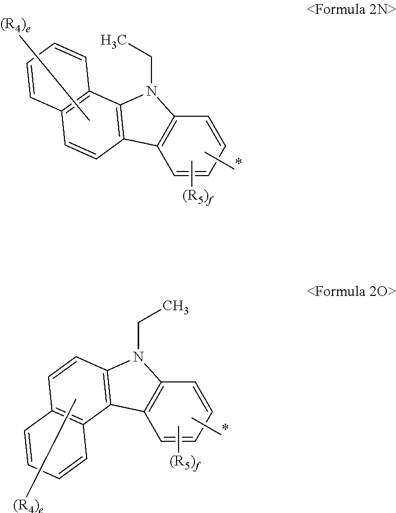
- benzocarbazole structure represented by one of Formulas 2A through 2C may have a benzocarbazole structure represented by one of Formulas 2D through 2O:
- R 4 and R 5 are the same as defined in the specification, e is one of fixed numbers from 1 to 6, and f is one of fixed numbers from 1 to 3.
- R 1 and R 2 are each independently one selected from the group consisting of a substituted or unsubstituted methyl group, a substituted or unsubstituted ethyl group, a substituted or unsubstituted propyl group, a substituted or unsubstituted butyl group, a substituted or unsubstituted pentyl group, a substituted or unsubstituted phenyl group, a substituted or unsubstituted naphthyl group, a substituted or unsubstituted fluorenyl group, a substituted or unsubstituted spiro-fluorenyl group, a substituted or unsubstituted anthryl group, a substituted or unsubstituted pyrazolyl group, a substituted or unsubstituted pyridinyl group, a substituted or unsubstituted pyrazinyl group, a substituted or un
- benzofluorene structure represented by one of Formulas 4A through 4C may have a benzofluorene structure represented by one of Formulas 4D through 4I below:
- the condensed-cyclic compound represented by Formula 1 above may be represented by one of Formulas 5A through 5I below:
- Ar 1 and Ar 2 are each independently one selected from the group consisting of a hydrogen atom, deuterium, a halogen atom, a hydroxyl group, a cyano group, an amino group, a nitro group, a carboxyl group, a substituted or unsubstituted methyl group, a substituted or unsubstituted ethyl group, a substituted or unsubstituted propyl group, a substituted or unsubstituted butyl group, a substituted or unsubstituted pentyl group, a substituted or unsubstituted phenyl group, a substituted or unsubstituted naphthyl group, a substituted or unsubstituted fluorenyl group, a substituted or unsubstituted spiro-fluorenyl group, a substituted or unsubstituted anthryl group, a substituted or unsubstituted pyr
- L 1 , L 2 , and L 3 are each independently one selected from the group consisting of a substituted or unsubstituted phenylene group, a substituted or unsubstituted pentalenylene group, a substituted or unsubstituted indenylene group, a substituted or unsubstituted naphthylene group, a substituted or unsubstituted azulenylene group, a substituted or unsubstituted heptalenylene group, a substituted or unsubstituted indacenylene group, a substituted or unsubstituted acenaphtylene group, a substituted or unsubstituted fluorenylene group, a substituted or unsubstituted spiro-fluorenyl group, a substituted or unsubstituted phenalenylene group, a substituted or unsubstituted
- a, b, and c may be each independently 0 or 1.
- a, b, and c are 0, a single bond is indicated.
- a, b, and c may be all 0.
- Ar 1 and Ar 2 may be each independently one selected from the group consisting of a hydrogen atom, deuterium, a halogen atom, a hydroxyl group, a cyano group, a nitro group, a carboxyl group, a substituted or unsubstituted methyl group, a substituted or unsubstituted ethyl group, a substituted or unsubstituted propyl group, a substituted or unsubstituted butyl group, a substituted or unsubstituted phenyl group, a substituted or unsubstituted pentalenyl group, a substituted or unsubstituted indenyl group, a substituted or unsubstituted naphthyl group, a substituted or unsubstituted azulenyl group, a substituted or unsubstituted heptalenyl group, a substituted or unsubstituted
- Ar 1 is disposed at the end in Formula 1 and may be for example, one selected from the group consisting of a substituted or unsubstituted phenyl group, a substituted or unsubstituted naphthyl group, a substituted or unsubstituted fluorenyl group, a substituted or unsubstituted spiro-fluorenyl group, a substituted or unsubstituted anthryl group, a substituted or unsubstituted pyrazolyl group, a substituted or unsubstituted pyridinyl group, a substituted or unsubstituted pyrazinyl group, a substituted or unsubstituted pyrimidinyl group, and a substituted or unsubstituted pyridazinyl group.
- R 1 , R 2 , R 3 , R 4 , R 5 , and R 6 may be each independently one selected from the group consisting of a hydrogen atom, deuterium, a halogen atom, a hydroxyl group, a cyano group, an amino group, a nitro group, a carboxyl group, a substituted or unsubstituted methyl group, a substituted or unsubstituted ethyl group, a substituted or unsubstituted propyl group, a substituted or unsubstituted butyl group, a substituted or unsubstituted pentyl group, a substituted or unsubstituted phenyl group, a substituted or unsubstituted pentalenyl group, a substituted or unsubstituted indenyl group, a substituted or unsubstituted naphthyl group, a substituted or
- R 1 and R 2 may be each independently one selected from the group consisting of a substituted or unsubstituted methyl group, a substituted or unsubstituted ethyl group, a substituted or unsubstituted propyl group, a substituted or unsubstituted butyl group, a substituted or unsubstituted pentyl group, a substituted or unsubstituted phenyl group, a substituted or unsubstituted naphthyl group, a substituted or unsubstituted fluorenyl group, a substituted or unsubstituted spiro-fluorenyl group, a substituted or unsubstituted anthryl group, a substituted or unsubstituted pyrazolyl group, a substituted or unsubstituted pyridinyl group, a substituted or unsubstituted pyrazinyl group, a substituted or or
- Formula 1 above may represent the condensed-cyclic compound, in which R 3 , R 4 , R 5 , and R 6 may each be a hydrogen atom and R 1 and R 2 may each be one selected from the group consisting of a substituted or unsubstituted methyl group, a substituted or unsubstituted ethyl group, a substituted or unsubstituted propyl group, a substituted or unsubstituted butyl group, a substituted or unsubstituted pentyl group, a substituted or unsubstituted phenyl group, a substituted or unsubstituted naphthyl group, a substituted or unsubstituted fluorenyl group, a substituted or unsubstituted spiro-fluorenyl group, a substituted or unsubstituted anthryl group, a substituted or unsubstituted pyrazolyl group, a substituted or un
- the condensed-cyclic compound represented by Formula 1 above may be, but is not limited to, one of compounds represented by Compounds 1 through 15 below:
- substituted A denotes “A, in which at least one hydrogen atom of A is substituted with one substituent selected from the group consisting of deuterium, a halogen atom, a hydroxyl group, a cyano group, a nitro group, a carboxyl group or a salt derivative thereof, a sulfonic acid group or a salt derivative thereof, a phosphate group or a salt derivative thereof, a C 1 -C 30 alkyl group, a alkenyl group, a C 2 -C 30 alkynyl group, a C 1 -C 30 alkoxy group, a C 3 -C 30 cycloalkyl group, a C 3 -C 30 cycloalkenyl group, a C 5 -C 30 aryl group, a C 5 -C 30 aryloxy group, a C 5 -C 30 aryloxy group, a C 5 -C 30 aryloxy group, a C 5 -C 30 ary
- the substituted A may denote “A, in which at least one hydrogen atom is substituted with deuterium, a halogen atom, a hydroxyl group, a cyano group, a nitro group, a carboxyl group, a methyl group, an ethyl group, a propyl group, a butyl group, a phenyl group, a pentalenyl group, an indenyl group, a naphthyl group, an azulenyl group, a heptalenyl group, an indacenyl group, an acenaphtyl group, a fluorenyl group, a spiro-fluorenyl group, a phenalenyl group, a phenanthrenyl group, an anthryl group, a fluoranthenyl group, a triphenylenyl group, a pyrenyl group, a chrysen
- the substituted C 1 -C 30 alkyl group denotes a saturated hydrocarbon group having a linear and branched structure in which one hydrogen atom is lacking alkane.
- Examples of the unsubstituted C 1 -C 30 alkyl group may include methyl, ethyl, propyl, isobutyl, sec-butyl, pentyl, iso-amyl, hexyl, and the like.
- a substituent of the substituted C 1 -C 30 alkyl group is described in the description for the “substituted A.”
- the unsubstituted C 2 -C 30 alkenyl group denotes a terminal group containing at least one carbon double bond at the middle or the end of the unsubstituted C 2 -C 30 alkyl group.
- Examples of the unsubstituted C 2 -C 30 alkenyl group may include ethenyl, prophenyl, butenyl, pentanyl, hexenyl, heptenyl, octenyl, propadienyl, isoprenyl, allyl, and the like.
- a substituent of the substituted C 2 -C 30 alkenyl group is described in the description for the “substituted A.”
- the unsubstituted C 2 -C 30 alkynyl group denotes a terminal group containing at least one carbon triple bond at the middle or the end of the unsubstituted C 2 -C 60 alkyl group.
- Examples of the unsubstituted C 2 -C 30 alkynyl group may include acetylenyl.
- a substituent of the substituted C 2 -C 30 alkynyl group is described in the description for the “substituted A.”
- the unsubstituted C 1 -C 30 alkoxy group has Formula of —OY (Y is the unsubstituted C 1 -C 30 alkyl group) and may be, for example, methoxy, ethoxy, isopropyloxy, butoxy, pentoxy, and the like.
- a substituent of the substituted C 1 -C 30 alkoxy group is described in the description for the “substituted A.”
- the unsubstituted C 3 -C 30 cycloalkyl group denotes a ring-type saturated hydrocarbon group and may be, for example, cyclopropyl, cyclobutyl, cyclopentyl, cyclohexyl, cyclooctyl, and the like.
- a substituent of the substituted C 3 -C 30 cycloalkyl group is described in the description for the “substituted A.”
- the unsubstituted C 3 -C 30 cycloalkenyl group denotes a ring-type unsaturated hydrocarbon group which has at least one carbon double bond and is not an aromatic ring.
- Examples of the unsubstituted C 3 -C 30 cycloalkenyl group may include cyclopropenyl, cyclobutenyl, cyclopentenyl, cyclohexenyl, cycloheptenyl, a 1,3-cyclohexadienyl group, a 1,4-cyclohexadienyl group, a 2,4-cycloheptadienyl group, a 1,5-cyclooctadienyl group, and the like.
- a substituent of the substituted C 3 -C 60 cycloalkenyl group is described in the description for the “substituted A.”
- the unsubstituted C 5 -C 30 aryl group denotes a monovalent group having a C 5 -C 30 carbocyclic aromatic system, wherein the monovalent group may be a monocyclic or polycyclic group. In the polycyclic group, at least two rings included therein may be fused to each other.
- Examples of the unsubstituted C 5 -C 30 aryl group may include phenyl, pentalenyl, indenyl, naphtyl, azulenyl, heptalenyl, indacenyl, acenaphtyl, fluorenyl, spiro-fluorenyl, phenalenyl, phenanthrenyl, anthryl, fluoranthenyl, triphenylenyl, pyrenyl, chrysenyl, naphthacenyl, picenyl, perylenyl, pentaphenyl, hexacenyl, and the like.
- a substituent of the substituted C 5 -C 30 aryl group is described in the description for the “substituted A.”
- the unsubstituted C 5 -C 30 aryloxy group denotes a monovalent group, to which carbon atoms of the C 5 -C 30 aryl group are attached through an oxygen linking group (—O—).
- a substituent of the substituted C 5 -C 30 aryloxy group is described in the description for the “substituted A.”
- the unsubstituted C 5 -C 30 arylthio group denotes a monovalent group, to which carbon atoms of the C 5 -C 30 aryl group are attached through a sulfur linking group (—S—).
- Examples of the unsubstituted C 5 -C 30 arylthio group may include phenylthio, naphtylthio, indanylthio, and indenylthio.
- a substituent of the substituted C 5 -C 30 arylthio group is described in the description for the “substituted A.”
- the unsubstituted C 2 -C 30 heterocyclic group denotes a monocyclic or polycyclic group including at least one ring containing at least one heteroatom selected from the group consisting of N, O, P, and S. In the polycyclic group, at least two rings included therein may be fused to each other.
- Examples of the unsubstituted C 2 -C 30 heterocyclic group may include pyrrolyl, imidazolyl, pyrazolyl, pyridinyl, pyrazinyl, pyrimidinyl, pyridazinyl, isoindolyl, indolyl, indazolyl, purinyl, quinolinyl, benzoquinolinyl, phthalazinyl, naphthyridinyl, quinoxalinyl, quinazolinyl, cinnolinyl, carbazolyl, phenanthridinyl, acridinyl, phenanthrolinyl, phenazinyl, benzooxazolyl, benzoimidazolyl, furanyl, benzofuranyl, thiophenyl, benzothiophenyl, thiazolyl, isothiazolyl, benzothiazolyl, isoxazolyl, o
- the unsubstituted C 1 -C 30 alkylene group denotes a divalent group having a linear and chain structure, in which two hydrogen atoms are lacking alkane. Examples of the unsubstituted C 1 -C 30 alkylene group may be understood with reference to the examples of the unsubstituted C 1 -C 30 alkyl group. A substituent of the substituted C 1 -C 30 alkylene group is described in the description for the “substituted A.”
- the unsubstituted C 5 -C 30 arylene group may denote a divalent group having a C 5 -C 30 carbocyclic aromatic system, wherein the divalent group may be a monocyclic or polycyclic group.
- Examples of the unsubstituted C 5 -C 30 arylene group may be understood with reference to the examples of the unsubstituted C 5 -C 30 aryl group.
- a substituent of the substituted C 5 -C 30 arylene group is described in the description for the “substituted A.”
- the unsubstituted divalent C 2 -C 30 heterocyclic group denotes a monocyclic or a polycyclic divalent group including at least one ring containing at least one heteroatom selected from the group consisting of N, O, P, and S and may be a monocyclic or a polycyclic group.
- Examples of the unsubstituted divalent C 2 -C 30 heterocyclic group may be understood with reference to the examples of the unsubstituted C 2 -C 30 heterocyclic group.
- a substituent of the substituted divalent C 2 -C 30 heterocyclic group is described in the description for the “substituted A.”
- the condensed-cyclic compound represented by Formula 1 may be synthesized by using a well-known organic synthesis method.
- the synthesis method of the condensed-cyclic compound may be easily recognized by one of ordinary skill in the art with reference to Examples which will be described later.
- an organic light-emitting device includes a first electrode, a second electrode facing the first electrode, and at least one organic layer interposed between the first electrode and the second electrode, wherein the at least one organic layer includes the condensed-cyclic compound represented by Formula 1.
- the condensed-cyclic compound represented by Formula 1 may be used in an organic light-emitting device.
- the condensed-cyclic compound represented by Formula 1 may excellently represent all colors such as red, green, blue, and white in an organic light-emitting device, lowers a driving voltage, increases efficiency of the organic light-emitting device, and improves the lifetime of organic light-emitting device.
- the organic layer may be a hole injection layer or a hole transport layer in the organic light-emitting device.
- the condensed-cyclic compound represented by Formula 1 may be included as a material for forming a hole injection layer or a hole transport layer.
- the organic layer may be a functional layer having functions of both hole injection and hole transport.
- the condensed-cyclic compound represented by Formula 1 may be included as a material for forming such a single layer.
- the organic light-emitting device may include a hole transport layer including the condensed-cyclic compound represented by Formula 1 or an emission layer including a fluorescent or phosphorescent host.
- the organic light-emitting device may have a structure including a first electrode/a hole injection layer/a hole transport layer including the condensed-cyclic compound represented by Formula 1/an emission layer/an electron transport layer/an electron injection layer/a second electrode.
- the present invention is not limited thereto.
- the organic layer may be an emission layer in an organic light-emitting device and thus the condensed-cyclic compound represented by Formula 1 may be included as a material for forming the emission layer. More specifically, the emission layer may only include the condensed-cyclic compound represented by Formula 1 or may further include another compound in addition to the condensed-cyclic compound represented by Formula 1.
- the condensed-cyclic compound represented by Formula 1 may be used as a fluorescent host or a phosphorescent host in the emission layer.
- the emission layer may further include a fluorescent dopant or a phosphorescent dopant. That is, the emission layer may include the condensed-cyclic compound represented by Formula 1 functioning as a fluorescent host and a fluorescent dopant or may include the condensed-cyclic compound represented by Formula 1 functioning as a phosphorescent host and a phosphorescent dopant.
- the condensed-cyclic compound represented by Formula 1 may be used as a fluorescent dopant of the emission layer.
- the condensed-cyclic compound represented by Formula 1 may further include a fluorescent host or a phosphorescent host. That is, the emission layer may include the condensed-cyclic compound represented by Formula 1 functioning as a fluorescent dopant, a phosphorescent host, or a fluorescent host.
- the organic light-emitting device may include at least one selected from the group consisting of a hole injection layer, a hole transport layer, an electron blocking layer, a hole blocking layer, an electron transport layer, and an electron injection layer between the first electrode and the second electrode, in addition to the emission layer.
- the at least one layer interposed between the first electrode and the second electrode may be formed by deposition or a wet process.
- at least one selected from the group consisting of a hole injection layer, a hole transport layer, an emission layer, a hole blocking layer, an electron transport layer, and an electron injection layer between the first electrode and the second electrode may be formed by deposition or a wet process.
- wet process is a process for providing a mixture obtained by mixing a predetermined material and a predetermined solvent to a predetermined substrate, drying and/or thermal treating the predetermined substrate so as to remove at least part of the predetermined solvent, and thereby forming a film including the predetermined material on the substrate.
- An organic layer including the condensed-cyclic compound represented by Formula 1 may be formed by a general vacuum deposition of a wet process.
- the condensed-cyclic compound represented by Formula 1 and the mixture including the solvent are provided to a hole transport layer region by using spin ti coating, spraying, inkjet printing, dipping, casting, gravure coating, bar coating, roll coating, wirebar coating, screen coating, flexo coating, offset coating, or laser transferring and then the mixture provided to the hole transport layer region is dried and/or heat treated so as to remove at least part of the solvent.
- the hole transport layer including the condensed-cyclic compound represented by Formula 1 may be formed.
- a layer including the condensed-cyclic compound represented by Formula 1 may be formed on the base film by using a wet process and the layer may be transferred on the hole transport layer region by laser transferring using laser.
- FIG. 1 is a cross-sectional view of an organic light-emitting device 10 according to an embodiment of the present invention.
- a structure and a manufacturing method of the organic light-emitting device 10 will be described with reference to FIG. 1 .
- the organic light-emitting device 10 includes a substrate 11 , a first electrode 12 , a hole injection layer 13 , a hole transport layer 14 , an emission layer 15 , an electron transport layer 16 , an electron injection layer 17 , and a second layer 18 sequentially in this order.
- the substrate 11 may be a substrate used in a general organic light-emitting device and may be, for example, a glass substrate or a transport plastic substrate having excellent mechanical strength, thermal stability, transparency, surface smoothness, easy-handling, and waterproofness.
- the first electrode 12 may be formed by providing a first electrode material on the substrate 11 using deposition or sputtering.
- the first electrode material may be selected from materials having a high work function so as to facilitate hole injection.
- the first electrode 12 may be a reflective electrode or a transmissive electrode. Examples of the first electrode material may include indium-tin oxide (ITO), Indium-zinc-oxide (IZO), tin oxide (SnO2), and zinc oxide (ZnO).
- the first electrode 12 may be formed as a reflective electrode.
- the first electrode 12 may include two different materials.
- the structure of the first electrode 12 may vary and, for example, the first electrode 12 may be formed to have a two-layered structure including two different materials.
- the hole injection layer 13 is formed on the first electrode 12 .
- the hole injection layer 13 may be formed on the first electrode 12 by using various methods such as vacuum deposition, a wet process, or laser transferring.
- the deposition condition may vary according to a compound used as a material for a hole injection layer, a structure of a desired hole injection layer, and thermal characteristics.
- the deposition condition may be, but is not limited to, deposition temperature of about 100 to about 500° C., a degree of vacuum of about 10 ⁇ 8 to about 10 ⁇ 3 torr, and deposition speed of about 0.01 to about 100 ⁇ /sec.
- the coating condition may vary according to a compound used as a material for a hole injection layer, a structure of a desired hole injection layer, and thermal characteristics.
- the coating condition may be, but is not limited to, coating speed of about 2000 rpm to about 5000 rpm and heat treatment temperature for removing a solvent after coating of about 80 to about 200° C.
- the condensed-cyclic compound may be used as the material for a hole injection layer.
- the material for a hole injection layer may include at least one selected from the group consisting of the condensed-cyclic compound and a well-known material for a hole injection layer and may include, for example, a phthalocyanine compound such as copper phthalocyanine, m-MTDATA (refer to Formula below), TDATA (refer to Formula below), 2-TDATA (refer to Formula below), Polyaniline/Dodecylbenzenesulfonic acid (Pani/DBSA), Poly(3,4-ethylenedioxythiophene)/Poly(4-styrenesulfonate) (PEDOT/PSS), Polyaniline/Camphor sulfonicacid (Pani/CSA), or Polyaniline/Poly(4-styrenesulfonate) (PAN1/PSS).
- a phthalocyanine compound such as copper phthalocyanine
- m-MTDATA (re
- a thickness of the hole injection layer 13 may be about 100 ⁇ to about 10000 ⁇ , for example, about 100 ⁇ to about 1000 ⁇ . When the thickness of the hole injection layer 13 is in the above range, satisfiable hole injection characteristics may be obtained without a substantial increase of a driving voltage.
- the hole transport layer 14 is formed on the hole injection layer 13 by using vacuum deposition, a wet process, and laser transferring.
- the deposition condition and coating condition may vary according to a used compound. However, in general, the conditions may be almost similar to the condition for forming the hole injection layer 13 .
- the condensed-cyclic compound represented by Formula 1 may be used as a material for a hole transport layer.
- the hole transport layer 14 may further include a well-known material for a hole transport layer, for example, TPD (refer to Formula below) and NPB (refer to Formula below).
- a thickness of the hole transport layer 14 may be about 50 ⁇ to about 1000 ⁇ , for example, about 100 ⁇ to about 800 ⁇ . When the thickness of the hole transport layer 14 is in the above range, satisfiable hole transport characteristics may be obtained without a substantial increase of a driving voltage.
- a function layer (not illustrated) simultaneously having a hole injection function and a hole transport function may be formed.
- a material for forming the function layer simultaneously having a hole injection function and a hole transport function may be selected from well-known materials.
- At least one selected from the group consisting of the hole injection layer 13 , the hole transport layer 14 , and the functional layer simultaneously having a hole injection function and a hole transport function may further include a charge-generation material for improving conductivity of a layer, in addition to the condensed-cyclic compound represented by Formula 1, a well-known hole injection material, and a well-known hole transport material.
- Examples of the charge-generation material may include a p-dopant.
- Examples of the p-dopant may include, but are not limited to, a quinone derivative such as tetracyanoquinonedimethan (TCNQ) or 2,3,5,6-tetrafluoro-tetracyano-1,4-benzonquinonedimethane (F4TCNQ); a metal oxide such as a tungsten oxide or a molybdenum oxide; and a cyano group containing a compound such as hexanitrile hexaazatriphenylene.
- TCNQ tetracyanoquinonedimethan
- F4TCNQ 2,3,5,6-tetrafluoro-tetracyano-1,4-benzonquinonedimethane
- F4TCNQ 2,3,5,6-tetrafluoro-tetracyano-1,4-benzonquinonedimethane
- metal oxide such as a
- the charge-generation material is homogeneously or non-homogeneously dispersed in the layers.
- the emission layer 15 may be formed on the hole transport layer 14 or the functional layer simultaneously having a hole injection function and a hole transport function by using vacuum deposition, a wet process, or laser transferring.
- the deposition condition may vary according to a used compound. However, in general, the conditions may be almost similar to the condition for forming the hole injection layer 13 .
- the emission layer 15 may include at least one selected from the group consisting of the condensed-cyclic compound of Formula 1 and well-known phosphorescent host, fluorescent host, phosphorescent dopant, and fluorescent dopant.
- the condensed-cyclic compound may function as a phosphorescent host, a fluorescent host, a phosphorescent dopant, or a fluorescent dopant.
- Examples of the well-known host may include 4,4′-N,N′-dicarbazole-biphenyl (CBP), 9,10-di-naphthalene-2-yl-anthracene (AND, refer to Formula below), TPBI (refer to Formula below), TBADN (refer to Formula below), E3 (refer to Formula below).
- CBP 4,4′-N,N′-dicarbazole-biphenyl
- AND 9,10-di-naphthalene-2-yl-anthracene
- TPBI 910-di-naphthalene-2-yl-anthracene
- TPBI 910-di-naphthalene-2-yl-anthracene
- TPBI 910-di-naphthalene-2-yl-anthracene
- TPBI 9,10-di-naphthalene-2-yl-anthracene
- TBADN 9-di-naphthal
- At least one of the fluorescent dopant and the phosphorescent dopant may be used as a dopant.
- the phosphorescent dopant may be an organic metal complex including Ir, Pt, Os, Re, Ti, Zr, Hf, or combinations including at least two of Ir, Pt, Os, Re, Ti, Zr, and Hf.
- the present invention is not limited thereto.
- PtOEP (refer to Formula below), Ir (piq) 3 (refer to Formula below), or Btp 2 Ir(acac) (refer to Formula below) may be used.
- Ir (piq) 3 (refer to Formula below)
- Btp 2 Ir(acac) (refer to Formula below)
- the present invention is not limited thereto.
- the present invention is not limited thereto.
- F 2 Irpic (refer to Formula below), (F 2 ppy) 2 Ir(tmd) (refer to Formula below), Ir(dfppz) 3 (refer to Formula below), DPVBi (refer to Formula below), 4,4′-bis(4-diphenylaminosteril) biphenyl (DPAVBi, refer to Formula below), or 2,5,8,11-tetra-tert-butylpherylene (TBPe, refer to Formula below) may be used.
- DPAVBi 4,4′-bis(4-diphenylaminosteril) biphenyl
- TBPe 2,5,8,11-tetra-tert-butylpherylene
- an amount of the dopant may be generally in the range of about 0.01 to about 15 parts by weight based on 100 parts by weight of the host.
- the present invention is not limited thereto.
- a thickness of the emission layer 15 may be about 100 ⁇ to about 1000 ⁇ , for example, about 200 ⁇ to about 600 ⁇ . When the thickness of the emission layer 15 is in the above range, excellent emission characteristic may appear without a substantial increase of a driving voltage.
- a hole blocking layer (not illustrated) may be formed between the emission layer 15 and the hole transport layer 16 by using vacuum deposition, a wet process, or laser transferring so as to prevent triplet excitons or holes from being diffused to the electron transport layer 16 .
- the conditions thereof may vary according to a used compound. However, in general, the conditions may be almost similar to the condition for forming the hole injection layer 13 .
- a well-known hole blocking material may be used. Examples of the well-known hole blocking material may include an oxadiazole deriative, a triazole derivative, and a phenanthroline derivative.
- a thickness of the hole blocking layer may be about 50 ⁇ to about 1000 ⁇ , for example, about 100 ⁇ to about 300 ⁇ . When the thickness of the hole blocking layer is in the above range, excellent hole blocking characteristic may appear without a substantial increase of a driving voltage.
- the electron transport layer 16 is formed by using vacuum deposition, a wet process, or laser transferring.
- the conditions thereof may vary according to a used compound. However, in general, the conditions may be almost similar to the condition for forming the hole injection layer 13 .
- a material for forming the electron transport layer 16 is used to stably transport electrons injected from a cathode and may include a well-known transport material.
- Examples of the well-known transport material may include a quinoline derivative, in particular, tris(8-quinolinolate)aluminum (Alq 3 ), TAZ (refer to Formula below), Balq (refer to Formula below), beryllium bis benzoquinolin-10-olate (Bebq 2 ).
- a quinoline derivative in particular, tris(8-quinolinolate)aluminum (Alq 3 ), TAZ (refer to Formula below), Balq (refer to Formula below), beryllium bis benzoquinolin-10-olate (Bebq 2 ).
- Alq 3 tris(8-quinolinolate)aluminum
- TAZ (refer to Formula below)
- Balq (refer to Formula below)
- Bebq 2 beryllium bis benzoquinolin-10-olate
- the present invention is not limited thereto.
- a thickness of the electron transport layer 16 may be about 100 ⁇ to about 1000 ⁇ , for example, about 150 ⁇ to about 500 ⁇ . When the thickness of the electron transport layer 16 is in the above range, excellent electron transport characteristic may be obtained without a substantial increase of a driving voltage.
- the electron transport layer 16 may include an electron transport organic compound and a metal-containing material.
- the electron transport organic compound may include, but are not limited to, 9,10-di(naphthalene-2-yl)anthracene (AND); and an anthracene-based compound such as a compound 301 or 302 below:
- the metal-containing material may include a Li complex.
- Li complex may include, but are not limited to, lithium quinolate (LiQ) or compound 303 below:
- the electron injection layer 17 which facilitates electron injection from a cathode, may be formed on the electron transport layer 16 .
- a material for forming the electron injection layer 17 may include a well-known arbitrary material for forming the electron injection layer, such as LiF, NaCl, CsF, Li 2 O, or BaO.
- the deposition condition of the electron injection layer 17 may vary according a used compound. However, in general, the condition may be almost similar to the condition for forming the hole injection layer 13 .
- a thickness of the electron injection layer 17 may be about 1 ⁇ to about 100 ⁇ , for example, about 3 ⁇ to about 90 ⁇ . When the thickness of the electron injection layer 17 is in the above range, satisfiable hole injection characteristics may be obtained without a substantial increase of a driving voltage.
- the second electrode 18 as a transmissive electrode may be formed on the electron injection layer 17 .
- the second electrode 18 may be a cathode, which is an electrode injection electrode.
- a metal for forming the second electrode 18 may include a metal having low work function, an alloy, an electric conducting compound, and mixtures thereof.
- the transmissive electrode may be obtained by forming a thin film by using lithium (Li), magnesium (Mg), aluminum (Al), aluminum-lithium (Al—Li), calcium (Ca), magnesium-indium (Mg—In), or magnesium-silver (Mg—Ag).
- the transmissive electrode may be formed by using ITO or IZO.
- a flat panel display apparatus includes an organic light-emitting device including a transistor including a source electrode, a drain electrode, a gate, and an active layer, and an organic layer including the to condensed-cyclic compound represented by Formula 1 above, wherein in the organic light-emitting device, the first electrode is electrically connected to the source electrode or the drain electrode.
- the organic light-emitting device may be included in the flat panel display apparatus including the transistor.
- the active layer of the transistor may vary and may be, for example, an amorphous silicon layer, a crystallized silicon layer, an organic semiconductor layer, or an oxide semiconductor layer.
- reaction solution was cooled down to room temperature and was extracted three times using 40 ml of distilled water and diethyl ether. An organic layer is dried using anhydrous magnesium sulfate and a solvent was removed, thereby obtaining residue. The residue was separated and purified using silica gel column chromatography, thereby obtaining 2.08 g of intermediate (yield 62%).
- IDE215 (Idemitsu Co., Ltd.) as a blue fluorescent host
- IDE118 (Idemitsu Co., Ltd.) as a blue fluorescent dopant were simultaneously deposited on the hole transport layer by a weight ratio of 97:3, thereby forming an emission layer having a thickness of 2001.
- Aluminum tris(8-hydroxyquinoline) was vacuum deposited on the emission layer, thereby forming an electron transport layer having a thickness of 300 ⁇ .
- LiF was vacuum deposited on the electron transport layer so as to form an electron injection layer having a thickness of 10 ⁇ and then Al was vacuum deposited on the electron injection layer so as to form a cathode having a thickness of 3000 ⁇ . Therefore, an organic light-emitting device was completely manufactured.
- the organic light-emitting device had a current density of 100 mA/cm 2 , a driving voltage of 6.63 V, color coordinates of (0.143, 0.241), and emission efficiency of 7.11 cd/A.
- Intermediate C was synthesized in the same manner as in synthesis Example 1, except that intermediate C-1 was used instead of intermediate A-1.
- An organic light-emitting device was completely manufactured in the same manner as in Example 1, except that compound 2 was used instead of compound 1 when forming the hole transport layer.
- the organic light-emitting device had a current density of 100 mA/cm 2 , a driving voltage of 6.75 V, color coordinates of (0.143, 0.242), and emission efficiency of 7.34 cd/A.
- Intermediate D was synthesized in the same manner as in synthesis Example 1, except that intermediate D-1 was used instead of intermediate B-1.
- An organic light-emitting device was completely manufactured in the same manner as in Example 1, except that compound 3 was used instead of compound 1 when forming the hole transport layer.
- the organic light-emitting device had a current density of 100 mA/cm 2 , a driving voltage of 6.59 V, color coordinates of (0.143, 0.242), and emission efficiency of 7.21 cd/A.
- An organic light-emitting device was completely manufactured in the same manner as in Example 1, except that compound 4 was used instead of compound 1 when forming the hole transport layer.
- the organic light-emitting device had a current density of 100 mA/cm 2 , a driving voltage of 6.69 V, color coordinates of (0.143, 0.241), and emission efficiency of 7.09 cd/A.
- An organic light-emitting device was completely manufactured in the same manner as in Example 1, except that compound 5 was used instead of compound 1 when forming the hole transport layer.
- the organic light-emitting device had a current density of 100 mA/cm 2 , a driving voltage of 6.78 V, color coordinates of (0.144, 0.241), and emission efficiency of 7.28 cd/A.
- An organic light-emitting device was completely manufactured in the same manner as in Example 1, except that 4,4′-bis[N-4,4′-bis[N-(1-naphtyl)-N-phenylamino]biphenyl (NPB) was used instead of compound 1 when forming the hole transport layer.
- NPB 4,4′-bis[N-4,4′-bis[N-(1-naphtyl)-N-phenylamino]biphenyl
- the organic light-emitting device had a current density of 100 mA/cm 2 , a driving voltage of 7.82 V, color coordinates of (0.143, 0.242), and emission efficiency of 5.72 cd/A.
- Carbazole (16.7 g, 100 mmol), iodo benzene (26.5 g, 130 mmol), CuI (1.9 g, 10 mmol), K2CO3 (8 g 138 g, 1 mol), and 18-crown-6 (530 mg, 2 mmol) were dissolved in DMPU (1,3-Dimethyl-3,4,5,6-tetrahydro-(1H)-pyrimidinone) (500 mL) so as to form a reaction mixture. Then, the reaction mixture was heated for 8 hours at 170° C.
- reaction mixture was cooled down to room temperature, a solid material was filtered, a small amount of ammonia water was added to a filtrate, and was washed three times using diethyl ether (300 ml). The washed diethyl ether layer was dried using MgSO 4 and reduced in pressure to obtain a product. Then, the product was separated and purified using silica gel column chromatography, thereby obtaining 22 g (yield 90%) of intermediate E-1 as a white solid.
- An organic light-emitting device was completely manufactured in the same manner as in Example 1, except that compound 202 was used instead of compound 1 when forming the hole transport layer.
- the organic light-emitting device had a current density of 100 mA/cm 2 , a driving voltage of 6.71 V, color coordinates of (0.143, 0.241), and emission efficiency of 6.52 cd/A.
- An organic light-emitting device was completely manufactured in the same mariner as in Example 1, except that compound 203 was used instead of compound 1 when forming the hole transport layer.
- the organic light-emitting device had a current density of 100 mA/cm 2 , a driving voltage of 6.83 V, color coordinates of (0.143, 0.241), and emission efficiency of 6.85 cd/A.
- An organic light-emitting device was completely manufactured in the same manner as in Example 1, except that compound 204 was used instead of compound 1 when forming the hole transport layer.
- the organic light-emitting device had a current density of 100 mA/cm 2 , a driving voltage of 7.11 V, color coordinates of (0.144, 0.242), and emission efficiency of 5.93 cd/A.
- An organic light-emitting device was completely manufactured in the same manner as in Example 1, except that compound 205 was used instead of compound 1 when forming the hole transport layer.
- the organic light-emitting device had a current density of 100 mA/cm 2 , a driving voltage of 6.85 V, color coordinates of (0.143, 0.242), and emission efficiency of 6.64 cd/A.
- the organic light-emitting devices of Examples 1 through 5 and the organic light-emitting devices of Comparative Examples 1 through 5 were evaluated in terms of current density, driving voltage, efficiency, and half-luminance lifetime using PR650 (Spectroscan) Source Measurement Unit (PhotoResearch Co. LTD.). The results are shown in Table 1 below (half-luminance lifetime was measured at an applied current of 4 mA)
- emission efficiencies and half-luminance lifetimes of the organic light-emitting devices of Examples 1 through 5 are higher and longer than those of the organic light-emitting devices of Comparative Examples 1 through 5. Also, the driving voltages of the organic light-emitting devices of Examples 1, 3, and 4 are lower than those of the organic light-emitting devices of Comparative Examples 1 through 5. In this regard, the organic light-emitting devices of Examples 1 through 5 have excellent performance, for example, high emission efficiencies and long lifetime.
- the organic light-emitting device including the condensed-cyclic compound represented by Formula 1 has high emission efficiency and long lifetime and thus a flat panel display apparatus has excellent performance.
Abstract

-
- wherein, X, Y, A1, A2, L1, L2, L3, Ar1, R1, R2, R3, R4, R5, R6, a, b, c, d, e, f, and g are described in the detailed description of the invention. The organic light-emitting device including an organic layer including the compound above has low driving voltage, high emission efficiency, and long lifetime.
Description


is a structure, in which a bicyclic aromatic ring is fused into indoline or benzothiophene and A1 may be, for example, a fused bicyclic aromatic ring which may contain 8, 9, or 10 carbon atoms.

is a structure, in which a bicyclic aromatic ring is fused into indene and A2 may be, for example, a fused bicyclic aromatic ring which may contain 8, 9, or 10 carbon atoms.

may be a benzocarbazole derivative or a benzonaphtothiopene derivative and

may be a benzofluorene derivative. The condensed-cyclic compound represented by Formula 1 above may have various structures according to locations where the naphthalene ring or the indene ring is fused into indene, indoline, or benzothiophene.

may have a benzocarbazole structure represented by one of Formulas 2A through 2C below:


may be a benzonaphtothiopene structure represented by one of Formulas 3A through 3C below:


may be a benzofluorene structure represented by one of Formulas 4A through 4C below:


| TABLE 1 | ||||||
| Current | Half- | |||||
| Driving | density | Emission | luminance | |||
| Electron | voltage | (mA/ | Efficiency | lifetime | ||
| transport layer | (V) | cm2) | (cd/A) | (h) | ||
| Example 1 | Compound 1 | 6.63 | 100 | 7.11 | 362 |
| Example 2 | Compound 2 | 6.75 | 100 | 7.34 | 370 |
| Example 3 | Compound 3 | 6.59 | 100 | 7.21 | 334 |
| Example 4 | Compound 4 | 6.69 | 100 | 7.09 | 358 |
| Example 5 | Compound 5 | 6.78 | 100 | 7.28 | 348 |
| Comparative | NPB | 7.82 | 100 | 5.72 | 273 |
| Example 1 | |||||
| Comparative | Compound 202 | 6.71 | 100 | 6.52 | 226 |
| Example 2 | |||||
| Comparative | Compound 203 | 6.83 | 100 | 6.85 | 258 |
| Example 3 | |||||
| Comparative | Compound 204 | 7.11 | 100 | 5.93 | 183 |
| Example 4 | |||||
| Comparative | Compound 205 | 6.85 | 100 | 6.64 | 251 |
| Example 5 | |||||
Claims (20)


Applications Claiming Priority (2)
| Application Number | Priority Date | Filing Date | Title |
|---|---|---|---|
| KR1020110044076A KR101894023B1 (en) | 2011-05-11 | 2011-05-11 | Condensed-cyclic compound, organic light-emitting diode comprising the same, and flat display device |
| KR10-2011-0044076 | 2011-05-11 |
Publications (2)
| Publication Number | Publication Date |
|---|---|
| US20120286247A1 US20120286247A1 (en) | 2012-11-15 |
| US8808880B2 true US8808880B2 (en) | 2014-08-19 |
Family
ID=47141283
Family Applications (1)
| Application Number | Title | Priority Date | Filing Date |
|---|---|---|---|
| US13/243,959 Active 2033-02-07 US8808880B2 (en) | 2011-05-11 | 2011-09-23 | Condensed-cyclic compound, organic light-emitting device comprising the same, and flat panel display apparatus |
Country Status (2)
| Country | Link |
|---|---|
| US (1) | US8808880B2 (en) |
| KR (1) | KR101894023B1 (en) |
Cited By (3)
| Publication number | Priority date | Publication date | Assignee | Title |
|---|---|---|---|---|
| US6291156B1 (en) | 1997-04-03 | 2001-09-18 | Syngenta Participations Ag | Plant pest control |
| US20180026201A1 (en) * | 2015-01-05 | 2018-01-25 | Board Of Supervisors Of Louisiana State University And Agricultural And Mechanical College | Carbazole-based gumbos for highly efficient blue oleds |
| US10882821B1 (en) | 2017-09-26 | 2021-01-05 | The Board Of Trustees Of The Leland Stanford Junior University | Enantiomeric compound for the reduction of the deleterious activity of extended nucleotide repeat containing genes |
Families Citing this family (14)
| Publication number | Priority date | Publication date | Assignee | Title |
|---|---|---|---|---|
| KR101561332B1 (en) * | 2012-12-10 | 2015-10-26 | 주식회사 두산 | New organic compounds and organic electro luminescence device comprising the same |
| KR102055685B1 (en) * | 2012-12-27 | 2019-12-16 | 삼성디스플레이 주식회사 | Organic light emitting diode comprising the same |
| JP6367229B2 (en) * | 2013-01-03 | 2018-08-01 | メルク パテント ゲーエムベーハー | Compounds for electronic devices |
| KR102162793B1 (en) * | 2013-03-05 | 2020-10-08 | 삼성디스플레이 주식회사 | Compound and organic light emitting device comprising the same |
| CN113501778A (en) * | 2013-10-25 | 2021-10-15 | 株式会社Lg化学 | Blue light-emitting compound |
| KR101939552B1 (en) * | 2013-12-06 | 2019-01-17 | 롬엔드하스전자재료코리아유한회사 | Organic Electroluminescent Compound and Organic Electroluminescent Device Comprising the Same |
| CN107074763B (en) * | 2014-10-20 | 2021-01-05 | 株式会社Lg化学 | Blue light-emitting compound |
| CN104672126B (en) * | 2014-12-31 | 2017-07-18 | 固安鼎材科技有限公司 | A kind of benzo naphtho- five-ring heterocycles derivative and its application |
| KR102611417B1 (en) * | 2016-01-25 | 2023-12-07 | 덕산네오룩스 주식회사 | Compound for organic electronic element, organic electronic element using the same, and an electronic device thereof |
| KR20170124957A (en) * | 2016-05-03 | 2017-11-13 | 롬엔드하스전자재료코리아유한회사 | Organic electroluminescent compound and organic electroluminescent device comprising the same |
| CN107652287B (en) * | 2017-11-01 | 2019-07-23 | 烟台九目化学制品有限公司 | A kind of miscellaneous carbazole compound of the miscellaneous fluorenes-benzo of benzo and application |
| KR102237174B1 (en) * | 2018-05-23 | 2021-04-07 | 주식회사 엘지화학 | Polycyclic compound and organic light emitting device comprising the same |
| KR102192497B1 (en) * | 2019-10-21 | 2020-12-17 | 롬엔드하스전자재료코리아유한회사 | Organic Electroluminescent Compound and Organic Electroluminescent Device Comprising the Same |
| KR102321559B1 (en) * | 2019-10-21 | 2021-11-05 | 롬엔드하스전자재료코리아유한회사 | Organic Electroluminescent Compound and Organic Electroluminescent Device Comprising the Same |
Citations (10)
| Publication number | Priority date | Publication date | Assignee | Title |
|---|---|---|---|---|
| US20040106514A1 (en) * | 2002-12-03 | 2004-06-03 | Sandor Nagy | Bimetallic indenoindolyl catalysts |
| KR20050097670A (en) | 2004-04-02 | 2005-10-10 | 삼성에스디아이 주식회사 | Fluorene-based compound and organic electroluminescent display device using the same |
| KR20060005755A (en) | 2004-07-14 | 2006-01-18 | 삼성에스디아이 주식회사 | Phenylcarbazole compounds and organic electroluminescence devices using the same |
| US20070231503A1 (en) | 2004-04-02 | 2007-10-04 | Hwang Seok-Hwan | Organic light emitting device and flat panel display device comprising the same |
| KR20070114669A (en) | 2007-07-30 | 2007-12-04 | 삼성에스디아이 주식회사 | An organic light emitting device and a flat panel display device comprising the same |
| KR20070114562A (en) | 2006-05-29 | 2007-12-04 | 삼성에스디아이 주식회사 | An organic light emitting device and a flat panel display device comprising the same |
| KR20080031808A (en) | 2006-10-05 | 2008-04-11 | 짓쏘 가부시끼가이샤 | Benzofluorene compound, emission materials and organic electroluminescent device |
| US20080107919A1 (en) | 2004-11-29 | 2008-05-08 | Seok-Hwan Hwang | Phenylcarbazole-based compound and organic electroluminescent device employing the same |
| JP2008285561A (en) | 2007-05-16 | 2008-11-27 | Tosoh Corp | Organic electroluminescence material and organic electroluminescent element using the same |
| WO2010110553A2 (en) * | 2009-03-23 | 2010-09-30 | Dow Advanced Display Materials, Ltd. | Novel organic electroluminescent compounds and organic electroluminescent device using the same |
Family Cites Families (1)
| Publication number | Priority date | Publication date | Assignee | Title |
|---|---|---|---|---|
| JP5446247B2 (en) * | 2008-12-24 | 2014-03-19 | 東ソー株式会社 | Amine derivatives and uses thereof |
-
2011
- 2011-05-11 KR KR1020110044076A patent/KR101894023B1/en active IP Right Grant
- 2011-09-23 US US13/243,959 patent/US8808880B2/en active Active
Patent Citations (11)
| Publication number | Priority date | Publication date | Assignee | Title |
|---|---|---|---|---|
| US20040106514A1 (en) * | 2002-12-03 | 2004-06-03 | Sandor Nagy | Bimetallic indenoindolyl catalysts |
| KR20050097670A (en) | 2004-04-02 | 2005-10-10 | 삼성에스디아이 주식회사 | Fluorene-based compound and organic electroluminescent display device using the same |
| US20070231503A1 (en) | 2004-04-02 | 2007-10-04 | Hwang Seok-Hwan | Organic light emitting device and flat panel display device comprising the same |
| KR20060005755A (en) | 2004-07-14 | 2006-01-18 | 삼성에스디아이 주식회사 | Phenylcarbazole compounds and organic electroluminescence devices using the same |
| US20080107919A1 (en) | 2004-11-29 | 2008-05-08 | Seok-Hwan Hwang | Phenylcarbazole-based compound and organic electroluminescent device employing the same |
| KR20070114562A (en) | 2006-05-29 | 2007-12-04 | 삼성에스디아이 주식회사 | An organic light emitting device and a flat panel display device comprising the same |
| KR20080031808A (en) | 2006-10-05 | 2008-04-11 | 짓쏘 가부시끼가이샤 | Benzofluorene compound, emission materials and organic electroluminescent device |
| US20080160347A1 (en) | 2006-10-05 | 2008-07-03 | Guofang Wang | Benzofluorene compound, emission materials and organic electroluminescent device |
| JP2008285561A (en) | 2007-05-16 | 2008-11-27 | Tosoh Corp | Organic electroluminescence material and organic electroluminescent element using the same |
| KR20070114669A (en) | 2007-07-30 | 2007-12-04 | 삼성에스디아이 주식회사 | An organic light emitting device and a flat panel display device comprising the same |
| WO2010110553A2 (en) * | 2009-03-23 | 2010-09-30 | Dow Advanced Display Materials, Ltd. | Novel organic electroluminescent compounds and organic electroluminescent device using the same |
Cited By (4)
| Publication number | Priority date | Publication date | Assignee | Title |
|---|---|---|---|---|
| US6291156B1 (en) | 1997-04-03 | 2001-09-18 | Syngenta Participations Ag | Plant pest control |
| US20180026201A1 (en) * | 2015-01-05 | 2018-01-25 | Board Of Supervisors Of Louisiana State University And Agricultural And Mechanical College | Carbazole-based gumbos for highly efficient blue oleds |
| US10109802B2 (en) * | 2015-01-05 | 2018-10-23 | Board Of Supervisors Of Louisiana State University And Agricultural And Mechanical College | Carbazole-based gumbos for highly efficient blue OLEDs |
| US10882821B1 (en) | 2017-09-26 | 2021-01-05 | The Board Of Trustees Of The Leland Stanford Junior University | Enantiomeric compound for the reduction of the deleterious activity of extended nucleotide repeat containing genes |
Also Published As
| Publication number | Publication date |
|---|---|
| KR20120127550A (en) | 2012-11-22 |
| US20120286247A1 (en) | 2012-11-15 |
| KR101894023B1 (en) | 2018-10-05 |
Similar Documents
| Publication | Publication Date | Title |
|---|---|---|
| US8808880B2 (en) | Condensed-cyclic compound, organic light-emitting device comprising the same, and flat panel display apparatus | |
| US8999525B2 (en) | Condensed-cyclic compound, organic light-emitting device comprising the same, and flat panel display apparatus including the device | |
| US10665788B2 (en) | Amine-based compound, organic light-emitting diode including the same, and organic light-emitting apparatus including the amine-based compound | |
| US9238623B2 (en) | Condensed-cyclic compound and organic light-emitting diode including the same | |
| US9567287B2 (en) | Compound for organic light-emitting diode and organic light-emitting diode including the same | |
| US9515265B2 (en) | Organic light-emitting device | |
| US9309197B2 (en) | Heterocyclic compound, organic light-emitting diode comprising the heterocyclic compound, and flat panel display device comprising the organic light-emitting diode | |
| US9012042B2 (en) | Condensed-cyclic compound, organic light-emitting device comprising the same, and flat panel display apparatus | |
| US9224961B2 (en) | Condensed-cyclic compound, organic light-emitting diode comprising the same and flat panel display device comprising the organic light-emitting diode | |
| US20150255736A1 (en) | Compound and organic light-emitting device including the same | |
| US8597801B2 (en) | Heterocyclic compound, organic light-emitting device including the heterocyclic compound, and flat display device including the organic light-emitting device | |
| US8771844B2 (en) | Heterocyclic compound and organic light-emitting diode and flat display device including the heterocyclic compound | |
| US9455407B2 (en) | Compound and organic light-emitting device including the same | |
| US9653689B2 (en) | Condensed-cyclic compound and organic light-emitting diode including the same | |
| US9172050B2 (en) | Compound and organic light emitting device including the same | |
| US10038158B2 (en) | Organic light-emitting device | |
| US9276218B2 (en) | Arylamine compound and organic light-emitting device comprising same | |
| US9666809B2 (en) | Compound and organic light-emitting device including the same | |
| US9312497B2 (en) | Heterocyclic compound, organic light-emitting diode including the heterocyclic compound, and flat display device including the organic light-emitting diode | |
| US8623521B2 (en) | Heterocyclic compound and organic light-emitting diode and flat display device including the heterocyclic compound | |
| US9564603B2 (en) | Heterocyclic compound and organic light-emitting device including the same | |
| US8889270B2 (en) | Organic light-emitting device |
Legal Events
| Date | Code | Title | Description |
|---|---|---|---|
| AS | Assignment |
Owner name: SAMSUNG MOBILE DISPLAY CO., LTD., A CORPORATION CH Free format text: ASSIGNMENT OF ASSIGNORS INTEREST;ASSIGNORS:KIM, HEE-YEON;YANG, SEUNG-GAK;YI, JEOUNG-IN;AND OTHERS;REEL/FRAME:027392/0236 Effective date: 20110923 Owner name: SAMSUNG MOBILE DISPLAY CO., LTD., ACORPORATION CHA Free format text: ASSIGNMENT OF ASSIGNORS INTEREST;ASSIGNORS:KIM, HEE-YEON;YANG, SEUNG-GAK;YI, JEOUNG-IN;AND OTHERS;REEL/FRAME:027392/0236 Effective date: 20110923 |
|
| AS | Assignment |
Owner name: SAMSUNG DISPLAY CO., LTD., KOREA, REPUBLIC OF Free format text: MERGER;ASSIGNOR:SAMSUNG MOBILE DISPLAY CO., LTD.;REEL/FRAME:029241/0599 Effective date: 20120702 |
|
| FEPP | Fee payment procedure |
Free format text: PAYOR NUMBER ASSIGNED (ORIGINAL EVENT CODE: ASPN); ENTITY STATUS OF PATENT OWNER: LARGE ENTITY |
|
| STCF | Information on status: patent grant |
Free format text: PATENTED CASE |
|
| MAFP | Maintenance fee payment |
Free format text: PAYMENT OF MAINTENANCE FEE, 4TH YEAR, LARGE ENTITY (ORIGINAL EVENT CODE: M1551) Year of fee payment: 4 |
|
| MAFP | Maintenance fee payment |
Free format text: PAYMENT OF MAINTENANCE FEE, 8TH YEAR, LARGE ENTITY (ORIGINAL EVENT CODE: M1552); ENTITY STATUS OF PATENT OWNER: LARGE ENTITY Year of fee payment: 8 |