US8801991B2 - Heat-seal failure prevention method and article - Google Patents
Heat-seal failure prevention method and article Download PDFInfo
- Publication number
- US8801991B2 US8801991B2 US13/303,758 US201113303758A US8801991B2 US 8801991 B2 US8801991 B2 US 8801991B2 US 201113303758 A US201113303758 A US 201113303758A US 8801991 B2 US8801991 B2 US 8801991B2
- Authority
- US
- United States
- Prior art keywords
- layer
- polymeric material
- flow
- heat
- article
- Prior art date
- Legal status (The legal status is an assumption and is not a legal conclusion. Google has not performed a legal analysis and makes no representation as to the accuracy of the status listed.)
- Active, expires
Links
Images


Classifications
-
- B—PERFORMING OPERATIONS; TRANSPORTING
- B29—WORKING OF PLASTICS; WORKING OF SUBSTANCES IN A PLASTIC STATE IN GENERAL
- B29C—SHAPING OR JOINING OF PLASTICS; SHAPING OF MATERIAL IN A PLASTIC STATE, NOT OTHERWISE PROVIDED FOR; AFTER-TREATMENT OF THE SHAPED PRODUCTS, e.g. REPAIRING
- B29C45/00—Injection moulding, i.e. forcing the required volume of moulding material through a nozzle into a closed mould; Apparatus therefor
- B29C45/16—Making multilayered or multicoloured articles
-
- B—PERFORMING OPERATIONS; TRANSPORTING
- B29—WORKING OF PLASTICS; WORKING OF SUBSTANCES IN A PLASTIC STATE IN GENERAL
- B29C—SHAPING OR JOINING OF PLASTICS; SHAPING OF MATERIAL IN A PLASTIC STATE, NOT OTHERWISE PROVIDED FOR; AFTER-TREATMENT OF THE SHAPED PRODUCTS, e.g. REPAIRING
- B29C45/00—Injection moulding, i.e. forcing the required volume of moulding material through a nozzle into a closed mould; Apparatus therefor
- B29C45/0053—Injection moulding, i.e. forcing the required volume of moulding material through a nozzle into a closed mould; Apparatus therefor combined with a final operation, e.g. shaping
-
- B—PERFORMING OPERATIONS; TRANSPORTING
- B29—WORKING OF PLASTICS; WORKING OF SUBSTANCES IN A PLASTIC STATE IN GENERAL
- B29C—SHAPING OR JOINING OF PLASTICS; SHAPING OF MATERIAL IN A PLASTIC STATE, NOT OTHERWISE PROVIDED FOR; AFTER-TREATMENT OF THE SHAPED PRODUCTS, e.g. REPAIRING
- B29C45/00—Injection moulding, i.e. forcing the required volume of moulding material through a nozzle into a closed mould; Apparatus therefor
- B29C45/16—Making multilayered or multicoloured articles
- B29C45/1642—Making multilayered or multicoloured articles having a "sandwich" structure
-
- B—PERFORMING OPERATIONS; TRANSPORTING
- B29—WORKING OF PLASTICS; WORKING OF SUBSTANCES IN A PLASTIC STATE IN GENERAL
- B29C—SHAPING OR JOINING OF PLASTICS; SHAPING OF MATERIAL IN A PLASTIC STATE, NOT OTHERWISE PROVIDED FOR; AFTER-TREATMENT OF THE SHAPED PRODUCTS, e.g. REPAIRING
- B29C65/00—Joining or sealing of preformed parts, e.g. welding of plastics materials; Apparatus therefor
- B29C65/02—Joining or sealing of preformed parts, e.g. welding of plastics materials; Apparatus therefor by heating, with or without pressure
-
- B—PERFORMING OPERATIONS; TRANSPORTING
- B32—LAYERED PRODUCTS
- B32B—LAYERED PRODUCTS, i.e. PRODUCTS BUILT-UP OF STRATA OF FLAT OR NON-FLAT, e.g. CELLULAR OR HONEYCOMB, FORM
- B32B27/00—Layered products comprising a layer of synthetic resin
- B32B27/06—Layered products comprising a layer of synthetic resin as the main or only constituent of a layer, which is next to another layer of the same or of a different material
- B32B27/08—Layered products comprising a layer of synthetic resin as the main or only constituent of a layer, which is next to another layer of the same or of a different material of synthetic resin
-
- B—PERFORMING OPERATIONS; TRANSPORTING
- B29—WORKING OF PLASTICS; WORKING OF SUBSTANCES IN A PLASTIC STATE IN GENERAL
- B29K—INDEXING SCHEME ASSOCIATED WITH SUBCLASSES B29B, B29C OR B29D, RELATING TO MOULDING MATERIALS OR TO MATERIALS FOR MOULDS, REINFORCEMENTS, FILLERS OR PREFORMED PARTS, e.g. INSERTS
- B29K2995/00—Properties of moulding materials, reinforcements, fillers, preformed parts or moulds
- B29K2995/0037—Other properties
- B29K2995/0065—Permeability to gases
-
- B—PERFORMING OPERATIONS; TRANSPORTING
- B29—WORKING OF PLASTICS; WORKING OF SUBSTANCES IN A PLASTIC STATE IN GENERAL
- B29K—INDEXING SCHEME ASSOCIATED WITH SUBCLASSES B29B, B29C OR B29D, RELATING TO MOULDING MATERIALS OR TO MATERIALS FOR MOULDS, REINFORCEMENTS, FILLERS OR PREFORMED PARTS, e.g. INSERTS
- B29K2995/00—Properties of moulding materials, reinforcements, fillers, preformed parts or moulds
- B29K2995/0037—Other properties
- B29K2995/0068—Permeability to liquids; Adsorption
- B29K2995/0069—Permeability to liquids; Adsorption non-permeable
-
- B—PERFORMING OPERATIONS; TRANSPORTING
- B29—WORKING OF PLASTICS; WORKING OF SUBSTANCES IN A PLASTIC STATE IN GENERAL
- B29L—INDEXING SCHEME ASSOCIATED WITH SUBCLASS B29C, RELATING TO PARTICULAR ARTICLES
- B29L2031/00—Other particular articles
- B29L2031/712—Containers; Packaging elements or accessories, Packages
-
- B—PERFORMING OPERATIONS; TRANSPORTING
- B32—LAYERED PRODUCTS
- B32B—LAYERED PRODUCTS, i.e. PRODUCTS BUILT-UP OF STRATA OF FLAT OR NON-FLAT, e.g. CELLULAR OR HONEYCOMB, FORM
- B32B2307/00—Properties of the layers or laminate
- B32B2307/70—Other properties
- B32B2307/724—Permeability to gases, adsorption
- B32B2307/7242—Non-permeable
- B32B2307/7246—Water vapor barrier
-
- B—PERFORMING OPERATIONS; TRANSPORTING
- B32—LAYERED PRODUCTS
- B32B—LAYERED PRODUCTS, i.e. PRODUCTS BUILT-UP OF STRATA OF FLAT OR NON-FLAT, e.g. CELLULAR OR HONEYCOMB, FORM
- B32B2439/00—Containers; Receptacles
- B32B2439/40—Closed containers
-
- Y—GENERAL TAGGING OF NEW TECHNOLOGICAL DEVELOPMENTS; GENERAL TAGGING OF CROSS-SECTIONAL TECHNOLOGIES SPANNING OVER SEVERAL SECTIONS OF THE IPC; TECHNICAL SUBJECTS COVERED BY FORMER USPC CROSS-REFERENCE ART COLLECTIONS [XRACs] AND DIGESTS
- Y10—TECHNICAL SUBJECTS COVERED BY FORMER USPC
- Y10T—TECHNICAL SUBJECTS COVERED BY FORMER US CLASSIFICATION
- Y10T428/00—Stock material or miscellaneous articles
- Y10T428/13—Hollow or container type article [e.g., tube, vase, etc.]
- Y10T428/1352—Polymer or resin containing [i.e., natural or synthetic]
-
- Y—GENERAL TAGGING OF NEW TECHNOLOGICAL DEVELOPMENTS; GENERAL TAGGING OF CROSS-SECTIONAL TECHNOLOGIES SPANNING OVER SEVERAL SECTIONS OF THE IPC; TECHNICAL SUBJECTS COVERED BY FORMER USPC CROSS-REFERENCE ART COLLECTIONS [XRACs] AND DIGESTS
- Y10—TECHNICAL SUBJECTS COVERED BY FORMER USPC
- Y10T—TECHNICAL SUBJECTS COVERED BY FORMER US CLASSIFICATION
- Y10T428/00—Stock material or miscellaneous articles
- Y10T428/24—Structurally defined web or sheet [e.g., overall dimension, etc.]
- Y10T428/24628—Nonplanar uniform thickness material
-
- Y—GENERAL TAGGING OF NEW TECHNOLOGICAL DEVELOPMENTS; GENERAL TAGGING OF CROSS-SECTIONAL TECHNOLOGIES SPANNING OVER SEVERAL SECTIONS OF THE IPC; TECHNICAL SUBJECTS COVERED BY FORMER USPC CROSS-REFERENCE ART COLLECTIONS [XRACs] AND DIGESTS
- Y10—TECHNICAL SUBJECTS COVERED BY FORMER USPC
- Y10T—TECHNICAL SUBJECTS COVERED BY FORMER US CLASSIFICATION
- Y10T428/00—Stock material or miscellaneous articles
- Y10T428/31504—Composite [nonstructural laminate]
- Y10T428/31507—Of polycarbonate
-
- Y—GENERAL TAGGING OF NEW TECHNOLOGICAL DEVELOPMENTS; GENERAL TAGGING OF CROSS-SECTIONAL TECHNOLOGIES SPANNING OVER SEVERAL SECTIONS OF THE IPC; TECHNICAL SUBJECTS COVERED BY FORMER USPC CROSS-REFERENCE ART COLLECTIONS [XRACs] AND DIGESTS
- Y10—TECHNICAL SUBJECTS COVERED BY FORMER USPC
- Y10T—TECHNICAL SUBJECTS COVERED BY FORMER US CLASSIFICATION
- Y10T428/00—Stock material or miscellaneous articles
- Y10T428/31504—Composite [nonstructural laminate]
- Y10T428/31786—Of polyester [e.g., alkyd, etc.]
- Y10T428/31797—Next to addition polymer from unsaturated monomers
-
- Y—GENERAL TAGGING OF NEW TECHNOLOGICAL DEVELOPMENTS; GENERAL TAGGING OF CROSS-SECTIONAL TECHNOLOGIES SPANNING OVER SEVERAL SECTIONS OF THE IPC; TECHNICAL SUBJECTS COVERED BY FORMER USPC CROSS-REFERENCE ART COLLECTIONS [XRACs] AND DIGESTS
- Y10—TECHNICAL SUBJECTS COVERED BY FORMER USPC
- Y10T—TECHNICAL SUBJECTS COVERED BY FORMER US CLASSIFICATION
- Y10T428/00—Stock material or miscellaneous articles
- Y10T428/31504—Composite [nonstructural laminate]
- Y10T428/31855—Of addition polymer from unsaturated monomers
- Y10T428/31909—Next to second addition polymer from unsaturated monomers
- Y10T428/31913—Monoolefin polymer
Definitions
- the present invention relates to multi-layer injection molded articles.
- embodiments relate to multi-layer molded plastic articles suitable for sealing with a heat sealing mechanism without damaging a barrier or scavenger component embedded in the article.
- Injection molded articles are used for a variety of purposes.
- Plastic injection molded articles are commonly made from materials such as Polyethylene Terephtholate (PET) or Polypropylene (PP).
- PET Polyethylene Terephtholate
- PP Polypropylene
- an injection-molded container has a lid or closure heat-sealed to an open portion of the container.
- the container has a flange, lip or other protuberance at the open end of the container against which the closure is sealed.
- the closure comprises a first layer configured to enclose the container and a plastic layer coating at least a portion of the first layer that contacts the container.
- the first layer contains a foil, e.g., aluminum foil, or another material that provides a gas and/or water barrier for the container opening.
- the plastic layer is typically the same (or similar) material as the container that is capable of forming a heat-seal with the container material.
- the plastic material of the container and the closure in the area where the container and plastic layer contact is then heated (by various known heating methods), often with compression, which sufficiently softens and/or melts the plastic layer and/or adjacent plastic container material to seal the lid to the container.
- the heat-seal process results in a heat-affected zone in the container material adjacent to the heat-seal, e.g., about 10% of the thickness of the flange.
- Plastic materials such as PET and PP are gas (e.g., oxygen, nitrogen, etc.) permeable.
- gas e.g., oxygen, nitrogen, etc.
- a barrier material or scavenger material is co-injected with the plastic material.
- the barrier material such as Ethyl Vinyl Alcohol (EVOH)
- EVOH Ethyl Vinyl Alcohol
- This co-injection process has previously been limited to articles that are essentially symmetrical in shape due to process limitations with respect to forming the barrier layer.
- the interior layer material is injected into the mold in such a manner so that it flows throughout essentially the entire mold.
- injecting the interior layer material in this manner can cause the interior layer material to flow beyond the desired interior location.
- the interior layer material can penetrate or breakthrough the flow front or leading edge of the inner and outer layer material. If the interior layer penetrates into the heat-affected zone of the heat-seal, delamination can occur, leading to heat-seal failure.
- Presently known solutions attempt to more precisely control the flow of the interior layer material, e.g., by controlling injection pressure, temperature, timing, injection location, etc., so that the interior layer flows sufficiently throughout the mold cavity without flowing beyond the desired interior layer locations. Nonetheless, remaining systemic and process variations still result in interior layer material flowing into the heat-affected zone.
- Exemplary methods and systems are taught herein to form a multi-layer molded article with an embedded barrier layer or scavenger layer that remains intact and functional after a heat seal process to seal an opening in the multi-layer molded article.
- Exemplary multi-layer molded articles with an embedded barrier layer or scavenger layer that remain intact and functional after a heat seal process to seal an opening in the multi-layer molded article are taught herein.
- the heat sealable zone of the exemplary multi-layer molded articles is located in a rim or flange portion extending circumferentially about an open end of the multi-layer molded articles.
- exemplary co-injection molding apparatuses include a mold that defines a mold cavity for co-injection/extrusion forming a multi-layer molded article having an inner layer, an outer layer and an interior layer embedded within the inner and outer layers (i.e., skin) and a surface in a heat-sealable portion to which a closure or other component may be heat-sealed thereto.
- the interior layer may be a first polymeric material.
- the inner and outer layers may be a second polymeric material.
- the interior layer may be substantially gas-impermeable relative to the permeability of the second polymeric material.
- the interior layer may be substantially gas-scavengable relative to the permeability of the second polymeric material.
- the molding apparatus is configured to simultaneously inject the inner layer polymeric material, the outer layer polymeric material and the interior layer polymeric material into the mold cavity to form the resulting multi-layered molded article.
- the molding apparatus is further configured to inject the interior layer polymeric material into the mold cavity along a flow line offset from the zero velocity gradient(s) of the combined material flow.
- the combined material flow is formed from the inner polymeric material flow, the interior polymeric material flow and the outer polymeric material flow.
- the molding apparatus is further configured to inject the interior polymeric material to the side of the zero velocity gradient that is opposite or away from the heat-sealable surface portion.
- exemplary methods for forming a multi-layer molded article with a heat sealable zone are taught.
- the exemplary methods inject the interior layer polymeric material to the side of the zero velocity gradient of a combined material flow that is opposite or away from the heat-seal surface of a heat-sealable portion of the resulting multi-layer molded article.
- the interior layer polymeric material forms a barrier layer or a scavenger layer in the resulting multi-layer molded article.
- the barrier layer or the scavenger layer is embedded in a skin formed from the inner and outer polymeric material.
- the exemplary methods form the resulting multi-layer molded article with a heat sealable portion to which a closure or other component may be heat-sealed.
- the exemplary methods direct a leading edge of the interior polymeric material into the heat sealable portion and subsequently position the leading edge of the interior polymeric material in the heat sealable portion to avoid failure of the inner layer in the sealable portion during a heat sealing operation.
- a heat sealing operation up to 10% or more of the thickness of the heat sealable portion of the multi-layered molded article melts, yet the interior polymeric material remains intact and functional as a barrier layer or a scavenger layer in the multi-layered molded article.
- exemplary methods for forming a multi-layer molded article with a heat sealable zone are taught.
- the exemplary methods inject the interior layer polymeric material to the side of the zero velocity gradient of a combined material flow that is opposite or away from the heat-seal surface of a heat-sealable portion of the resulting multi-layer molded article.
- the interior layer polymeric material forms a barrier layer or a scavenger layer in the resulting multi-layer molded article.
- the barrier layer or the scavenger layer is embedded in a skin formed from the inner and outer polymeric material.
- the exemplary methods form the resulting multi-layer molded article with a heat sealable portion to which a closure or other component may be heat-sealed.
- the exemplary methods direct a leading edge of the interior polymeric material into the heat sealable portion and subsequently position the leading edge of the interior polymeric material in the heat sealable portion to avoid failure of a heat seal of the resulting multi-layer article during a heat sealing operation.
- a heat sealing operation up to 10% or more of the thickness of the heat sealable portion of the multi-layered molded article melts, yet the interior polymeric material remains intact and functional as a barrier layer or a scavenger layer in the multi-layered molded article.
- a co-molded article has an inner layer, an outer layer and an interior layer substantially contained within the inner and outer layers and heat sealable portion with a surface portion to which a closure or other component may be heat-sealed.
- the interior layer may be of a material different than and/or have different compositions from the inner and outer layer.
- the interior layer may include materials and/or compositions exhibiting increased gas-impermeability or gas-scavengability relative to the inner and outer layer material.
- the interior layer is positioned in the heat sealable portion in a manner that avoids barrier layer failure or scavenger layer failure due to a heat sealing operation.
- a component e.g., a lid or a seal
- a component may be heat-sealed to the surface portion of the co-molded article, forming an intact heat-seal between the component and the surface portion.
- up to 10% or more of the thickness of the heat sealable portion of the multi-layered molded article melts, yet the interior polymeric material remains intact and functional as a barrier layer or a scavenger layer in the multi-layered molded article.
- computer readable mediums holding computer executable instructions are taught. Execution of the instructions by a processor controls formation of a co-molded multi-layer article as taught herein. Execution of the instructions causes injection of an interior layer polymeric material to the side of the zero velocity gradient of a combined material flow that is opposite or away from a heat-sealable surface portion of a resulting multi-layer molded article.
- the interior layer polymeric material forms a barrier layer or a scavenger layer in the resulting multi-layer molded article.
- the barrier layer or the scavenger layer is embedded in a skin formed from the inner and outer polymeric material.
- the exemplary instructions when executed form the resulting multi-layer molded article with a heat sealable portion to which a closure or other component may be heat-sealed. Execution of the exemplary instructions direct a leading edge of the interior polymeric material into the heat sealable portion and subsequently position the leading edge of the interior polymeric material in the heat sealable portion to avoid failure of the inner layer in the sealable portion during a heat sealing operation.
- a heat sealing operation up to 10% or more of the thickness of the heat sealable portion of the multi-layered molded article melts, yet the interior polymeric material remains intact and functional as a barrier layer or a scavenger layer in the multi-layered molded article.
- the heat sealing operation may affix a closure or other component to the multi-layered molded article.
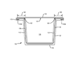
- FIG. 1 is a schematic cross-sectional view of a container according to an embodiment of the invention, but with the wall thickness of the container exaggerated for illustrative purposes.
- FIG. 2 is schematic cross-sectional view of a mold cavity according to an embodiment of the invention.
- FIG. 3 is an enlarged view of the flange portion shown in FIG. 1 .
- FIG. 4 depicts a cross-sectional view of an exemplary molding system according to various embodiments taught herein.
- FIG. 5 illustrates an exemplary computing environment suitable for practicing exemplary embodiments taught herein.
- FIG. 6 is a cross-sectional view of the fountain flow effect of a combined polymeric stream as it flows along an annular pathway of a mold cavity.
- FIGS. 7A and 7B are cross-sectional views of the velocity profile of the combined annular flow of the polymeric stream and the relative velocity differences across the flow gradient of the combined polymeric stream.
- FIG. 7C is a graph illustrating resulting flow fraction and velocity profile curves across the annular channel within a nozzle such as in FIG. 4 or for an annular channel in a mold cavity.
- exemplary co-injection molding apparatuses multi-layer molded articles and containers, and methods to form and control a barrier layer or the scavenger layer in a multi-layer molding process to ensure the integrity of the barrier layer or the scavenger layer and/or a heat seal zone during and after the implementation of a heat seal process to seal an opening in the multi-layer molded article or container.
- the container is created such that the barrier layer or the scavenger layer and/or the heat seal zone is fully intact with no breaches or weakened areas, and thus the shelf life of the container is extended.
- the integrity of the heat seal in the heat seal zone is ensured by restricting the barrier layer or the scavenger layer from contacting a heat sealable surface of the heat seal zone or becoming positioned in an area close to the surface of the heat seal zone through which it may become exposed during the heat seal process. This allows a lid or seal to be fully secured to the container at the heat seal zone. Should the barrier layer or the scavenger layer breach the heat sealable surface, before, during or after a heat seal process then a proper seal would not form between a lid or seal and the heat sealable surface, causing the shelf life of the container to decrease.
- the integrity of the barrier layer or the scavenger layer is maintained by positioning the barrier layer or the scavenger layer in the heat seal zone that does not cause the barrier layer or the scavenger layer to melt, breach or perforate during a heat seal process.
- a container 100 has a bottom 105 , a sidewall 110 extending from the periphery of the bottom 105 to form a chamber 106 , which is generally cup-shaped or U-shaped in this embodiment, having an open end 107 , and a flange 115 extending from the periphery of the sidewall 110 at the open end 107 of the container.
- a closure 120 which may be of the conventional type, may be heat-sealed to the flange 115 by conventional heat sealing methods.
- the container 100 includes a heat sealable zone 180 with a heat seal surface 182 . In this embodiment, the heat sealable zone 180 extends circumferentially about the open end 107 .
- the heat seal surface 182 extends circumferentially about the open end 107 .
- the heat sealable zone 180 and the heat seal surface 182 are formed in the flange 115 .
- the illustrative embodiment has a cup-like shape, other exemplary embodiments contemplate containers having any shape or configuration in which a heat-seal is used to seal a portion of the container.
- the container 100 may be formed by injecting a first plastic material, such as, for example, Ethylene Vinyl Alcohol (EVOH), and a second plastic material, such as, for example, Polyethylene (PE) or Polypropylene (PP) into a mold cavity configured so as to form an inner layer 130 , an interior layer 150 and an outer layer 132 generally conforming to the desired end shape of the container or article, accounting for manufacturing requirements (e.g., thermal expansion/contraction) as is known.
- PE, PP and EVOH are commonly used materials, it should be understood that other suitable materials may be used, and that the invention applies using other materials.
- either PE or PP is used to form the inner and outer layers of the resulting multi-layer article and EVOH is used to form the interior layer of the resulting multi-layer article.
- the interior layer 150 extends substantially throughout the entirety of the container 100 , but is fully surrounded by or embedded between the inner layer 130 and the outer layer 132 .
- the interior layer 150 can be a gas barrier material, such as EVOH or other suitable materials that are known or may become known, that sufficiently prevents gases, for example, oxygen, from permeating through the container, i.e., from the outside to the inside and vice versa.
- the interior layer 150 can be a gas scavenger material that sufficiently scavenges gases, for example, oxygen.
- the interior layer 150 extends into the flange 115 .
- Exemplary embodiments position and cause a leading edge of the polymeric material forming the interior layer 150 to fold over or wrap around toward the outer layer 132 within the heat-sealable zone 180 .
- the fold over portion 150 a of the interior layer 150 assures that the interior layer 150 will be encapsulated within inner and outer layers, 130 and 132 respectively, while extending substantially into the heat-sealable zone, 180 , fully around the perimeter of the container. Any gaps where the interior layer does not extend into heat-sealable zone may allow excess gas permeation into the sealed container, which is undesirable as it can shorten the shelf life of the contents held in a resulting container.
- During a heat sealing operation up to 10% or more of the thickness of the material in the heat-sealable zone 180 melts to form a gas impermeable bond between the closure and the container.
- the interior layer 150 at or just below the heat-sealable surface 182 may affect the sealing between the closure and the container because the adhesion between the first polymeric material and the closure material may not be as good as between the second polymeric material and the closure material. Further, absent the fold over portion 150 a biased toward the outer layer 132 or the inner layer 130 , the interior layer 150 does not extend into the complete perimeter of the heat-sealable zone 180 and therefore, part of the sealable portion of the container surface is not covered by barrier material, thus allowing excessive permeation of O 2 into the container contents sealed therein.
- the shelf life of the goods sealed within the container can be shortened due to the high permeation rate through the outer layer 132 .
- the fold over portion 150 a advantageously assures that interior layer 150 extends into the complete perimeter of the heat sealable zone 180 and completely around the perimeter of the part.
- the interior layer 150 via the fold over portion 150 a extends into the heat sealable zone 180 and is properly distanced from the heat sealable surface 182 . Consequently, should the interior layer 150 be positioned just below the heat sealable surface 182 then the adhesion between the heat seal closure and the container flange is considered poor, weak or does not occur. Poor or weak adhesion detrimentally allows O 2 permeation between the heat seal closure and the container.
- Proper positioning of the fold over portion 150 a in or into the heat sealable zone 180 can be advantageously performed in accordance with the teachings herein.
- water absorbed by some barrier materials for example, EVOH
- some barrier materials for example, EVOH
- the interior layer 150 were to breach the inner layer 130 of the container 100 at the heat sealable surface 182 then it is likely that the interior layer 150 would contact and adhere to the heat sealable surface 182 . If this were to occur, the heat seal closure may not fully adhere to the heat sealable surface 182 due to the contamination caused by the interior layer 150 and reduce the shelf life of the container.
- the interior layer 150 may be created by simultaneously injecting a first polymeric material forming the interior layer 150 with a second polymeric material forming the inner layer 130 and the outer layer 132 .
- Such methods are generally known, such as described in U.S. Pat. No. 6,908,581 and the documents incorporated therein, also incorporated by reference herein.
- a mold 200 has mold portions 210 a , 210 b that form a mold cavity 220 therebetween.
- a combined annular flow 300 from a nozzle assembly is injected into the mold cavity 220 through an injection gate at gate injection location 140 , and the combined annular flow 300 flows from the injection location 140 through the mold cavity 220 .
- the combined annular flow 300 is formed in the nozzle assembly.
- the nozzle assembly forms the combined annular flow 300 from the first polymeric material for the interior layer 150 and from the second polymeric material for the inner layer 130 and the outer layer 132 .
- the second polymeric material forms an inner annular flow and an outer annular flow while the first polymeric material forms an interior annular flow positioned between the inner annular flow and the outer annular flow of the combined annular flow 300 .
- the flow of the combined annular flow 300 forms a flow front 330 that moves through the mold cavity 220 .
- the volumetric flow volume ratio of the inner flow to the outer flow forming the combined annular flow 300 is selected to cause the interior layer flow stream to flow along a flow line offset from the zero velocity gradient 340 (Vmax) of the combined annular flow 300 , yet on a flow line having a greater velocity than the average flow velocity (Vave) 360 and biased toward the outer flow. This prevents the interior layer material flow 150 from breaking through the flow front 330 . Rather, the positioning and the timing of injecting the leading edge of the first polymeric material beneficially directs, as shown in FIG.
- the leading edge of the interior layer material flow 150 to enter the flange 115 and, in turn fold over toward the resulting outer layer 132 within the heat-sealable zone 180 to form the fold over portion 150 a .
- the leading edge of the first polymeric material remains behind the flow front 330 and remains encased by the inner and outer flows of the combined annular flow 300 .
- the first polymeric material of the interior layer can “catch up” to the fountain flow of the combined flow 130 and fold over, creating a barrier or scavenger layer that extends into the flange 115 and avoids failure as a barrier or scavenger during a heat sealing operation to seal the open end 107 of the container 100 .
- the fold over portion 150 a preserves the integrity of the adhesion of the interior layer 150 to the inner and outer layers and preserves the integrity of the adhesion of the closure to the heat-sealable surface 182 of the second polymeric material during and after the heat sealing operation to maintain barrier coverage or scavenger coverage in the container 100 .
- FIG. 4 illustrates an exemplary system suitable for practicing exemplary embodiments.
- Co-injection molding system 1000 is configured to inject at least two materials into a mold cavity.
- Materials suitable for use with the present invention include polymer based materials such as, Polyethylene Terephtholate (PET), Polypropylene (PP), ethylene vinyl alcohol (EVOH), and polycarbonates.
- Co-injection molding system 1000 includes a first material source 1200 , a second material source 1400 , and a manifold 1600 .
- Co-injection molding system 1000 further includes nozzle assemblies 18 A- 18 D and mold 2400 .
- Mold 2400 includes gates 20 A- 20 D, and cavities 22 A- 22 D.
- a first polymeric material is extruded from the first material source 1200 and a second polymeric material is extruded from the second material source 1400 into the manifold 1600 for combining in nozzles 18 A- 18 D before being injected into mold cavities 22 A- 22 D.
- the first and second polymeric streams are combined to form an annular combined polymeric stream such that the first polymeric material forms an interior core stream in the combined polymeric stream while the second polymeric material forms the inner and outer streams in the combined stream.
- the inner and outer streams encase the interior core stream as the annular combined polymeric stream is injected from the nozzle.
- FIG. 5 illustrates an exemplary computing environment suitable for practicing exemplary embodiments taught herein.
- the environment may include a co-injection control device 900 coupled, wired, wirelessly or a hybrid of wired and wirelessly, to co-injection system 1000 .
- the con-injection control device 900 is programmable to implement executable Barrier Protection Code 950 for forming a barrier layer or scavenger layer in a heat sealable portion of a multi-layer molded article that remains intact during and after the heat sealing operation.
- Co-injection control device 900 includes one or more computer-readable media for storing one or more computer-executable instructions or software for implementing exemplary embodiments.
- the computer-readable media may include, but are not limited to, one or more types of hardware memory, non-transitory tangible media, etc.
- memory 906 included in the co-injection control device 900 may store computer-executable instructions or software, e.g., instructions for implementing and processing every module of the executable Barrier Protection Code 950 .
- Co-injection control device 900 also includes processor 902 and, one or more processor(s) 902 ′ for executing software stored in the memory 906 , and other programs for controlling system hardware.
- Processor 902 and processor(s) 902 ′ each can be a single core processor or multiple core ( 904 and 904 ′) processor.
- Virtualization may be employed in co-injection control device 900 so that infrastructure and resources in the computing device can be shared dynamically.
- Virtualized processors may also be used with the executable Barrier Protection Code 950 and other software in storage 916 .
- a virtual machine 914 may be provided to handle a process running on multiple processors so that the process appears to be using only one computing resource rather than multiple. Multiple virtual machines can also be used with one processor.
- Memory 906 may comprise a computer system memory or random access memory, such as DRAM, SRAM, EDO RAM, etc. Memory 906 may comprise other types of memory as well, or combinations thereof.
- a user may interact with co-injection control device 900 through a visual display device 922 , such as a computer monitor, which may display the user interfaces 924 or any other interface.
- the visual display device 922 may also display other aspects or elements of exemplary embodiments, e.g. the databases, SPC historical data, etc.
- Co-injection control device 900 may include other I/O devices such a keyboard or a multi-point touch interface 908 and a pointing device 910 , for example a mouse, for receiving input from a user.
- the keyboard 908 and the pointing device 910 may be connected to the visual display device 922 .
- Co-injection control device 900 may include other suitable conventional I/O peripherals.
- Co-injection control device 900 may further comprise a storage device 916 , such as a hard-drive, CD-ROM, or other non-transitory computer readable media, for storing an operating system 918 and other related software, and for storing executable Barrier Protection Code 950 .
- a storage device 916 such as a hard-drive, CD-ROM, or other non-transitory computer readable media, for storing an operating system 918 and other related software, and for storing executable Barrier Protection Code 950 .
- Co-injection control device 900 may include a network interface 912 to interface to a Local Area Network (LAN), Wide Area Network (WAN) or the Internet through a variety of connections including, but not limited to, standard telephone lines, LAN or WAN links (e.g., 802.11, T1, T3, 56 kb, X.25), broadband connections (e.g., ISDN, Frame Relay, ATM), wireless connections, controller area network (CAN), or some combination of any or all of the above.
- the network interface 912 may comprise a built-in network adapter, network interface card, PCMCIA network card, card bus network adapter, wireless network adapter, USB network adapter, modem or any other device suitable for interfacing authorization computing device 900 to any type of network capable of communication and performing the operations described herein.
- co-injection control device 900 may be any computer system such as a workstation, desktop computer, server, laptop, handheld computer or other form of computing or telecommunications device that is capable of communication and that has sufficient processor power and memory capacity to perform the operations described herein.
- Co-injection control device 900 can be running any operating system such as any of the versions of the Microsoft® Windows® operating systems, the different releases of the Unix and Linux operating systems, any version of the MacOS® for Macintosh computers, any embedded operating system, any real-time operating system, any open source operating system, any proprietary operating system, any operating systems for mobile computing devices, or any other operating system capable of running on the computing device and performing the operations described herein.
- the operating system may be running in native mode or emulated mode.
- Barrier Protection Code 950 includes executable code executable by the processor 902 to control the co-injection system 1000 to selectively control a volumetric flow volume of the inner and outer polymeric streams, control a position of the interior core material stream 150 relative to a flow front of the combined polymeric stream and control extrusion start time of the interior core stream relative to the extrusion start time of the inner and outer polymeric streams as taught herein. That is, Barrier Protection Code 950 includes executable code executable by the processor 902 to control the co-injection system 1000 to place or direct a leading edge of the interior core material flow stream 150 on a flow streamline that has a velocity that is greater that the average velocity of the combined annular flow 300 .
- the Barrier Protection Code 950 includes executable code executable by the processor 902 to control the co-injection system 1000 to place or direct a leading edge of the interior core material flow stream 150 on a flow streamline biased toward the resulting outer layer 132 , to place or direct a leading edge of the interior core material flow stream 150 into a downstream heat sealable zone and have the leading edge of the interior core material flow stream 150 to fold over in or near the heat sealable zone to avoid a barrier layer or scavenger layer failure during or after a heat sealing process.
- the interior core material flow stream 150 folds over toward the resulting outer wall 132 .
- the Barrier Protection Code 950 allows the co-injection system 1000 to place the interior layer material flow 150 in a heat sealable zone of the resulting multi-layer plastic article to avoid a breach or failure of the interior layer 150 in the resulting multi-layer molded article during or after a heat sealing operation.
- the Barrier Protection Code 950 of the present invention aims to ensure the integrity of the interior layer 150 and ensure the integrity of the heat sealable surface 182 by restricting the interior layer 150 from contacting and contaminating the heat sealable surface 182 , as discussed previously.
- Methods and co-injection systems taught herein facilitate the co-injection molding of heat-sealable food or beverage containers whereby the interior core stream is located in a heat sealable zone to maintain its integrity during a heat sealing operation.
- FIG. 6 depicts the fountain flow effects whereby combined flow has a velocity gradient 22 such that the volumetric flow rate is fastest in the middle and slowest at or near the interface of the combined polymeric stream and the walls of the annular channels of the mold cavity.
- the flow front of the combined flow 23 shows the fountain flow effect that occurs during polymer flow between cavity walls.
- the fountain flow of polymers causes the outer surfaces of a molded part to be comprised of material that had flowed along the zero-gradient of the flow upstream of the flow front. If the interior layer flows along the zero-gradient of the combined flow, it will “fountain flow” onto the inner or outer surface of the molded part if it reaches the flow front of the combined polymer flow before the flow front reaches the end of the mold cavity.
- FIGS. 7A and 7B depicts the velocity gradient, where the combined stream is fastest at point “A” and slower at point “C”.
- the zero-velocity gradient occurs at the point where the velocity of the flow is greatest. Because the flow at the zero-velocity gradient streamline is greater than the average velocity of the flow-front, the interior material injected at the zero velocity gradient point can, under some circumstances “catch up” to and pass the flow-front and break through the skin, even if injection of the interior material begins after injection of the inner and outer layers (PET or PP). The interior core stream material will breakthrough when the interior material reaches the flow-front of the zero-velocity gradient.
- FIG. 7C plots the ratio of flow velocity-to-average flow velocity as a function of the radius of the annulus between the inner and outer flow channel walls.
- the zero gradient 340 for the combined flow stream (CF) is marked on the normalized velocity profile 350 .
- the curve designated with a circle marker plots the inner flow (IF) between the radius and the inner cylindrical wall T from the inner to the outer wall.
- the curve marked with a triangle plots the outer flow (OF) between the outer cylindrical wall and the annular radius.
- the hatched area shows the acceptable location for interior layer placement that is both greater than the average velocity and off the zero velocity gradient 340 .
- the interior layer material placed within this area will wrap to the outside of the part. From the graph we can see that the flow fraction of the outside layer can be in a range from 0.1 to 0.45.
- the flow fraction of the inside layer can be from 0.9 to 0.55.
- the interior layer thickness can be as thick as about 25% of the thickness of the flowing layer which is about 35% of the flow fraction, 0.1 to 0.45. If the hatched area were on the opposite side of the zero velocity gradient 340 , the flow fraction of the inside layer and outside layer would be of similar magnitude, but inversed, and the interior layer would then wrap toward the inside wall.
- Exemplary embodiments have the foldover biased away from the heat-sealable surface when the adhesion between the closure and the container flange may be affected by the adhesion of the interior layer material, the inner layer material and/or the closure material to each other.
- Other embodiments may have the interior layer biased toward the heat-sealable zone when closure adhesion is not adversely affected by the proximity of the interior layer to the heat-sealable surface.
Landscapes
- Engineering & Computer Science (AREA)
- Mechanical Engineering (AREA)
- Manufacturing & Machinery (AREA)
- Injection Moulding Of Plastics Or The Like (AREA)
- Moulds For Moulding Plastics Or The Like (AREA)
Abstract
Description
Claims (14)
Priority Applications (3)
| Application Number | Priority Date | Filing Date | Title |
|---|---|---|---|
| US13/303,758 US8801991B2 (en) | 2010-11-24 | 2011-11-23 | Heat-seal failure prevention method and article |
| US14/455,533 US9592652B2 (en) | 2010-11-24 | 2014-08-08 | Heat-seal failure prevention apparatus |
| US15/457,254 US20170182688A1 (en) | 2010-11-24 | 2017-03-13 | Heat-seal failure prevention method and article |
Applications Claiming Priority (2)
| Application Number | Priority Date | Filing Date | Title |
|---|---|---|---|
| US41690310P | 2010-11-24 | 2010-11-24 | |
| US13/303,758 US8801991B2 (en) | 2010-11-24 | 2011-11-23 | Heat-seal failure prevention method and article |
Related Child Applications (1)
| Application Number | Title | Priority Date | Filing Date |
|---|---|---|---|
| US14/455,533 Continuation US9592652B2 (en) | 2010-11-24 | 2014-08-08 | Heat-seal failure prevention apparatus |
Publications (2)
| Publication Number | Publication Date |
|---|---|
| US20120135171A1 US20120135171A1 (en) | 2012-05-31 |
| US8801991B2 true US8801991B2 (en) | 2014-08-12 |
Family
ID=45094305
Family Applications (3)
| Application Number | Title | Priority Date | Filing Date |
|---|---|---|---|
| US13/303,758 Active 2031-12-17 US8801991B2 (en) | 2010-11-24 | 2011-11-23 | Heat-seal failure prevention method and article |
| US14/455,533 Active US9592652B2 (en) | 2010-11-24 | 2014-08-08 | Heat-seal failure prevention apparatus |
| US15/457,254 Abandoned US20170182688A1 (en) | 2010-11-24 | 2017-03-13 | Heat-seal failure prevention method and article |
Family Applications After (2)
| Application Number | Title | Priority Date | Filing Date |
|---|---|---|---|
| US14/455,533 Active US9592652B2 (en) | 2010-11-24 | 2014-08-08 | Heat-seal failure prevention apparatus |
| US15/457,254 Abandoned US20170182688A1 (en) | 2010-11-24 | 2017-03-13 | Heat-seal failure prevention method and article |
Country Status (7)
| Country | Link |
|---|---|
| US (3) | US8801991B2 (en) |
| EP (1) | EP2643136B1 (en) |
| JP (2) | JP6035609B2 (en) |
| CN (1) | CN103347672B (en) |
| CA (1) | CA2818880C (en) |
| PT (1) | PT2643136T (en) |
| WO (1) | WO2012071497A1 (en) |
Cited By (8)
| Publication number | Priority date | Publication date | Assignee | Title |
|---|---|---|---|---|
| US9114906B2 (en) | 2011-10-21 | 2015-08-25 | Kortec, Inc. | Non-symmetric multiple layer injection molded products and methods |
| US9221204B2 (en) | 2013-03-14 | 2015-12-29 | Kortec, Inc. | Techniques to mold parts with injection-formed aperture in gate area |
| US9592652B2 (en) | 2010-11-24 | 2017-03-14 | Milacron Llc | Heat-seal failure prevention apparatus |
| US9701047B2 (en) | 2013-03-15 | 2017-07-11 | Milacron Llc | Methods and systems for the preparation of molded plastic articles having a structural barrier layer |
| US9862128B2 (en) | 2013-03-14 | 2018-01-09 | Milacron Llc | Individual cavity flow control methods and systems for co-injection molding |
| US10759101B2 (en) | 2014-01-24 | 2020-09-01 | Milacron Llc | Co-injection molded multi-layer article with injection-formed aperture between gate area and peripheral edge |
| US10843395B2 (en) | 2017-11-21 | 2020-11-24 | Gateway Plastics, Inc. | Multi-layer injection molded container |
| US11577446B2 (en) | 2015-12-29 | 2023-02-14 | Whirlpool Corporation | Molded gas barrier parts for vacuum insulated structure |
Families Citing this family (10)
| Publication number | Priority date | Publication date | Assignee | Title |
|---|---|---|---|---|
| US8308470B2 (en) * | 2005-11-04 | 2012-11-13 | University Of Southern California | Extrusion of cementitious material with different curing rates |
| US9511526B2 (en) | 2011-08-23 | 2016-12-06 | Milacron Llc | Methods and systems for the preparation of molded plastic articles having a structural barrier layer |
| US9726438B2 (en) * | 2013-01-14 | 2017-08-08 | Nanopore Incorporated | Production of thermal insulation products |
| US20170174417A1 (en) | 2013-07-01 | 2017-06-22 | Nestec S.A. | Capsule For Preparing A Beverage Such As Coffee And The Like |
| CN105392606A (en) * | 2013-07-12 | 2016-03-09 | 普拉斯蒂派克包装公司 | Co-injection method, preform, and container |
| EP3060498B1 (en) * | 2013-10-22 | 2017-06-14 | Nestec S.A. | Capsule for preparing a beverage such as coffee and the like |
| PL3030503T3 (en) | 2013-12-03 | 2018-08-31 | Biserkon Holdings Ltd. | Capsule and device for preparing beverages and method for producing capsules |
| WO2015164569A1 (en) * | 2014-04-25 | 2015-10-29 | Corning Incorporated | Apparatus and method of manufacturing composite glass articles |
| WO2016168505A1 (en) * | 2015-04-16 | 2016-10-20 | Stryker Corporation | System and method for manufacturing variable stiffness catheters |
| BR112018070236B1 (en) | 2016-04-07 | 2022-10-04 | Société Des Produits Nestlé S.A | CAPSULE DESIGNED FOR FOOD AND BEVERAGE PREPARATION |
Citations (29)
| Publication number | Priority date | Publication date | Assignee | Title |
|---|---|---|---|---|
| US2418856A (en) | 1939-06-20 | 1947-04-15 | French Oil Mill Machinery | Method of and apparatus for injection molding |
| US3339240A (en) | 1965-07-29 | 1967-09-05 | Nat Distillers Chem Corp | Apparatus for laminar injection molding |
| US3679119A (en) | 1970-06-01 | 1972-07-25 | Keith Philip Copping | Injection moulded plastic cup-like article |
| US3944124A (en) | 1971-07-28 | 1976-03-16 | Schmalbach-Lubeca-Werke Ag | Plastic containers |
| US4174413A (en) | 1976-07-27 | 1979-11-13 | Asahi-Dow Limited | Multi-layered molded articles |
| US4554190A (en) | 1983-04-13 | 1985-11-19 | American Can Company | Plastic containers with folded-over internal layers and methods for making same |
| US4568261A (en) | 1979-07-20 | 1986-02-04 | American Can Company | Apparatus for making a multi-layer injection blow molded container |
| US4751035A (en) * | 1983-04-13 | 1988-06-14 | American National Can Company | Plastic containers with folded-over internal layers and methods for making same |
| US4946365A (en) | 1983-04-13 | 1990-08-07 | American National Can Company | Apparatus for injection molding and injection blow molding multi-layer articles |
| US4990301A (en) | 1989-01-25 | 1991-02-05 | Continental Pet Technologies, Inc. | Method and apparatus for injection molding of multilayer preforms |
| EP0419829A2 (en) | 1989-09-26 | 1991-04-03 | Klöckner Ferromatik Desma GmbH | Method and apparatus for making containers for foodstuffs and the like |
| JPH0584787A (en) | 1991-09-27 | 1993-04-06 | Asahi Chem Ind Co Ltd | Mold for blow injection molding |
| JPH06190860A (en) | 1992-12-26 | 1994-07-12 | Toyota Auto Body Co Ltd | Sandwich injection molding device |
| JPH06278164A (en) | 1993-03-25 | 1994-10-04 | Toppan Printing Co Ltd | Non-circular symmetric multi-layer injected container |
| US5433910A (en) | 1991-05-14 | 1995-07-18 | Toyoda Gosei Co., Ltd. | Method of producing molding |
| US5914138A (en) | 1996-09-27 | 1999-06-22 | Kortec, Inc. | Apparatus for throttle-valving control for the co-extrusion of plastic materials as interior core streams encased by outer and inner streams for molding and the like |
| US6063325A (en) * | 1996-08-22 | 2000-05-16 | Continental Pet Technologies, Inc. | Method for preventing uncontrolled polymer flow in preform neck finish during packing and cooling stage |
| US6180042B1 (en) | 1995-11-08 | 2001-01-30 | Honda Giken Kogyo Kabushiki Kaisha | Process for producing molded article made of synthetic resin |
| US20020192404A1 (en) | 2001-04-06 | 2002-12-19 | Kortec, Inc. | Method of and apparatus for molding multi-layer polymer plastic articles having inner, outer and interior or core layers with control of relative volumetric flow rates of the inner and outer layers, enabling relative shifting of the position of the core layer and control of the relative thickness of the inner and outer layers in the molded articles |
| WO2003064133A1 (en) | 2002-01-31 | 2003-08-07 | Kortec, Inc. | Optimized flow to prevent core layer breakthrough |
| US6787097B1 (en) | 2003-06-20 | 2004-09-07 | Lear Corporation | Multiple cavity gas assisted plastic injection molding |
| US20040265422A1 (en) | 2003-05-20 | 2004-12-30 | Kortec, Inc. | Apparatus and method for fluid distribution |
| WO2005018909A1 (en) | 2003-08-18 | 2005-03-03 | Kortec, Inc. | Automatic process control for a multilayer injection molding apparatus |
| US6908581B2 (en) | 2001-04-06 | 2005-06-21 | Kortec, Inc. | Optimized flow to prevent core layer breakthrough |
| WO2007006163A1 (en) | 2005-07-08 | 2007-01-18 | Sig Technology Ltd. | Oxygen impermeable pourer with spout and flange for cardboard composite packagings |
| US20090152280A1 (en) | 2007-12-13 | 2009-06-18 | Frano Luburic | Container apparatus and related methods |
| US20090285929A1 (en) | 2008-05-14 | 2009-11-19 | Stackteck Systems Limited | Reduced thickness injection moulded part design |
| US20100044916A1 (en) | 2001-10-24 | 2010-02-25 | Ball Corporation | Polypropylene Container and Process for Making the Same |
| US20110217496A1 (en) | 2010-03-08 | 2011-09-08 | Kortec, Inc. | Method of molding multi-layer polymeric articles having control over the breakthrough of the core layer |
Family Cites Families (12)
| Publication number | Priority date | Publication date | Assignee | Title |
|---|---|---|---|---|
| US3894823A (en) | 1971-09-07 | 1975-07-15 | Robert Hanning | Apparatus for injection molding of parts of synthetic material |
| EP0307058A3 (en) * | 1983-04-13 | 1989-10-11 | American National Can Company | Co-injection nozzle devices and methods for use in molding multiple-layer articles and articles made by the methods |
| JPS61230911A (en) * | 1985-04-08 | 1986-10-15 | Toyo Seikan Kaisha Ltd | Co-injection molding device of multi-layer preforms for elongation blow molding |
| JPH03153327A (en) * | 1989-11-10 | 1991-07-01 | Dainippon Printing Co Ltd | Vessel body and manufacture thereof |
| JPH0577280A (en) * | 1991-09-19 | 1993-03-30 | Toppan Printing Co Ltd | Multi-layer injection molding |
| JP3541431B2 (en) * | 1994-06-08 | 2004-07-14 | 東洋製罐株式会社 | Oxygen absorbing container |
| US6649101B2 (en) * | 2001-07-31 | 2003-11-18 | Kortec, Inc. | Method for using a sprue to reduce the size of a core layer hole in an injection molding process by terminating an injection stream within the sprue |
| US20030087015A1 (en) | 2001-08-02 | 2003-05-08 | Ihor Wyslotsky | Modified atmosphere food container and method |
| US20050077297A1 (en) | 2003-10-09 | 2005-04-14 | Sonoco Development, Inc. | Container with easily removable membrane lid |
| US8474368B2 (en) | 2009-05-13 | 2013-07-02 | Curwood, Inc. | Mineral composite beverage brewing cup and cartridge |
| PT2643136T (en) | 2010-11-24 | 2018-07-03 | Milacron Llc | Heat-seal failure prevention method |
| US8491290B2 (en) | 2011-10-21 | 2013-07-23 | Kortec, Inc. | Apparatus for producing non-symmetric multiple layer injection molded products |
-
2011
- 2011-11-23 PT PT117911859T patent/PT2643136T/en unknown
- 2011-11-23 WO PCT/US2011/062017 patent/WO2012071497A1/en not_active Ceased
- 2011-11-23 CA CA2818880A patent/CA2818880C/en active Active
- 2011-11-23 EP EP11791185.9A patent/EP2643136B1/en active Active
- 2011-11-23 CN CN201180065913.6A patent/CN103347672B/en active Active
- 2011-11-23 JP JP2013541039A patent/JP6035609B2/en active Active
- 2011-11-23 US US13/303,758 patent/US8801991B2/en active Active
-
2014
- 2014-08-08 US US14/455,533 patent/US9592652B2/en active Active
-
2016
- 2016-10-12 JP JP2016200491A patent/JP6407935B2/en active Active
-
2017
- 2017-03-13 US US15/457,254 patent/US20170182688A1/en not_active Abandoned
Patent Citations (31)
| Publication number | Priority date | Publication date | Assignee | Title |
|---|---|---|---|---|
| US2418856A (en) | 1939-06-20 | 1947-04-15 | French Oil Mill Machinery | Method of and apparatus for injection molding |
| US3339240A (en) | 1965-07-29 | 1967-09-05 | Nat Distillers Chem Corp | Apparatus for laminar injection molding |
| US3679119A (en) | 1970-06-01 | 1972-07-25 | Keith Philip Copping | Injection moulded plastic cup-like article |
| US3944124A (en) | 1971-07-28 | 1976-03-16 | Schmalbach-Lubeca-Werke Ag | Plastic containers |
| US4174413A (en) | 1976-07-27 | 1979-11-13 | Asahi-Dow Limited | Multi-layered molded articles |
| US4568261A (en) | 1979-07-20 | 1986-02-04 | American Can Company | Apparatus for making a multi-layer injection blow molded container |
| US4554190A (en) | 1983-04-13 | 1985-11-19 | American Can Company | Plastic containers with folded-over internal layers and methods for making same |
| US4751035A (en) * | 1983-04-13 | 1988-06-14 | American National Can Company | Plastic containers with folded-over internal layers and methods for making same |
| US4946365A (en) | 1983-04-13 | 1990-08-07 | American National Can Company | Apparatus for injection molding and injection blow molding multi-layer articles |
| US4990301A (en) | 1989-01-25 | 1991-02-05 | Continental Pet Technologies, Inc. | Method and apparatus for injection molding of multilayer preforms |
| EP0419829A2 (en) | 1989-09-26 | 1991-04-03 | Klöckner Ferromatik Desma GmbH | Method and apparatus for making containers for foodstuffs and the like |
| US5433910A (en) | 1991-05-14 | 1995-07-18 | Toyoda Gosei Co., Ltd. | Method of producing molding |
| JPH0584787A (en) | 1991-09-27 | 1993-04-06 | Asahi Chem Ind Co Ltd | Mold for blow injection molding |
| JPH06190860A (en) | 1992-12-26 | 1994-07-12 | Toyota Auto Body Co Ltd | Sandwich injection molding device |
| JPH06278164A (en) | 1993-03-25 | 1994-10-04 | Toppan Printing Co Ltd | Non-circular symmetric multi-layer injected container |
| US6180042B1 (en) | 1995-11-08 | 2001-01-30 | Honda Giken Kogyo Kabushiki Kaisha | Process for producing molded article made of synthetic resin |
| US6063325A (en) * | 1996-08-22 | 2000-05-16 | Continental Pet Technologies, Inc. | Method for preventing uncontrolled polymer flow in preform neck finish during packing and cooling stage |
| US5914138A (en) | 1996-09-27 | 1999-06-22 | Kortec, Inc. | Apparatus for throttle-valving control for the co-extrusion of plastic materials as interior core streams encased by outer and inner streams for molding and the like |
| US6908581B2 (en) | 2001-04-06 | 2005-06-21 | Kortec, Inc. | Optimized flow to prevent core layer breakthrough |
| US20030124209A1 (en) * | 2001-04-06 | 2003-07-03 | Paul Swenson | Method of and apparatus for molding multi-layer polymer plastic articles having inner, outer and interior or core layers, with control of relative volumetric flow rates of the inner and outer layers enabling relative shifting of the position of the core layer and control of the relative thickness of the inner and outer layers in the molded articles |
| US20020192404A1 (en) | 2001-04-06 | 2002-12-19 | Kortec, Inc. | Method of and apparatus for molding multi-layer polymer plastic articles having inner, outer and interior or core layers with control of relative volumetric flow rates of the inner and outer layers, enabling relative shifting of the position of the core layer and control of the relative thickness of the inner and outer layers in the molded articles |
| US20100044916A1 (en) | 2001-10-24 | 2010-02-25 | Ball Corporation | Polypropylene Container and Process for Making the Same |
| WO2003064133A1 (en) | 2002-01-31 | 2003-08-07 | Kortec, Inc. | Optimized flow to prevent core layer breakthrough |
| US20040265422A1 (en) | 2003-05-20 | 2004-12-30 | Kortec, Inc. | Apparatus and method for fluid distribution |
| US6787097B1 (en) | 2003-06-20 | 2004-09-07 | Lear Corporation | Multiple cavity gas assisted plastic injection molding |
| WO2005018909A1 (en) | 2003-08-18 | 2005-03-03 | Kortec, Inc. | Automatic process control for a multilayer injection molding apparatus |
| WO2007006163A1 (en) | 2005-07-08 | 2007-01-18 | Sig Technology Ltd. | Oxygen impermeable pourer with spout and flange for cardboard composite packagings |
| US20090152280A1 (en) | 2007-12-13 | 2009-06-18 | Frano Luburic | Container apparatus and related methods |
| US20090285929A1 (en) | 2008-05-14 | 2009-11-19 | Stackteck Systems Limited | Reduced thickness injection moulded part design |
| US20110217496A1 (en) | 2010-03-08 | 2011-09-08 | Kortec, Inc. | Method of molding multi-layer polymeric articles having control over the breakthrough of the core layer |
| WO2011112613A1 (en) | 2010-03-08 | 2011-09-15 | Kortec, Inc. | Methods of molding multi-layer polymeric articles having control over the breakthrough of the core layer |
Non-Patent Citations (5)
| Title |
|---|
| F.A. Eigl et al., "Mehr Verständnis für den Kern," Kunststoffe 46-50 (Carl Hanser Verlag, Munich) (Jan. 1, 1998) (German), translated as F.A. Eigl et al., "A Better Understanding of the Core," 88:1 Kunststoffe 14-16 (Jan. 1, 1998). |
| International Search Report and Written Opinion of the International Searching Authority for International Application No. PCT/US2011/027594, mailed Sep. 29, 2012. |
| International Search Report and Written Opinion of the International Searching Authority for International Application No. PCT/US2011/062017, mailed Feb. 16, 2012. |
| International Search Report and Written Opinion of the International Searching Authority for PCT/US2012/061057, dated Feb. 12, 2013, (17 pages). |
| Naitove, Matthew H., "Multi-Layer Injection Molded Tubs Take on Thermoforming & Metal Cans," Plastics Technology, May 2011, (2 pages), available at http://www.ptonline.com/articles/multi-layer-injection-molded-tubs-take-on-thermoforming-metal-cans. |
Cited By (12)
| Publication number | Priority date | Publication date | Assignee | Title |
|---|---|---|---|---|
| US9592652B2 (en) | 2010-11-24 | 2017-03-14 | Milacron Llc | Heat-seal failure prevention apparatus |
| US9114906B2 (en) | 2011-10-21 | 2015-08-25 | Kortec, Inc. | Non-symmetric multiple layer injection molded products and methods |
| US9493269B2 (en) | 2011-10-21 | 2016-11-15 | Milacron Llc | Non-symmetric multiple layer injection molded products and methods |
| US9221204B2 (en) | 2013-03-14 | 2015-12-29 | Kortec, Inc. | Techniques to mold parts with injection-formed aperture in gate area |
| US9862128B2 (en) | 2013-03-14 | 2018-01-09 | Milacron Llc | Individual cavity flow control methods and systems for co-injection molding |
| US10144161B2 (en) | 2013-03-14 | 2018-12-04 | Milacron Llc | Individual cavity flow control methods and systems for co-injection molding |
| US10688748B2 (en) | 2013-03-14 | 2020-06-23 | Milacron Llc | Techniques to mold parts with injection-formed aperture in gate area |
| US9701047B2 (en) | 2013-03-15 | 2017-07-11 | Milacron Llc | Methods and systems for the preparation of molded plastic articles having a structural barrier layer |
| US10759101B2 (en) | 2014-01-24 | 2020-09-01 | Milacron Llc | Co-injection molded multi-layer article with injection-formed aperture between gate area and peripheral edge |
| US11577446B2 (en) | 2015-12-29 | 2023-02-14 | Whirlpool Corporation | Molded gas barrier parts for vacuum insulated structure |
| US10843395B2 (en) | 2017-11-21 | 2020-11-24 | Gateway Plastics, Inc. | Multi-layer injection molded container |
| US11298861B2 (en) | 2017-11-21 | 2022-04-12 | Silgan Specialty Packaging Llc | Multi-layer injection molded container |
Also Published As
| Publication number | Publication date |
|---|---|
| WO2012071497A1 (en) | 2012-05-31 |
| CA2818880A1 (en) | 2012-05-31 |
| CA2818880C (en) | 2019-04-30 |
| US9592652B2 (en) | 2017-03-14 |
| US20140349081A1 (en) | 2014-11-27 |
| CN103347672A (en) | 2013-10-09 |
| JP2017035890A (en) | 2017-02-16 |
| US20170182688A1 (en) | 2017-06-29 |
| EP2643136A1 (en) | 2013-10-02 |
| CN103347672B (en) | 2016-02-17 |
| PT2643136T (en) | 2018-07-03 |
| US20120135171A1 (en) | 2012-05-31 |
| EP2643136B1 (en) | 2018-06-13 |
| JP2014502224A (en) | 2014-01-30 |
| JP6407935B2 (en) | 2018-10-17 |
| JP6035609B2 (en) | 2016-11-30 |
Similar Documents
| Publication | Publication Date | Title |
|---|---|---|
| US8801991B2 (en) | Heat-seal failure prevention method and article | |
| US9114906B2 (en) | Non-symmetric multiple layer injection molded products and methods | |
| US9227349B2 (en) | Method of molding a multi-layer article | |
| US10688748B2 (en) | Techniques to mold parts with injection-formed aperture in gate area | |
| JP2014502224A5 (en) |
Legal Events
| Date | Code | Title | Description |
|---|---|---|---|
| AS | Assignment |
Owner name: KORTEC, INC., MASSACHUSETTS Free format text: ASSIGNMENT OF ASSIGNORS INTEREST;ASSIGNOR:SWENSON, PAUL M.;REEL/FRAME:027680/0001 Effective date: 20120201 |
|
| AS | Assignment |
Owner name: KORTEC, INC., MASSACHUSETTS Free format text: CHANGE OF ADDRESS OF ASSIGNEE;ASSIGNOR:KORTEC, INC.;REEL/FRAME:029626/0174 Effective date: 20120424 |
|
| STCF | Information on status: patent grant |
Free format text: PATENTED CASE |
|
| AS | Assignment |
Owner name: U.S. BANK NATIONAL ASSOCIATION, AS NOTES COLLATERA Free format text: SUPPLEMENT NO.1 TO THE AMENDED AND RESTATED INTELLECTUAL PROPERTY SECURITY AGREEMENT;ASSIGNOR:KORTEC, INC. AS GRANTOR;REEL/FRAME:033959/0001 Effective date: 20140520 Owner name: BANK OF AMERICA, N.A., AS AGENT, WISCONSIN Free format text: SUPPLEMENT NO.1 TO THE AMENDED AND RESTATED INTELLECTUAL PROPERTY SECURITY AGREEMENT;ASSIGNOR:KORTEC, INC. AS GRANTOR;REEL/FRAME:033958/0810 Effective date: 20140520 |
|
| AS | Assignment |
Owner name: BANK OF AMERICA, N.A., AS COLLATERAL AGENT, WISCON Free format text: SUPPLEMENTAL SECURITY AGREEMENT;ASSIGNORS:DME COMPANY LLC;KORTEC, INC.;MILACRON LLC;REEL/FRAME:034013/0328 Effective date: 20141017 |
|
| AS | Assignment |
Owner name: DME COMPANY LLC, MICHIGAN Free format text: RELEASE OF INTELLECTUAL PROPERTY SECURITY AGREEMENT;ASSIGNOR:U.S. BANK NATIONAL ASSOCIATION;REEL/FRAME:035668/0634 Effective date: 20150514 Owner name: KORTEC, INC., OHIO Free format text: RELEASE OF INTELLECTUAL PROPERTY SECURITY AGREEMENT;ASSIGNOR:U.S. BANK NATIONAL ASSOCIATION;REEL/FRAME:035668/0634 Effective date: 20150514 Owner name: MILACRON LLC, OHIO Free format text: RELEASE OF INTELLECTUAL PROPERTY SECURITY AGREEMENT;ASSIGNOR:U.S. BANK NATIONAL ASSOCIATION;REEL/FRAME:035668/0634 Effective date: 20150514 |
|
| AS | Assignment |
Owner name: JPMORGAN CHASE BANK, N.A., AS COLLATERAL AGENT, IL Free format text: SECURITY AGREEMENT;ASSIGNORS:MILACRON LLC;DME COMPANY LLC, A DELAWARE LIMITED LIABILITY COMPANY;KORTEC, INC., A MASSACHUSETTS CORPORATION;REEL/FRAME:035707/0098 Effective date: 20150514 |
|
| AS | Assignment |
Owner name: MILACRON LLC, OHIO Free format text: ASSIGNMENT OF ASSIGNORS INTEREST;ASSIGNOR:MILACRON MARKETING COMPANY LLC;REEL/FRAME:039781/0947 Effective date: 20160831 |
|
| AS | Assignment |
Owner name: MILACRON MARKETING COMPANY LLC, MASSACHUSETTS Free format text: MERGER;ASSIGNOR:KORTEC, INC.;REEL/FRAME:039805/0290 Effective date: 20151130 |
|
| MAFP | Maintenance fee payment |
Free format text: PAYMENT OF MAINTENANCE FEE, 4TH YEAR, LARGE ENTITY (ORIGINAL EVENT CODE: M1551) Year of fee payment: 4 |
|
| AS | Assignment |
Owner name: DME COMPANY LLC, MICHIGAN Free format text: RELEASE BY SECURED PARTY;ASSIGNOR:BANK OF AMERICA, N.A.;REEL/FRAME:051089/0551 Effective date: 20191121 Owner name: MILACRON MARKETING COMPANY LLC, OHIO Free format text: RELEASE BY SECURED PARTY;ASSIGNOR:BANK OF AMERICA, N.A.;REEL/FRAME:051089/0551 Effective date: 20191121 Owner name: MILACRON LLC, OHIO Free format text: RELEASE BY SECURED PARTY;ASSIGNOR:BANK OF AMERICA, N.A.;REEL/FRAME:051089/0551 Effective date: 20191121 Owner name: MILACRON MARKETING COMPANY LLC, OHIO Free format text: RELEASE BY SECURED PARTY;ASSIGNOR:BANK OF AMERICA, N.A.;REEL/FRAME:051089/0593 Effective date: 20191121 Owner name: MILACRON MARKETING COMPANY LLC, OHIO Free format text: RELEASE BY SECURED PARTY;ASSIGNOR:JPMORGAN CHASE BANK, N.A.;REEL/FRAME:051094/0944 Effective date: 20191121 Owner name: DME COMPANY LLC, MICHIGAN Free format text: RELEASE BY SECURED PARTY;ASSIGNOR:JPMORGAN CHASE BANK, N.A.;REEL/FRAME:051094/0944 Effective date: 20191121 Owner name: MILACRON LLC, OHIO Free format text: RELEASE BY SECURED PARTY;ASSIGNOR:JPMORGAN CHASE BANK, N.A.;REEL/FRAME:051094/0944 Effective date: 20191121 |
|
| MAFP | Maintenance fee payment |
Free format text: PAYMENT OF MAINTENANCE FEE, 8TH YEAR, LARGE ENTITY (ORIGINAL EVENT CODE: M1552); ENTITY STATUS OF PATENT OWNER: LARGE ENTITY Year of fee payment: 8 |
|
| MAFP | Maintenance fee payment |
Free format text: PAYMENT OF MAINTENANCE FEE, 12TH YEAR, LARGE ENTITY (ORIGINAL EVENT CODE: M1553); ENTITY STATUS OF PATENT OWNER: LARGE ENTITY Year of fee payment: 12 |