US8800220B1 - Precast concrete recess insert - Google Patents

Precast concrete recess insert Download PDF

Info

Publication number
US8800220B1
US8800220B1 US14/039,176 US201314039176A US8800220B1 US 8800220 B1 US8800220 B1 US 8800220B1 US 201314039176 A US201314039176 A US 201314039176A US 8800220 B1 US8800220 B1 US 8800220B1
Authority
US
United States
Prior art keywords
wall
quadrant
planar
contact
accordance
Prior art date
Legal status (The legal status is an assumption and is not a legal conclusion. Google has not performed a legal analysis and makes no representation as to the accuracy of the status listed.)
Expired - Fee Related
Application number
US14/039,176
Inventor
Sidney E. Francies, III
Current Assignee (The listed assignees may be inaccurate. Google has not performed a legal analysis and makes no representation or warranty as to the accuracy of the list.)
ALP Supply Inc
Original Assignee
Individual
Priority date (The priority date is an assumption and is not a legal conclusion. Google has not performed a legal analysis and makes no representation as to the accuracy of the date listed.)
Filing date
Publication date
Application filed by Individual filed Critical Individual
Priority to US14/039,176 priority Critical patent/US8800220B1/en
Priority to US14/456,108 priority patent/US9151065B1/en
Application granted granted Critical
Publication of US8800220B1 publication Critical patent/US8800220B1/en
Assigned to A.L. PATTERSON, INC. reassignment A.L. PATTERSON, INC. ASSIGNMENT OF ASSIGNORS INTEREST (SEE DOCUMENT FOR DETAILS). Assignors: FRANCIES, SIDNEY E., III
Expired - Fee Related legal-status Critical Current
Anticipated expiration legal-status Critical

Links

Images

Classifications

    • EFIXED CONSTRUCTIONS
    • E04BUILDING
    • E04GSCAFFOLDING; FORMS; SHUTTERING; BUILDING IMPLEMENTS OR AIDS, OR THEIR USE; HANDLING BUILDING MATERIALS ON THE SITE; REPAIRING, BREAKING-UP OR OTHER WORK ON EXISTING BUILDINGS
    • E04G21/00Preparing, conveying, or working-up building materials or building elements in situ; Other devices or measures for constructional work
    • E04G21/14Conveying or assembling building elements
    • E04G21/142Means in or on the elements for connecting same to handling apparatus
    • BPERFORMING OPERATIONS; TRANSPORTING
    • B66HOISTING; LIFTING; HAULING
    • B66CCRANES; LOAD-ENGAGING ELEMENTS OR DEVICES FOR CRANES, CAPSTANS, WINCHES, OR TACKLES
    • B66C1/00Load-engaging elements or devices attached to lifting or lowering gear of cranes or adapted for connection therewith for transmitting lifting forces to articles or groups of articles
    • B66C1/10Load-engaging elements or devices attached to lifting or lowering gear of cranes or adapted for connection therewith for transmitting lifting forces to articles or groups of articles by mechanical means
    • B66C1/62Load-engaging elements or devices attached to lifting or lowering gear of cranes or adapted for connection therewith for transmitting lifting forces to articles or groups of articles by mechanical means comprising article-engaging members of a shape complementary to that of the articles to be handled
    • B66C1/66Load-engaging elements or devices attached to lifting or lowering gear of cranes or adapted for connection therewith for transmitting lifting forces to articles or groups of articles by mechanical means comprising article-engaging members of a shape complementary to that of the articles to be handled for engaging holes, recesses, or abutments on articles specially provided for facilitating handling thereof
    • B66C1/666Load-engaging elements or devices attached to lifting or lowering gear of cranes or adapted for connection therewith for transmitting lifting forces to articles or groups of articles by mechanical means comprising article-engaging members of a shape complementary to that of the articles to be handled for engaging holes, recesses, or abutments on articles specially provided for facilitating handling thereof for connection to anchor inserts embedded in concrete structures
    • EFIXED CONSTRUCTIONS
    • E04BUILDING
    • E04GSCAFFOLDING; FORMS; SHUTTERING; BUILDING IMPLEMENTS OR AIDS, OR THEIR USE; HANDLING BUILDING MATERIALS ON THE SITE; REPAIRING, BREAKING-UP OR OTHER WORK ON EXISTING BUILDINGS
    • E04G15/00Forms or shutterings for making openings, cavities, slits, or channels
    • E04G15/04Cores for anchor holes or the like around anchors embedded in the concrete

Definitions

  • FIGS. 10A-C are schematic plan and elevation views of a recess insert according to a fifth embodiment of the invention.
  • a combination Portland cement concrete recess insert and lifting anchor may have wide applicability in environments different than that described herein.
  • the invention may be described herein in connection with one or more exemplary embodiments, all of which may share features and functionalities. A subsequent detailed description of shared features and functionalities herein may be omitted except as necessary for a complete understanding of the embodiments.
  • the invention may be utilized for other than the exemplary embodiments that may be disclosed, and such embodiments are not to be construed in any way as limiting the scope of the claims.
  • an exemplary embodiment according to the invention comprising a portion of a concrete lift assembly 10 is shown including a lift anchor 12 partially embedded in a precast Portland cement concrete shape 16 in the form of a tee.
  • the shape 16 may include embedded reinforcing bars 14 .
  • the lift anchor 12 may include a first anchor leg 20 and a second anchor leg 22 in generally parallel disposition, transitioning to an inverted somewhat vee-shaped anchor lift head 24 .
  • the first anchor leg 20 can terminate in a first anchor foot 28
  • the second anchor leg 22 can terminate in a second anchor foot 30 .
  • the planar obverse walls 52 , 56 can each be coupled orthogonally to a planar contact wall 48 along a contact line 34 .
  • the convex curved wall 46 can be coupled with the planar obverse wall 52 , 56 and the planar contact wall 48 radially opposite the contact line 34 .
  • the obverse wall 52 , 56 , planar contact wall 48 , and convex curved wall 46 can comprise a recess insert quadrant 40 , 42 having an uninterrupted surface.
  • a quadrant-shaped planar sidewall 44 can transition from the convex curved wall 46 to orthogonally intercept the planar obverse wall 52 , 56 and the planar contact wall 48 .
  • FIG. 7 illustrates a second embodiment recess insert 80 including a third recess insert quadrant 82 , and a fourth recess insert quadrant 84 .
  • the sidewalls 44 , convex curved walls 46 , and contact walls 48 are as described hereinbefore.
  • the third recess insert quadrant 82 includes a third planar obverse wall 86
  • the fourth recess insert quadrant 84 includes a fourth planar obverse wall 88 .
  • the two quadrants 82 , 84 can be coupled together through a third recess insert connector 89 , as follows.
  • the third planar obverse wall 86 differs on either side of the longitudinal plane of symmetry 26 . On one side, the obverse wall 86 extends beyond the contact wall 48 to define a connecting tab 90 having a fastener opening 98 therethrough. On the other side of the longitudinal plane of symmetry 26 , the obverse wall steps downwardly into a connecting tab recess 96 having a fastener receptacle 100 therethrough.

Landscapes

  • Engineering & Computer Science (AREA)
  • Architecture (AREA)
  • Mechanical Engineering (AREA)
  • Civil Engineering (AREA)
  • Structural Engineering (AREA)
  • Joining Of Building Structures In Genera (AREA)

Abstract

A Portland cement concrete recess insert is characterized by a quadrant shape, an obverse wall, a contact wall, and a convex wall. The obverse wall is coupled orthogonally with the contact wall along a contact line, and extends laterally of the convex wall to define a perimetric flange. The convex wall is coupled with the obverse wall and the contact wall radially opposite the contact line. A pair of recess inserts is connectable along the contact walls to define a semicircular convex wall. A bilaterally symmetrical open channel traverses the contact wall and intercepts the convex wall at two locations. The pair of recess inserts is mutually joinable along the contact walls to juxtapose the open channels and define a closed channel to enclose a portion of a lift anchor.

Description

CROSS-REFERENCE TO RELATED APPLICATION
This application claims the benefit of U.S. provisional application Ser. No. 61/707,461, filed Sep. 28, 2012, which is incorporated by reference herein in its entirety.
BACKGROUND OF THE INVENTION
The invention relates generally to a recess insert for a lifting assembly utilized in handling precast Portland cement concrete shapes. In another aspect, the invention relates to a recess insert comprising two identical coupleable pieces that can engage a lift anchor and form a cavity in the concrete so that lifting apparatuses can readily access the lift anchor for handling concrete shapes, and the recess insert can be readily removed and reused.
It is known to utilize concrete shapes that are pre-cast prior to shipment and installation on a construction project. Frequently, such shapes can be very heavy and must be removed from a mold, placed on a transporting vehicle, and installed at the construction site using lifting apparatuses, including cranes, helicopters, and other heavy equipment. Lifting apparatuses frequently include hooks, cables, chains, and the like, that couple concrete shapes with cranes, helicopters, and the like.
To facilitate coupling of hooks, cables, chains, and the like, to concrete shapes, the shapes are typically fabricated to include metallic lifting anchors integrated into the concrete. Frequently, metallic lifting anchors are attached to a recess insert which envelops that portion of the lifting anchor that must remain exposed. As fresh concrete is placed, the recess insert prevents the concrete from overflowing the exposed part of the lifting anchor. When the concrete has cured, the recess insert can be removed, and the lifting anchors will be partly embedded in the concrete and partly exposed for connecting the hooks, cables, chains, and other lifting and transporting apparatus.
Known recess inserts may be fabricated of materials that are relatively nonresistant to the corrosive effects of fresh concrete. Recess inserts may also have a configuration that is relatively ineffective at preventing fresh concrete from enveloping the exposed part of the lifting anchor, typically as a result of a recess insert design that is focused on ready removal of the recess insert from the cured concrete without specialized tools or interference from the cured concrete.
A need exists for a recess insert that is more effective at preventing the undesirable influx of fresh concrete around a lifting anchor, while enabling ready removal of the recess insert from the cured concrete.
BRIEF DESCRIPTION OF THE INVENTION
A Portland cement concrete recess insert is characterized by a quadrant shape, an obverse wall, a contact wall, and a convex wall. The obverse wall is coupled orthogonally with the contact wall along a contact line, and extends laterally of the convex wall to define a perimetric flange. The convex wall is coupled with the obverse wall and the contact wall radially opposite the contact line. A pair of recess inserts is connectable along the contact walls to define a semicircular convex wall. A bilaterally symmetrical open channel traverses the contact wall and intercepts the convex wall at two locations. The pair of recess inserts is mutually joinable along the contact walls to juxtapose the open channels and define a closed channel to enclose a portion of a lift anchor.
BRIEF DESCRIPTION OF THE DRAWINGS
FIG. 1 is a perspective view of a prefabricated concrete tee in which a cavity is formed to enable access to a concrete lift anchor according to an embodiment of the invention.
FIG. 2 is a perspective, partial cutaway view of a pair of recess inserts temporarily embedded in prefabricated concrete for forming the cavity illustrated in FIG. 1, and coupled with a concrete lift anchor.
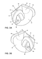
FIGS. 3A-B are perspective views of the pair of recess inserts of FIG. 2 illustrating functionalities for coupling the recess inserts together and engaging the concrete lift anchor.
FIG. 4 is a perspective view of the recess insert of FIG. 3A engaging a concrete lift anchor.
FIG. 5 is a partly cutaway elevation view of the recess insert and lift anchor of FIG. 2 oriented within precast concrete for formation of the cavity.
FIG. 6 is a perspective, partial cutaway view of a pair of recess inserts according to a second embodiment of the invention illustrating removal of the recess inserts from the cavity.
FIG. 7 is an exploded plan view of a pair of recess inserts according to a third embodiment of the invention.
FIG. 8 is a perspective, partial view of a concrete lift anchor embedded in a cavity in precast concrete and coupled with a lifting apparatus.
FIG. 9 is an elevation view of a recess insert according to a fourth embodiment of the invention.
FIGS. 10A-C are schematic plan and elevation views of a recess insert according to a fifth embodiment of the invention.
FIG. 10D is a schematic elevation view of the recess insert of FIGS. 10A-C illustrating a means of coupling a pair of recess inserts together.
DESCRIPTION OF AN EMBODIMENT OF THE INVENTION
As may be used herein, the following terms have the associated definitions unless otherwise indicated:
“Axis” means “a real or imaginary straight line about which a three-dimensional body is symmetrical or nominally symmetrical.”
“Longitudinal” with respect to a body means “correlating with the axis of a body that is parallel to the longitudinal axis of the assembled precast concrete building panel.”
“Plane of symmetry” means “a real or imaginary plane that divides a body such that each side of the body is a mirror reflection of the other.”
A combination Portland cement concrete recess insert and lifting anchor may have wide applicability in environments different than that described herein. The invention may be described herein in connection with one or more exemplary embodiments, all of which may share features and functionalities. A subsequent detailed description of shared features and functionalities herein may be omitted except as necessary for a complete understanding of the embodiments. The invention may be utilized for other than the exemplary embodiments that may be disclosed, and such embodiments are not to be construed in any way as limiting the scope of the claims.
Referring now to the figures, and to FIG. 1 in particular, an exemplary embodiment according to the invention comprising a portion of a concrete lift assembly 10 is shown including a lift anchor 12 partially embedded in a precast Portland cement concrete shape 16 in the form of a tee. The shape 16 may include embedded reinforcing bars 14. The lift anchor 12 may include a first anchor leg 20 and a second anchor leg 22 in generally parallel disposition, transitioning to an inverted somewhat vee-shaped anchor lift head 24. The first anchor leg 20 can terminate in a first anchor foot 28, and the second anchor leg 22 can terminate in a second anchor foot 30. The concrete shape 16 is characterized by a lift anchor recess 18 defining a lift anchor cavity 32 in which the lift head 24 is exposed and accessible for connecting of lifting apparatuses (not shown). The concrete lift assembly 10, including the concrete shape 16, may be characterized by a longitudinal plane of symmetry 26 dividing the concrete lift assembly 10 into two mirror images.
FIGS. 2, 3A, and 3B illustrate a first embodiment recess insert 38 for forming the lift anchor cavity 32. The recess insert 38 can comprise a pair of somewhat quadrant shaped bodies, i.e. a first recess insert quadrant 40 and a second recess insert quadrant 42. The first quadrant 40 can be characterized by a planar obverse wall 56, a planar contact wall 48, and a convex curved wall 46. The second quadrant 42 can be characterized by a planar obverse wall 52, a planar contact wall 48, and a convex curved wall 46. The planar obverse walls 52, 56 can each be coupled orthogonally to a planar contact wall 48 along a contact line 34. The convex curved wall 46 can be coupled with the planar obverse wall 52, 56 and the planar contact wall 48 radially opposite the contact line 34. Thus, the obverse wall 52, 56, planar contact wall 48, and convex curved wall 46 can comprise a recess insert quadrant 40, 42 having an uninterrupted surface.
Alternatively, as illustrated in FIGS. 2, 3A, and 3B, a quadrant-shaped planar sidewall 44 can transition from the convex curved wall 46 to orthogonally intercept the planar obverse wall 52, 56 and the planar contact wall 48.
The planar obverse wall 52, 56 can extend laterally of the longitudinal plane of symmetry 26 and the convex curved wall 46 to define a perimetric flange 50, 54. It may be recognized that the longitudinal plane of symmetry 26 is oriented orthogonal to the planar contact wall 48 and parallel to the planar sidewalls 44 and, thus, intersects the planar obverse wall 52, 56 at the furthest point from the planar contact wall 48.
In FIG. 3A, the planar contact wall 48 of the second recess insert quadrant 42 is traversed by a bilaterally symmetrical anchor lift head open channel 72. The channel 72 is characterized by an inverted vee-shape, and intercepts the convex curved wall 46 at two locations 76 (FIG. 2). The portion of the planar contact wall 48 adjacent the planar obverse wall 52 can include a first opening 66. The channel 72 separates the planar contact wall 48 into a first projection 60 having a second opening 68. The openings 66, 68 can be aligned so that an imaginary line passing diametrically through the center of each opening 66, 68 will be orthogonal to the planar obverse wall 52.
In FIG. 3B, the planar contact wall 48 of the first recess insert quadrant 40 is traversed by a bilaterally symmetrical anchor lift head open channel 70 characterized by an inverted vee-shape. The channel 70 intercepts the convex curved wall 46 at two locations 74 (FIG. 2) complementary to the two locations associated with the channel 72. The portion of the planar contact wall 48 adjacent the planar obverse wall 56 can include a first spherical head fastener 62. The channel 70 separates the planar contact wall 48 into a second projection 58 having a second spherical head fastener 64. The fasteners 62, 64 can be aligned so that an imaginary line passing diametrically through the center of each spherical head will be orthogonal to the planar obverse wall 56.
The spherical head fasteners 62, 64 and the openings 66, 68 can be adapted, respectively, for frictional engagement. The spherical head fasteners can be fabricated of a material having a suitable strength and durability for the purposes described herein. A nylon may be such a material. The spherical head fasteners may be removably insertable into openings identical to the openings 66, 68 so that as the spherical heads may wear, or become lost or broken, they can be readily replaced. Thus, the insert quadrants 40, 42 may be seen to be identical and, thus, may be fabricated using a single mold fixture or set of fixtures. Furthermore, having identical openings in both recess insert quadrants 40, 42 may enable the spherical head fastener 62 to be inserted in the opening 66, thus having one opening and one spherical head fastener for each recess insert quadrant.
Referring now to FIG. 4, a recess insert quadrant 42 is illustrated with a lift anchor head 24 received in the channel 72. The shape and depth of the channels 70, 72 will be selected based upon the size of the lift anchor. As FIG. 4 makes clear, the lift anchor can be securely retained in the channel 72, thereby minimizing movement of the lift anchor relative to the recess insert. When the recess insert quadrants 40, 42 are joined together by inserting the spherical head fasteners 62, 64 into the openings 66, 68, respectively, the lift anchor head 24 will be enveloped within the resulting closed channel. This can also be seen in FIG. 2 in which the closed channel is identified by the second lip 74 and first lip 76.
As shown in FIG. 5, the recess insert quadrants 40, 42 can be coupled together around a lift anchor head 24 along their respective planar contact walls 48. Fresh concrete 16 can be placed so that the flanges 50, 54 can extend along the surface of the concrete. The recess insert 38 can displace the concrete in order to form the cavity 32. Any fresh concrete residue, i.e. water, mortar, loose slurry, and the like, that may enter the closed channel 74, 76 will remain on the exterior of the recess insert quadrants 40, 42, and can be readily cleaned from the quadrants 40, 42 at the end of the concrete placement.
Referring now to FIG. 6, the recess insert 38 is illustrated during the process of removing the quadrants 40, 42 out of the lift anchor cavity 32 and away from the anchor lift head 24. This can be accomplished by lifting up on one of the flanges 50, 54 (in this example flange 54) and rotating the quadrant 40 out of the cavity 32. Fabricating the quadrants in order to produce and maintain smooth outer walls 44, 46 can facilitate removal of the quadrants from the cured concrete. This may be a significant factor in determining the material from which the quadrants 40, 42 may be fabricated. FIG. 6 illustrates the quadrants 40, 42 coupled together by a recess insert connector 78. The recess insert connector 78 can be a known pin-type hinge, a flat plastic piece having a flexible living hinge, a removable strap to enable use of the uncoupled quadrants 40, 42, and the like.
FIG. 7 illustrates a second embodiment recess insert 80 including a third recess insert quadrant 82, and a fourth recess insert quadrant 84. The sidewalls 44, convex curved walls 46, and contact walls 48 are as described hereinbefore. The third recess insert quadrant 82 includes a third planar obverse wall 86, and the fourth recess insert quadrant 84 includes a fourth planar obverse wall 88. The two quadrants 82, 84 can be coupled together through a third recess insert connector 89, as follows.
The third planar obverse wall 86 differs on either side of the longitudinal plane of symmetry 26. On one side, the obverse wall 86 extends beyond the contact wall 48 to define a connecting tab 90 having a fastener opening 98 therethrough. On the other side of the longitudinal plane of symmetry 26, the obverse wall steps downwardly into a connecting tab recess 96 having a fastener receptacle 100 therethrough.
It may be readily apparent that the third recess insert quadrant 82 is identical to the fourth recess insert quadrant 84. Thus, the obverse wall 88 extends beyond of the contact wall 48 to define a connecting tab 94 having a fastener opening 98 therethrough. Opposite the longitudinal plane of symmetry 26, the obverse wall steps downwardly into a connecting tab recess 92 having a fastener receptacle 100 therethrough. As illustrated in FIG. 7, the tab 90 can engage the recess 92 and the tab 94 can engage the recess 96. Threaded fasteners can be driven through the fastener openings 98 into the fastener receptacles 100 to couple the quadrants 82, 84 into a unified recess insert. As with the embodiment illustrated in FIG. 6, the quadrants 82, 84 can rotate about a hinge line for facilitating removal of the insert 82, 84 from a cavity and a lifting anchor.
FIG. 9 illustrates a third embodiment recess insert 110 adapted for use with a plate-like lift anchor 112. The lift anchor 112 is a generally elongated plate like body including a circular lift ring opening 114 and a circular anchor bar opening 116. The diameters of the openings 114, 116 can be selected based upon the size of the lifting apparatus, i.e. a lift ring, and the diameter of an anchor bar.
The recess insert 110 can be joined with an identical recess insert (not shown) in a manner generally as described herein. The recess insert 110 can have a pair of planar sidewalls 118 transitioning to a convex curved wall 120. The planar sidewalls 118 can transition to planar obverse wall 122 and a planar contact wall 124. A planar recessed wall 130 can extend parallel to and away from the contact wall 124. A lift ring opening pedestal 126 characterized by a pedestal contact face 128 can extend away from the recessed wall 130 so that the contact face 128 is coplanar with the contact wall 124. The depth of the contact wall 124 and pedestal contact face 128 can be selected to correspond with one-half the thickness of the anchor bar 112.
The lift ring opening pedestal 126 can have a coaxial opening 68. The contact wall 124 can have an opening 66. A second recess insert identical to the illustrated insert 110 can be coupled with the illustrated insert 110 by utilizing spherical head fasteners, as previously described. The lift anchor bar 112 can be placed against the recessed wall 130 with the pedestal 126 inserted through the lift ring opening 114. The second recess insert can be aligned and coupled with the illustrated insert 110 so that the lift anchor bar 112 is sandwiched between the two recess inserts, the contact walls 124 are joined together, and the pedestal contact faces 128 are joined together. As with the previously described embodiments, the recess inserts 110 can be readily separated and removed from the lift anchor cavity 32 and lift anchor 112.
FIGS. 10A-C illustrate a fourth embodiment recess insert 140 for use with a lifting pin anchor 148 having a circular lifting pin head 150 and a cylindrical lifting pin shaft 152. The recess insert 140 comprises a pair of quadrant inserts 142, 144 that can be coupled together to define a hemispherical wall 154. Each quadrant insert can have half of a conical recess 158 and half of a lifting pin head cavity 156. After the concrete has cured, the recess insert 140 can be removed from the lift anchor cavity 32 by pressing down on the center of the recess insert 140 along a pivotal joint 146, thereby urging the quadrant inserts 142, 144 away from the lifting pin anchor 148 and enabling removal of the insert 140.
FIG. 10D illustrates a fifth embodiment recess insert 160 comprising a pair of quadrant inserts 162 (only one of which is illustrated) for use with the lifting pin anchor 148. The quadrant inserts 162 have identical cavities for receiving one half of the circular lifting pin head 150 and lifting pin shaft 152 when the quadrant inserts are coupled together. The quadrant inserts 162 can each include a half flange extending along the circumference of the recess insert 160. The joining wall can be provided with recess insert connectors, 164, 166 similar to the openings and spherical head fasteners previously described herein. Removal of the recess insert 160 can be generally as described hereinbefore.
While the invention has been specifically described in connection with certain specific embodiments thereof, it is to be understood that this is by way of illustration and not of limitation. Reasonable variation and modification are possible within the scope of the forgoing disclosure and drawings without departing from the spirit of the invention which is defined in the appended claims.

Claims (23)

What is claimed is:
1. A recess insert for pre-cast Portland cement concrete shapes, the recess insert comprising:
a one-piece quadrant-shaped body characterized by a longitudinal plane of symmetry, the quadrant-shaped body including a planar obverse wall characterized by an obverse plane, a planar contact wall characterized by a contact plane, and a convex curved wall, the walls collectively joined so that the longitudinal plane of symmetry bisects each of the planar obverse wall, planar contact wall, and convex curved wall;
a perimetric flange integral with the quadrant-shaped body and coplanar with the obverse wall, beginning at the contact wall and transitioning to a triangular projection bisected by the longitudinal plane of symmetry, the perimetric flange characterized by a width adjacent the contact wall, and a depth of the triangular projection along the longitudinal plane of symmetry, the depth being greater than the width;
the contact plane and obverse plane intersecting orthogonally along a contact line disposed orthogonal to the longitudinal plane of symmetry;
the convex curved wall coupled with the planar obverse wall and the planar contact wall radially opposite the contact line;
wherein a bilaterally symmetrical open channel traverses the planar contact wall and intercepts the convex curved wall at two locations for holding a lifting anchor;
wherein a pair of quadrant-shaped bodies are mutually joinable along the planar contact walls to form the recess insert, define a closed channel to enclose a portion of a lift anchor, and define a 180° semicircular convex curved wall; and
wherein the perimetric flange is supportable upon a concrete surface, whereupon each quadrant-shaped body is individually removable from cured concrete by lifting the triangular projection away from a cured concrete surface.
2. A recess insert in accordance with claim 1 wherein a first one of the pair of quadrant-shaped bodies includes at least one opening penetrable by a fastener.
3. A recess insert in accordance with claim 2 wherein the at least one opening is in the planar contact wall.
4. A recess insert in accordance with claim 2 wherein the fastener is one of a friction fastener and a threaded fastener.
5. A recess insert in accordance with claim 4 wherein the friction fastener includes a spherical head, and the spherical head is insertable into at least one opening in a quadrant-shaped body.
6. A recess insert in accordance with claim 5 wherein a second one of the pair of quadrant-shaped bodies includes at least one opening in the planar contact wall and the spherical head is insertable therein.
7. A recess insert in accordance with claim 5 wherein the friction fastener is insertable in the at least one opening in at least one of the pair of quadrant-shaped bodies so that the spherical head projects beyond the planar contact wall.
8. A recess insert in accordance with claim 1 wherein the quadrant-shaped bodies are identical.
9. A recess insert in accordance with claim 1 wherein fresh Portland cement concrete is placeable in contact with the semicircular convex wall defined by the pair of quadrant-shaped bodies, and around a lift anchor partially receivable in the closed channel, to define a recess in placed Portland cement concrete exposing part of a lift anchor, and after at least partial curing of placed Portland cement concrete, the quadrant-shaped bodies are separable from a lift anchor by lifting the flanges away from placed Portland cement concrete to rotate the quadrant-shaped bodies out of a semicircular cavity.
10. A recess insert in accordance with claim 1 wherein a pair of quadrant-shaped bodies are connectable by a pivotal joint enabling rotation of the quadrant-shaped bodies about a transverse axis.
11. A recess insert in accordance with claim 10 wherein the pivotal joint is one of a separate flexible strap, a hinge, or an extension of the planar obverse wall.
12. A recess insert in accordance with claim 1, and further comprising a pair of opposed parallel planar sidewalls transitioning from the planar obverse wall and the planar contact wall to the convex curved wall.
13. A recess insert in accordance with claim 12 wherein the planar sidewalls transition orthogonally from the planar obverse wall and the planar-contact wall.
14. A lifting assembly for pre-cast Portland cement concrete shapes, the lifting assembly comprising:
a recess insert characterized by a longitudinal plane of symmetry, comprising a coupleable pair of one-piece quadrant-shaped bodies, each body including a planar obverse wall characterized by an obverse plane, a planar contact wall characterized by a contact plane, and a convex curved wall, the walls collectively joined so that the longitudinal plane of symmetry bisects each of the planar obverse walls, planar contact walls, and convex curved walls; and
a Portland cement concrete lifting anchor characterized by a pair of angularly disposed anchor legs joined at an angular bend;
a perimetric flange integral with a quadrant-shaped body and coplanar with the obverse wall, beginning at the contact wall and transitioning to a triangular projection bisected by the longitudinal plane of symmetry, the perimetric flange characterized by a width adjacent the contact wall, and a depth of the triangular projection along the longitudinal plane of symmetry, the depth being greater than the width;
the contact plane and obverse plane intersecting orthogonally along a contact line disposed orthogonal to the longitudinal plane of symmetry; and
the convex curved wall coupleable with the planar obverse wall and the planar contact wall radially opposite the contact line;
wherein a bilaterally symmetrical open channel traverses the planar contact wall and intercepts the convex curved wall at two locations for holding a lifting anchor; and
wherein the pair of quadrant-shaped bodies are mutually joinable along the contact walls to define a 180° semicircular convex wall, juxtapose the open channels, and define a closed channel for enclosing a portion of the lift anchor; and
wherein the perimetric flange is supportable upon a concrete surface, whereupon the recess insert is removable from cured concrete by lifting the triangular projection of each quadrant-shaped body away from a cured concrete surface.
15. A lifting assembly in accordance with claim 14 wherein a first one of the pair of quadrant-shaped bodies includes at least one opening penetrable by a fastener.
16. A lifting assembly in accordance with claim 15 wherein the at least one opening is in the planar-contact wall.
17. A lifting assembly in accordance with claim 15 wherein the fastener is one of a friction fastener and a threaded fastener.
18. A lifting assembly in accordance with claim 17 wherein the friction fastener includes a spherical head, and the spherical head is insertable into at least one opening in a quadrant-shaped body.
19. A lifting assembly in accordance with claim 18 wherein a second one of the pair of quadrant-shaped bodies includes at least one opening in the planar-contact wall and the spherical head is insertable therein.
20. A lifting assembly in accordance with claim 14 wherein the quadrant-shaped bodies are identical.
21. A lifting assembly in accordance with claim 14 wherein fresh Portland cement concrete is placeable in contact with the semicircular convex wall defined by the pair of quadrant-shaped bodies, and around the lift anchor partially received in the closed channel, to define a semicircular recess in placed Portland cement concrete exposing the angular bend, and after at least partial curing of placed Portland cement concrete, the quadrant-shaped bodies can be separated from the lift anchor by lifting the flanges away from the placed Portland cement concrete to rotate the quadrant-shaped bodies out of the semicircular recess.
22. A lifting assembly in accordance with claim 14 wherein the pair of quadrant-shaped bodies are connectable by a pivotal joint enabling rotation of the quadrant-shaped bodies about a transverse axis.
23. A lifting assembly in accordance with claim 22 wherein the pivotal joint is one of a separate flexible strap, a hinge, or an extension of the planar obverse wall.
US14/039,176 2012-09-27 2013-09-27 Precast concrete recess insert Expired - Fee Related US8800220B1 (en)

Priority Applications (2)

Application Number Priority Date Filing Date Title
US14/039,176 US8800220B1 (en) 2012-09-28 2013-09-27 Precast concrete recess insert
US14/456,108 US9151065B1 (en) 2012-09-27 2014-08-11 Precast concrete lift anchor assembly

Applications Claiming Priority (2)

Application Number Priority Date Filing Date Title
US201261707461P 2012-09-28 2012-09-28
US14/039,176 US8800220B1 (en) 2012-09-28 2013-09-27 Precast concrete recess insert

Related Parent Applications (1)

Application Number Title Priority Date Filing Date
US14/039,184 Continuation-In-Part US8898964B1 (en) 2012-09-27 2013-09-27 Lift anchor assembly for precast portland cement concrete shapes

Related Child Applications (1)

Application Number Title Priority Date Filing Date
US14/456,108 Continuation-In-Part US9151065B1 (en) 2012-09-27 2014-08-11 Precast concrete lift anchor assembly

Publications (1)

Publication Number Publication Date
US8800220B1 true US8800220B1 (en) 2014-08-12

Family

ID=51267137

Family Applications (1)

Application Number Title Priority Date Filing Date
US14/039,176 Expired - Fee Related US8800220B1 (en) 2012-09-27 2013-09-27 Precast concrete recess insert

Country Status (1)

Country Link
US (1) US8800220B1 (en)

Cited By (17)

* Cited by examiner, † Cited by third party
Publication number Priority date Publication date Assignee Title
US20170001332A1 (en) * 2015-06-30 2017-01-05 Theodore L. Kegeris Multi Piece Mold Insert for Forming a Feature in Molded or Cast Concrete Structures
US10060145B2 (en) 2016-02-29 2018-08-28 Midwest Concrete & Masonry Supply, Inc. Lifting anchor assembly for precast concrete structures
US10066406B2 (en) 2016-08-25 2018-09-04 Midwest Concrete & Masonry Supply, Inc. Erection anchor for precast insulated concrete wall panels
US10100515B2 (en) 2016-07-21 2018-10-16 Meadow Burke, Llc Lifting and leveling insert for a precast concrete slab
US20190063088A1 (en) * 2017-08-23 2019-02-28 Midwest Concrete & Masonry Supply, Inc. Lifting anchor assembly for precast concrete structures
US10232200B2 (en) * 2017-03-14 2019-03-19 Silverline Safety Systems Corp. Recessed concrete anchor
US10309103B2 (en) 2016-07-21 2019-06-04 Meadow Burke, Llc Lifting and leveling insert for a precast concrete slab
USD856121S1 (en) 2018-01-29 2019-08-13 Hk Marketing Lc Composite action tie
USD856122S1 (en) 2018-07-13 2019-08-13 Hk Marketing Lc Tie
CN110371844A (en) * 2019-07-10 2019-10-25 青岛天赢智能工业股份有限公司 A kind of flat bar suspender and its application method
US10597871B2 (en) 2016-07-21 2020-03-24 Meadow Burke, Llc Lifting and leveling insert for a precast concrete slab
USD882905S1 (en) 2018-05-31 2020-04-28 Meadow Burke, Llc Lift level
US10870988B2 (en) 2018-01-29 2020-12-22 Hk Marketing Lc Tie for composite wall system fitting between insulation sheets
US20210262217A1 (en) * 2020-02-26 2021-08-26 Ut-Battelle, Llc Non-corroding erection lifting inserts for precast insulated panels
USD938269S1 (en) * 2020-06-19 2021-12-14 Rainscreen Consulting, Llc Fastening device for rain screens
USD968199S1 (en) 2019-04-23 2022-11-01 Hk Marketing Lc Tie standoff
US20230093145A1 (en) * 2020-12-30 2023-03-23 Crh Concrete A/S A Safety Device

Citations (14)

* Cited by examiner, † Cited by third party
Publication number Priority date Publication date Assignee Title
US2838821A (en) * 1953-09-23 1958-06-17 Waldes Kohinoor Inc Snap fasteners
US4821994A (en) * 1986-09-02 1989-04-18 Siegfried Fricker Molding for the retention of a tie in the concreting of a precast concrete part
US6082700A (en) * 1998-12-17 2000-07-04 Dayton Superior Corporation Anchor positioning insert
US6095483A (en) * 1993-04-08 2000-08-01 Alan H. Reid Pty Ltd Edge lifting recess former and reinforcement system
US20020134905A1 (en) * 2001-03-26 2002-09-26 Domizio George Thomas Void forming device
US6460824B1 (en) * 1999-04-08 2002-10-08 Dayton Superior Corporation Concrete void former and cooperating cover
US20020195537A1 (en) * 2001-06-25 2002-12-26 Kelly David Lawrence Void forming and anchor positioning apparatus and method for concrete structures
US7127859B2 (en) * 2002-02-08 2006-10-31 George Domizio Hand-held void-forming system and anchor applicator
US20080196324A1 (en) * 2007-02-21 2008-08-21 Woodstock Percussion Pty Ltd Concrete Lifting Anchor
US20080203270A1 (en) * 2005-09-06 2008-08-28 Itw Construction Products Australia Pty Ltd. Void Former
US20090183441A1 (en) 2007-02-21 2009-07-23 Michael Azarin Anchor Recess Former
AU2009217422A1 (en) 2008-09-24 2010-04-08 Leviat Pty Ltd Recess Former for Concrete Panel
US20110191990A1 (en) * 2010-02-08 2011-08-11 Rodrigue Beaulieu Snap mounting clip system
WO2012140329A1 (en) * 2011-04-14 2012-10-18 Arteon, Marcel Device which is intended for forming a cavity within a construction element receiving a handling anchor, and which can be matched to the size of the anchor

Patent Citations (16)

* Cited by examiner, † Cited by third party
Publication number Priority date Publication date Assignee Title
US2838821A (en) * 1953-09-23 1958-06-17 Waldes Kohinoor Inc Snap fasteners
US4821994A (en) * 1986-09-02 1989-04-18 Siegfried Fricker Molding for the retention of a tie in the concreting of a precast concrete part
US6095483A (en) * 1993-04-08 2000-08-01 Alan H. Reid Pty Ltd Edge lifting recess former and reinforcement system
US6082700A (en) * 1998-12-17 2000-07-04 Dayton Superior Corporation Anchor positioning insert
US6460824B1 (en) * 1999-04-08 2002-10-08 Dayton Superior Corporation Concrete void former and cooperating cover
US6575424B2 (en) * 2001-03-26 2003-06-10 George Thomas Domizio Void forming device
US20020134905A1 (en) * 2001-03-26 2002-09-26 Domizio George Thomas Void forming device
US6769663B2 (en) * 2001-06-25 2004-08-03 Meadow Burke Products Void forming and anchor positioning apparatus and method for concrete structures
US20020195537A1 (en) * 2001-06-25 2002-12-26 Kelly David Lawrence Void forming and anchor positioning apparatus and method for concrete structures
US7127859B2 (en) * 2002-02-08 2006-10-31 George Domizio Hand-held void-forming system and anchor applicator
US20080203270A1 (en) * 2005-09-06 2008-08-28 Itw Construction Products Australia Pty Ltd. Void Former
US20080196324A1 (en) * 2007-02-21 2008-08-21 Woodstock Percussion Pty Ltd Concrete Lifting Anchor
US20090183441A1 (en) 2007-02-21 2009-07-23 Michael Azarin Anchor Recess Former
AU2009217422A1 (en) 2008-09-24 2010-04-08 Leviat Pty Ltd Recess Former for Concrete Panel
US20110191990A1 (en) * 2010-02-08 2011-08-11 Rodrigue Beaulieu Snap mounting clip system
WO2012140329A1 (en) * 2011-04-14 2012-10-18 Arteon, Marcel Device which is intended for forming a cavity within a construction element receiving a handling anchor, and which can be matched to the size of the anchor

Non-Patent Citations (2)

* Cited by examiner, † Cited by third party
Title
Walson Industrial Co., Limited; ARRF A-Anchor rubber recess former; http://www.walson.biz/pro-see.asp?nidn-rh393-34-54-dfd-46=67&xiaolei=778; 1 page; Copyright 2009; Shanghai, China.
Walson Industrial Co., Limited; ARRF A-Anchor rubber recess former; http://www.walson.biz/pro—see.asp?nidn—rh393—34—54—dfd—46=67&xiaolei=778; 1 page; Copyright 2009; Shanghai, China.

Cited By (24)

* Cited by examiner, † Cited by third party
Publication number Priority date Publication date Assignee Title
US20170001332A1 (en) * 2015-06-30 2017-01-05 Theodore L. Kegeris Multi Piece Mold Insert for Forming a Feature in Molded or Cast Concrete Structures
US10060145B2 (en) 2016-02-29 2018-08-28 Midwest Concrete & Masonry Supply, Inc. Lifting anchor assembly for precast concrete structures
US10309103B2 (en) 2016-07-21 2019-06-04 Meadow Burke, Llc Lifting and leveling insert for a precast concrete slab
US10100515B2 (en) 2016-07-21 2018-10-16 Meadow Burke, Llc Lifting and leveling insert for a precast concrete slab
US11060284B2 (en) 2016-07-21 2021-07-13 Meadow Burke, Llc Lifting and leveling insert for a precast concrete slab
US10597871B2 (en) 2016-07-21 2020-03-24 Meadow Burke, Llc Lifting and leveling insert for a precast concrete slab
US10066406B2 (en) 2016-08-25 2018-09-04 Midwest Concrete & Masonry Supply, Inc. Erection anchor for precast insulated concrete wall panels
US10232200B2 (en) * 2017-03-14 2019-03-19 Silverline Safety Systems Corp. Recessed concrete anchor
US20190063088A1 (en) * 2017-08-23 2019-02-28 Midwest Concrete & Masonry Supply, Inc. Lifting anchor assembly for precast concrete structures
US10837185B2 (en) * 2017-08-23 2020-11-17 Midwest Concrete & Masonry Supply, Inc. Lifting anchor assembly for precast concrete structures
US10538926B2 (en) * 2017-08-23 2020-01-21 Midwest Concrete & Masonry Supply, Inc. Lifting anchor assembly for precast concrete structures
US20200149302A1 (en) * 2017-08-23 2020-05-14 Midwest Concrete & Masonry Supply, Inc. Lifting anchor assembly for precast concrete structures
USD856121S1 (en) 2018-01-29 2019-08-13 Hk Marketing Lc Composite action tie
US10870988B2 (en) 2018-01-29 2020-12-22 Hk Marketing Lc Tie for composite wall system fitting between insulation sheets
USD887258S1 (en) 2018-01-29 2020-06-16 Hk Marketing Lc Composite action tie
USD882905S1 (en) 2018-05-31 2020-04-28 Meadow Burke, Llc Lift level
USD856122S1 (en) 2018-07-13 2019-08-13 Hk Marketing Lc Tie
USD968199S1 (en) 2019-04-23 2022-11-01 Hk Marketing Lc Tie standoff
USD1061227S1 (en) 2019-04-23 2025-02-11 Hk Marketing Lc Tie standoff
CN110371844A (en) * 2019-07-10 2019-10-25 青岛天赢智能工业股份有限公司 A kind of flat bar suspender and its application method
US20210262217A1 (en) * 2020-02-26 2021-08-26 Ut-Battelle, Llc Non-corroding erection lifting inserts for precast insulated panels
USD938269S1 (en) * 2020-06-19 2021-12-14 Rainscreen Consulting, Llc Fastening device for rain screens
US20230093145A1 (en) * 2020-12-30 2023-03-23 Crh Concrete A/S A Safety Device
US12227394B2 (en) * 2020-12-30 2025-02-18 Crh Concrete A/S Safety device

Similar Documents

Publication Publication Date Title
US8800220B1 (en) Precast concrete recess insert
US9151065B1 (en) Precast concrete lift anchor assembly
US8898964B1 (en) Lift anchor assembly for precast portland cement concrete shapes
AU626137B2 (en) Apparatus and method for lifting tilt-up wall constructions
US11530519B2 (en) Pile joint
US5226265A (en) Apparatus and method for lifting tilt-up wall constructions
US10633062B2 (en) Floating unit and a floating structure assembled from such floating units
US20210088061A1 (en) Connector Pin
US8959847B2 (en) Method and apparatus for attaching temporary lifting members to an existing lifting anchor
US11447947B2 (en) Couplings for coupling pre-cast construction segments together and pre-cast construction segments having such couplings
AU2009217422B2 (en) Recess Former for Concrete Panel
CN102686893A (en) Washer assembly and arcuate threaded fastener
TW201617533A (en) Joint, engaging device having the joint, and combination thereof
CN207761669U (en) Dodge the formula of inserting Bolt Connector
US20070101673A1 (en) Column form
NZ579819A (en) Recess former for concrete panel
JPS6073965A (en) Engaging tool for hanging concrete product
KR100328782B1 (en) The method to join a big pipe to another by it's gravity
JPH022569Y2 (en)
US12203576B1 (en) Interlocking conduit holder and spacer
CN110950443B (en) Connecting piece with buckle device for aerator
JP2000355981A (en) Coupler for precast product
JPH0748752Y2 (en) Backing liner for steel pipe pile
CN108086599A (en) Whole buckle-type grout sleeve component, external member and application grout sleeve external member realize the method that reinforcing bar effectively connects
CN210947784U (en) Building embedded part

Legal Events

Date Code Title Description
STCF Information on status: patent grant

Free format text: PATENTED CASE

MAFP Maintenance fee payment

Free format text: PAYMENT OF MAINTENANCE FEE, 4TH YR, SMALL ENTITY (ORIGINAL EVENT CODE: M2551)

Year of fee payment: 4

AS Assignment

Owner name: A.L. PATTERSON, INC., PENNSYLVANIA

Free format text: ASSIGNMENT OF ASSIGNORS INTEREST;ASSIGNOR:FRANCIES, SIDNEY E., III;REEL/FRAME:045601/0511

Effective date: 20180413

FEPP Fee payment procedure

Free format text: MAINTENANCE FEE REMINDER MAILED (ORIGINAL EVENT CODE: REM.); ENTITY STATUS OF PATENT OWNER: SMALL ENTITY

LAPS Lapse for failure to pay maintenance fees

Free format text: PATENT EXPIRED FOR FAILURE TO PAY MAINTENANCE FEES (ORIGINAL EVENT CODE: EXP.); ENTITY STATUS OF PATENT OWNER: SMALL ENTITY

STCH Information on status: patent discontinuation

Free format text: PATENT EXPIRED DUE TO NONPAYMENT OF MAINTENANCE FEES UNDER 37 CFR 1.362

FP Lapsed due to failure to pay maintenance fee

Effective date: 20220812