US8780266B2 - Video display device, display control method and recording medium - Google Patents
Video display device, display control method and recording medium Download PDFInfo
- Publication number
- US8780266B2 US8780266B2 US12/873,338 US87333810A US8780266B2 US 8780266 B2 US8780266 B2 US 8780266B2 US 87333810 A US87333810 A US 87333810A US 8780266 B2 US8780266 B2 US 8780266B2
- Authority
- US
- United States
- Prior art keywords
- image data
- video stream
- scanning line
- input
- image
- Prior art date
- Legal status (The legal status is an assumption and is not a legal conclusion. Google has not performed a legal analysis and makes no representation as to the accuracy of the status listed.)
- Expired - Fee Related, expires
Links
Images


Classifications
-
- H—ELECTRICITY
- H04—ELECTRIC COMMUNICATION TECHNIQUE
- H04N—PICTORIAL COMMUNICATION, e.g. TELEVISION
- H04N7/00—Television systems
- H04N7/01—Conversion of standards, e.g. involving analogue television standards or digital television standards processed at pixel level
- H04N7/0117—Conversion of standards, e.g. involving analogue television standards or digital television standards processed at pixel level involving conversion of the spatial resolution of the incoming video signal
- H04N7/012—Conversion between an interlaced and a progressive signal
-
- G—PHYSICS
- G09—EDUCATION; CRYPTOGRAPHY; DISPLAY; ADVERTISING; SEALS
- G09G—ARRANGEMENTS OR CIRCUITS FOR CONTROL OF INDICATING DEVICES USING STATIC MEANS TO PRESENT VARIABLE INFORMATION
- G09G5/00—Control arrangements or circuits for visual indicators common to cathode-ray tube indicators and other visual indicators
- G09G5/003—Details of a display terminal, the details relating to the control arrangement of the display terminal and to the interfaces thereto
-
- G—PHYSICS
- G09—EDUCATION; CRYPTOGRAPHY; DISPLAY; ADVERTISING; SEALS
- G09G—ARRANGEMENTS OR CIRCUITS FOR CONTROL OF INDICATING DEVICES USING STATIC MEANS TO PRESENT VARIABLE INFORMATION
- G09G2320/00—Control of display operating conditions
- G09G2320/02—Improving the quality of display appearance
- G09G2320/0209—Crosstalk reduction, i.e. to reduce direct or indirect influences of signals directed to a certain pixel of the displayed image on other pixels of said image, inclusive of influences affecting pixels in different frames or fields or sub-images which constitute a same image, e.g. left and right images of a stereoscopic display
Definitions
- the present invention relates to a video display device which displays, for example, an image on the basis of video streams by broadcasting and an image on the basis of video streams edited by an image editing software, a display control method for that video display device, and a recording medium storing a program executed by a computer controlling that video display device.
- Video streams like television broadcasting are generally transmitted in the form of interlace scanning (hereinafter, “interlacing”) image data.
- interlacing interlace scanning
- matrix-type display devices such as liquid crystal display devices, or plasma displays
- progressive scanning hereinafter, “progressive”
- Examples of a technique of converting interlacing image data into progressive image data are an inter-field scanning line interpolation process and an in-field scanning line interpolation process.
- An interpolation process inserts interpolated scanning line data in a space between individual scanning lines of interlacing image data in a video stream, thereby generating progressive image data corresponding to that video stream.
- the inter-field scanning line interpolation process and the in-field scanning line interpolation process are both interpolation processes in common, but have a following difference.
- the inter-field scanning line interpolation process uses, as interpolated scanning line data, scanning line data of previous and next fields of interlacing image data in a video stream.
- the in-field scanning line interpolation process uses, as interpolated scanning line data, scanning line data in the same field (more specifically, scanning line data right above and right below) of interlacing image data in a video stream.
- the inter-field scanning line interpolation process and the in-field scanning line interpolation process can be applied simultaneously.
- a signal processing device which changes the weighting of the inter-field scanning line interpolation process and that of the in-field scanning line interpolation process depending on the motion amount (change) of an image in a video stream is used.
- Unexamined Japanese Patent Application KOKAI Publication No. H02-196581 discloses a signal processing device which selects the in-field scanning line interpolation process if the scanning line structure of image data in a video stream does not conform to NTSC (National Television System Committee).
- PCs and cell phones have various numbers of pixels of display screen and sizes thereof, so that the number of scanning lines also varies. Accordingly, in image editing, in addition to a conversion process into the foregoing progressive image, a scaling process of the progressive image (i.e., increasing/decreasing process of the scanning lines) are performed.
- the conversion process converts interlacing image data which is an original image into progressive image data by performing an inter-field interpolation process.
- the scaling process inserts scanning line data in the field at an appropriate interval (e.g., one line for each three lines) corresponding to the enlargement ratio of a screen (e.g., 360 lines to 480 lines) to the converted progressive image data.
- the enlarged progressive image data is converted into interlacing image again.
- the interlacing image data has scanning line data of an odd-number field (field 1 ) and scanning line data of an even-number field (field 2 ) mixed in the interlacing image date four line by four line.
- FIGS. 23A to 23C are enlarged views of interlacing image data corresponding to the original image shown in FIG. 22 .
- FIGS. 24A to 24C image data having scanning lines of previous and next fields mixed therein is generated.
- FIGS. 25A to 25C image data having a position of the vertical bar shifted for each four lines is generated.
- FIG. 26 an image that a vertical line waviness (having predetermined distortions) scrolls from the left to the right is displayed.
- the present invention has been made in view of the foregoing circumstance, and it is an exemplary object of the present invention to provide a video display device, a display control method and a recording medium which suppress any image deterioration originating from image editing through a PC or a cell phone when image data that scanning lines of previous and next fields are mixed therein is displayed.
- a video display device includes: one or plurality of input paths into which a video stream is input; an inter-field scanning line interpolating unit which superimposes scanning line data of previous and next fields of interlacing image data in the video stream input from an input path among the plurality of input paths to perform inter-field scanning line interpolation, and which generates progressive image data corresponding to the video stream; a determining unit which determines whether or not a reliability of the video stream meets a predetermined level; and a selecting unit which selects image data having undergone interpolation by the inter-field scanning line interpolating unit as an image to be displayed when the determining unit determines that the reliability of the video stream does not meet the predetermined level.
- the determining unit may determine that the reliability of the video stream does not meet the predetermined level when the input path into which the video stream is input is a particular input path.
- the video display device may further include a memory which stores the video stream, wherein the particular input path is an input path into which the video stream read from the memory is input.
- the video display device may further include a receiving unit which receives the video stream via a communication network, wherein the particular input path is an input path into which the video stream received by the receiving unit is input.
- the determining unit may determine whether or not the reliability of the video stream meets the predetermined level based on identification information of the video stream.
- the identification information may be in a header of the video stream
- the determining unit may include an extracting unit which extracts the identification information from the header, and the determining unit may determine whether or not the reliability of the video stream meets the predetermined level based on the identification information extracted by the extracting unit.
- the identification information may be in a file name or an extension name of the video stream
- the determining unit may include an extracting unit which extracts the identification information from the file name or the extension name, and the determining unit may determine whether or not the reliability of the video stream meets the predetermined level based on the identification information extracted by the extracting unit.
- the video display device may further include an in-field scanning line interpolating unit which performs interpolation on interlacing image data in the video stream using scanning line data in the same field, wherein the determining unit includes a waviness detecting unit which detects a waviness of an image in the video stream based on first image data generated by the inter-field scanning line interpolating unit and second image data generated by the in-field scanning line interpolating unit, and the determining unit determines that the reliability of the video stream does not meet the predetermined level upon detection of a waviness of an image by the waviness detecting unit.
- the determining unit includes a waviness detecting unit which detects a waviness of an image in the video stream based on first image data generated by the inter-field scanning line interpolating unit and second image data generated by the in-field scanning line interpolating unit, and the determining unit determines that the reliability of the video stream does not meet the predetermined level upon detection of a waviness of an image by the
- the waviness detecting unit may detect a waviness of an image when a total number of spatial frequency components which are equal to or lower than a predetermined frequency and which are in differential image data between the first image data and the second image data is equal to or greater than a predetermined number.
- the video display device may further include: an in-field scanning line interpolating unit which performs interpolation on interlacing image data in the video stream using scanning line data in the same field; and a motion adapting unit into which image data output by the inter-field scanning line interpolating unit and image data output by the in-field scanning line interpolating unit are input, which applies image data output by the in-field scanning line interpolating unit to a part having a motion in the two pieces of image data, and which outputs image data, to which the image data output by the inter-field scanning line interpolating unit is applied, or a part having no motion in the image data, wherein the selecting unit selects image data output by the motion adapting unit as an image to be displayed when the determining unit determines that the reliability of the video stream meets the predetermined level.
- an in-field scanning line interpolating unit which performs interpolation on interlacing image data in the video stream using scanning line data in the same field
- a motion adapting unit into which image data output by the inter-field scanning line inter
- a video display device includes:
- an inter-field scanning line interpolating means which superimposes scanning line data of previous and next fields of interlacing image data in the video stream input from an input path among the plurality of input paths to perform inter-field scanning line interpolation, and which generates progressive image data corresponding to the video stream;
- a determining means which determines whether or not a reliability of the video stream meets a predetermined level
- a selecting means which selects image data having undergone interpolation by the inter-field scanning line interpolating means as an image to be displayed when the determining means determines that the reliability of the video stream does not meet the predetermined level.
- a display control method is for a video display device, the video display device including: one or plurality of input paths into which a video stream is input; and an inter-field scanning line interpolating unit which superimposes scanning line data of previous and next fields of interlacing image data in the video stream input from an input path among the plurality of input paths to perform inter-field scanning line interpolation, and which generates progressive image data corresponding to the video stream, the display control method including: a determining step of determining whether or not a reliability of the video stream meets a predetermined level; and a selecting step of selecting image data having undergone interpolation by the inter-field scanning line interpolating unit as an image to be displayed when it is determined in the determining step that the reliability of the video stream does not meet the predetermined level.
- a recording medium stores a program for a computer that controls a video display device, the video display device including: one or plurality of input paths into which a video stream is input; and an inter-field scanning line interpolating unit which superimposes scanning line data of previous and next fields of interlacing image data in the video stream input from an input path among the plurality of input paths to perform inter-field scanning line interpolation, and which generates progressive image data corresponding to the video stream, the program allowing the computer to function as: a determining unit which determines whether or not a reliability of the video stream meets a predetermined level; and a selecting unit which selects image data having undergone interpolation by the inter-field scanning line interpolating unit as an image to be displayed when the determining unit determines that the reliability of the video stream does not meet the predetermined level.
- inter-field scanning line interpolation is applied as an interpolation technique of converting interlacing image data in that video stream into progressive image data. Accordingly, periodical distortion of image data caused by image editing in the scanning line direction can be blurred. Therefore, it is possible to suppress any image deterioration when image data that scanning lines of previous and next fields are mixed therein is displayed, thereby enabling a good image display.
- FIG. 1 is a block diagram showing a configuration of a mobile terminal according to a first embodiment of the present invention
- FIG. 2 is a block diagram showing a detailed configuration of a back-end in FIG. 1 ;
- FIG. 3 is a flowchart for a first determination/selection process executed by a CPU of the mobile terminal in FIG. 1 ;
- FIG. 4A shows an example progressive image data generated by inter-field scanning line interpolation
- FIG. 4B shows an example progressive image data generated by inter-field scanning line interpolation
- FIG. 5 shows an example motion image actually displayed
- FIG. 6 is a block diagram showing a configuration of a back-end of a mobile terminal according to a second embodiment of the present invention.
- FIG. 7 is a table showing an example data format of a header of a video stream
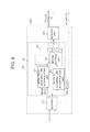
- FIG. 8 is a flowchart for a second determination/selection process executed by a decoder in FIG. 6 ;
- FIG. 9 is a block diagram showing a configuration of a mobile terminal according to a third embodiment of the present invention.
- FIG. 10 is a flowchart for a third determination/selection process executed by a CPU of the mobile terminal in FIG. 9 ;
- FIG. 11A is an exemplary diagram showing an example display image
- FIG. 11B is an exemplary diagram showing an example display image
- FIG. 11C is an exemplary diagram showing an example display image
- FIG. 12 is a block diagram showing a configuration of a back-end of a mobile terminal according to a fourth embodiment of the present invention.
- FIG. 13A is a diagram showing example image data output by an inter-field scanning line interpolating unit
- FIG. 13B is a diagram showing example image data output by the inter-field scanning line interpolating unit
- FIG. 13C is a diagram showing example image data output by the inter-field scanning line interpolating unit
- FIG. 14A is a diagram showing example image data output by an in-field scanning line interpolating unit
- FIG. 14B is a diagram showing example image data output by the in-field scanning line interpolating unit
- FIG. 14C is a diagram showing example image data output by the in-field scanning line interpolating unit
- FIG. 15A is a graph showing a power spectrum of differential image data
- FIG. 15B is a graph showing a power spectrum of differential image data
- FIG. 16 is a flowchart for an operation (a fourth determination/selection process) executed by a distortion detecting unit in FIG. 12 ;
- FIG. 17A is an exemplary diagram for explaining interlacing image data
- FIG. 17B is an exemplary diagram for explaining interlacing image data
- FIG. 18A is an exemplary diagram for explaining inter-field scanning line interpolation
- FIG. 18B is an exemplary diagram for explaining inter-field scanning line interpolation
- FIG. 19A is an exemplary diagram for explaining in-field scanning line interpolation
- FIG. 19B is an exemplary diagram for explaining in-field scanning line interpolation
- FIG. 20 is an exemplary diagram for explaining an enlargement process
- FIG. 21 is an exemplary diagram for explaining a conversion process of enlarged image data into interlacing image data
- FIG. 22 shows an example motion image as an original image displayed
- FIG. 23A is an enlarged view of interlacing image data as an original image
- FIG. 23B is an enlarged view of interlacing image data as an original image
- FIG. 23C is an enlarged view of interlacing image data as an original image
- FIG. 24A is an enlarged view of progressive image data generated by an inter-field scanning line interpolation process and an enlargement process
- FIG. 24B is an enlarged view of progressive image data generated by an inter-field scanning line interpolation process and an enlargement process
- FIG. 24C is an enlarged view of progressive image data generated by an inter-field scanning line interpolation process and an enlargement process
- FIG. 25A is an enlarged view of progressive image data edited by a video editing software
- FIG. 25B is an enlarged view of progressive image data edited by the video editing software
- FIG. 25C is an enlarged view of progressive image data edited by the video editing software.
- FIG. 26 is an example motion image actually displayed through a conventional technology.
- a video display device according to an embodiment of the present invention will be explained below with reference to the accompanying drawings.
- the explanation below will be given of an example case in which the video display device of the present invention is a mobile terminal like a cell phone.
- a mobile terminal 100 of the present embodiment comprises a communication antenna 1 , a wireless circuit 2 , a coding/decoding circuit 3 , a microphone 4 , a receiver 5 , a key 6 , a CPU (Central Processing Unit) 7 , a CPU bus 8 , a memory 9 , a DAC (Digital/Analog Converter) 10 , a speaker 11 , a video I/F 12 , an LCD (Liquid Crystal Display) controller 13 , a video I/F 14 , and a display device 15 .
- a communication antenna 1 As shown in FIG. 1 , a mobile terminal 100 of the present embodiment comprises a communication antenna 1 , a wireless circuit 2 , a coding/decoding circuit 3 , a microphone 4 , a receiver 5 , a key 6 , a CPU (Central Processing Unit) 7 , a CPU bus 8 , a memory 9 , a DAC (Digital/Analog Converter) 10 , a speaker 11 ,
- the communication antenna 1 receives a radio wave transmitted in air, and converts the radio wave into a high-frequency electrical signal.
- the converted high-frequency electrical signal is supplied to the wireless circuit 2 .
- the communication antenna 1 converts a high-frequency electrical signal supplied from the wireless circuit 2 into a radio wave, and transmits the radio wave in air.
- the wireless circuit 2 demodulates the high-frequency electrical signal converted by the communication antenna 1 , and outputs the demodulated signal to the coding/decoding circuit 3 . Moreover, the wireless circuit 2 converts an output signal by the coding/decoding circuit 3 into a high-frequency electrical signal, and outputs the converted high-frequency electrical signal to the communication antenna 1 .
- the coding/decoding circuit 3 performs decoding on the output signal by the wireless circuit 2 .
- the coding/decoding circuit 3 outputs a calling sound signal acquired as a result from the decoding to the receiver 5 .
- the coding/decoding circuit 3 outputs character data, image data, and the like acquired from the same scheme to the CPU 7 .
- the coding/decoding circuit 3 performs coding on a sound signal from the microphone 4 , character data input by an operation of the key 6 and output by the CPU 7 , and image data read-out from the memory 9 and output by the CPU 7 .
- Various data acquired as a result from the coding is output as an output signal to the wireless circuit 2 .
- the CPU 7 controls the individual structural elements of the mobile terminal 100 overall. For example, the CPU 7 detects the content of an operation of the key 6 , controls the wireless circuit 2 and the coding/decoding circuit 3 in accordance with the detected key operation, thereby to enable a verbal communication and to reproduce music or images.
- the memory 9 is connected to the CPU 7 via the CPU bus 8 .
- the memory 9 stores various control programs, and a database is built therein. More specifically, the memory 9 stores data, such as a telephone book or an address book, sound data, such as a ringer melody or music, image data, such as a motion image or a still image, and the like.
- the CPU 7 acquires a program from the memory 9 via the CPU bus 8 , and runs the program, thereby controlling the individual structural elements of the mobile terminal 100 overall.
- the CPU 7 controls the coding/decoding circuit 3 , the wireless circuit 2 , and the like, and executes, for example, a process relating to incoming-call standby.
- the CPU 7 reads out the name of a caller from the telephone book in the memory 9 , a ringer melody, and an incoming image and the like, and executes an incoming-call process.
- the CPU 7 detects an input path into which a video stream is input, and functions as a determination unit which checks the reliability of the video stream based on the detection result.
- the DAC 10 is connected to the CPU 7 via the CPU bus 8 .
- the CPU 7 outputs sound data to the DAC 10 via the CPU bus 8 .
- the DAC 10 converts a digital sound signal, such as a ring tone or a calling sound, into an analog signal, and supplies the analog signal to the speaker 11 .
- the speaker 11 outputs a ring tone or a calling sound corresponding to the analog signal supplied from the DAC 10 .
- the CPU 7 outputs the phone number of a communication party, the name thereof, image data, and the like to the LCD controller 13 via the video I/F 12 .
- An example of the video I/F 12 is a parallel bus of CMOSs, but recently, there is a trend for employing a differential serial bus from the standpoint of reduction of the number of signal lines and of noises.
- the LCD controller 13 includes a built-in VRAM (Video RAM) 30 .
- the VRAM 30 has a capacity capable of storing images by what corresponds to one screen or two screens.
- the LCD controller 13 synthesizes either one of or both of image data intermittently or partially supplied from the CPU 7 (or a back-end 18 to be discussed later) to generate a frame image. Furthermore, the LCD controller 13 successively reads out the frame image at a frequency of 60 Hz or so, and outputs such an image to the display device 15 via the video I/F 14 .
- the video I/F 14 can be a differential serial bus like the video I/F 12 , but in the present embodiment, a parallel bus of CMOSs is employed as the video I/F 14 .
- a stripe-type display device having a pixel configured by three pixels of RGB is used as the display device 15 . More specifically, devices with various numbers of pixels, such as QVGA (320 ⁇ 240 ⁇ RGB), VGA (640 ⁇ 480 ⁇ RGB), wide VGA (800 ⁇ 480 ⁇ RGB), or full-wide VGA (854 ⁇ 480 ⁇ RGB) can be used as the display device 15 . In the present embodiment, it is presumed that VGA (640 ⁇ 480 ⁇ RGB) is adopted. Moreover, let us suppose that the display device 15 is a liquid crystal display in the present embodiment.
- the mobile terminal 100 further includes a television antenna 16 , a tuner 17 , a back-end 18 , a video I/F 19 , a memory card 21 , a DAC 22 , a speaker 23 , and a back-end I/F 24 .
- the tuner 17 decodes a video/sound stream from a radio wave of television broadcasting received by the television antenna 16 , and outputs such stream to the back-end 18 .
- the back-end 18 comprises a decoder 31 , an IP converter 32 , and a resizing unit 33 .
- the decoder 31 has two input paths: an input path into which a video/sound stream is input from the tuner 17 ; and an input path into which a video/sound stream is input from the memory card 21 .
- the decoder 31 decodes a video/sound stream input from the tuner 17 , and divides it into image data (video data) and sound data.
- the IP converter 32 converts interlacing image data acquired as a result from the decoding into progressive image data. This conversion is called a progressive conversion (hereinafter, an “IP conversion”).
- the resizing unit 33 performs scaling, i.e., resizing on image data so that the image data matches the number of pixels of the display device 15 .
- the resized image data is output to the LCD controller 13 via the video I/F 19 .
- the video I/F 19 can be a differential serial bus like the video I/F 12 , but in the present embodiment, a parallel bus of CMOSs is adopted as the video I/F 19 like the video I/F 17 .
- sound data decoded by the decoder 31 is output from the speaker 23 via the DAC 22 .
- the memory card 21 can retain still images, animation image files, and files of sound only, in addition to motion image streams that the foregoing image and sound are multiplexed.
- the back-end 18 can perform the foregoing process on video/sound streams read out from the memory card 21 .
- a back-end I/F 24 is provided between the back-end 18 and the CPU 7 .
- a control command for a device connected to the back-end 18 , etc., image/sound data and the like are exchanged between the back-end 18 and the CPU 7 via the back-end I/F 24 .
- the back-end 18 includes the decoder 31 , the IP converter 32 , and the resizing unit 33 .
- the decoder 31 decodes video streams input from the tuner 17 or from the memory card 21 , and outputs image data acquired as a result from the decoding to the IP converter 32 . It is presumed that image data of the video stream is interlacing image data.
- FIG. 17A shows field 1 which is an odd-number field of the image data.
- scanning lines are arranged in odd-number lines like line 1 , line 3 , line 5 , and the like.
- FIG. 17B shows field 2 which is an even-number field of the image data.
- scanning lines are arranged in even-number lines like line 2 , line 4 , line 6 , and the like.
- the IP converter 32 includes an inter-field scanning line interpolating unit 41 , an in-field scanning line interpolating unit 42 , a motion adapting unit 43 , and a selector 44 as a selecting unit.
- a video signal input into the IP converter 32 is input into both of the inter-field scanning line interpolating unit 41 and the in-field scanning line interpolating unit 42 .
- the inter-field scanning line interpolating unit 41 superimposes scanning line data of previous and next fields of interlacing image data in a video stream (in FIG. 18A , odd-number lines of field 1 and even-number lines of field 2 , and in FIG. 18B , odd-number lines of field 3 and even-number lines of field 4 ) together to interpolate a space between the scanning lines, thereby generating progressive image data.
- Image data generated by interpolation is output to the motion adapting unit 43 .
- a highly-fine image can be acquired through inter-field scanning line interpolation because a space between scanning lines in each field is interpolated by a scanning line of a following field. According to inter-field scanning line interpolation, however, because fields different from one another in time are superimposed together and simultaneously displayed, a motion part in the image becomes a duplex image. Therefore, inter-field scanning line interpolation is proper for still image display.
- the in-field scanning line interpolating unit 42 superimposes scanning line data in the same field of interlacing image data of a video stream to interpolate a space between the scan lines, thereby generating progressive image data.
- Image data generated by interpolation is output to the motion adapting unit 43 .
- In-field scanning line interpolation interpolates a space between scanning lines in each field with scanning line data (more specifically, scanning data right above) in the same field. Although the resolution is reduced, but no duplex image is produced even if the image has a motion. Accordingly, the in-field scanning line interpolation is proper for motion image display.
- the motion adapting unit 43 detects a motion (a change) in the generated progressive image data, and determines whether such image data is a still image or a motion image. When determining that such progressive image data is a still image, the motion adapting unit 43 outputs image data input from the inter-field scanning line interpolating unit 41 (see, for example, FIGS. 18A , 18 B). When determining that such progressive image data is a motion image, the motion adapting unit 43 outputs image data input from the in-field scanning line interpolating unit 42 (see FIGS. 19A , 19 B).
- Progressive image data generated through inter-field scanning line interpolation is used for still image display.
- Progressive image data generated through in-field scanning line interpolation is used for motion image display. Accordingly, any duplexing of an image is suppressed, and a highly-fine image can be displayed regardless of a motion in the image.
- the selector 44 selectively outputs image data input from the inter-field scanning line interpolating unit 41 or image data input from the motion adapting unit 43 based on an IP conversion selecting signal 50 output by the CPU 7 .
- the resizing unit 33 enlarges or reduces the size of an image as needed in order to cause the image output by the IP converter 32 to match the number of pixels (in the present embodiment, 640 ⁇ 480) of the display device 15 , and outputs the processed image to the LCD controller 13 .
- image data with 360 lines is enlarged to image data with 480 lines
- an interpolation scanning line is inserted into image data shown in FIG. 18A for each three lines, and image data shown in FIG. 20 is thus generated.
- the scaling process of image data can be through other schemes.
- the CPU 7 When image data input from the tuner 17 is displayed, the CPU 7 outputs an IP-conversion selection signal 50 for selecting an output image by the motion adapting unit 43 to the selector 44 .
- the CPU 7 When image data input from the memory card 21 is displayed, the CPU 7 outputs an IP-conversion selection signal 50 for selecting an output image by the inter-field scanning line interpolating unit 41 to the selector 44 .
- FIG. 3 is a flowchart for a program (a first determination/selection process) executed by the CPU 7 .
- the program is run when a video stream is input into the back-end 18 .
- the CPU 7 detects an input path into which a video stream is input (step S 1 ). It is detected in this step whether a video stream input into the back-end 18 is from the tuner 17 or from the memory card 21 .
- the CPU 7 determines whether or not the video stream is input from the memory card 21 (step S 2 ).
- the CPU 7 determines that the reliability of the video stream is low, outputs the IP-conversion selection signal 50 for selecting an output by the inter-field scanning line interpolating unit 41 (step S 3 ).
- the CPU 7 determines that the reliability of the video stream is high, and outputs the IP-conversion selection signal 50 for selecting an output by the motion adapting unit 43 (step S 4 ).
- FIG. 22 an explanation will be given of a case in which a motion image that scrolls a vertical line from the left to the right is displayed.
- the CPU 7 outputs the IP-conversion selection signal 50 for selecting an output by the inter-field scanning line interpolating unit 41 to the selector 44 (step S 3 ).
- the selector 44 outputs image data input from the inter-field scanning line interpolating unit 41 to the resizing unit 33 .
- inter-field scanning line interpolation is always performed on a video stream input from the memory card 21 .
- An explanation will be given of an example case in which image data in the video stream input from the memory card 21 is edited image data having scanning lines of the previous and next fields mixed together (see, for example, FIGS. 24A to 24C ).
- progressive data containing image data of FIG. 24A and image data of FIG. 22B synthesized together is generated and progressive data containing image data of FIG. 24B and image data of FIG. 24C synthesized together is generated.
- Those pieces of progressive data are image data that a vertical bar has an edge in a comb-like shape with a fine period for each one line as shown in FIGS. 4A and 4B .
- the mobile terminal 100 It is requisite for the mobile terminal 100 to be compact as a whole, so that the physical size of the display screen of the display device 15 is small. As the display screen is small, the comb-like portions in FIGS. 4A and 4B have a period extremely small. Accordingly, as shown in FIG. 5 , the comb-like portions are perceived merely as a slight blur.
- the selector 44 selects image data input from the inter-field scanning line interpolating unit 41 , and outputs that image data to the resizing unit 33 . This makes it possible for the mobile terminal 100 to suppress any extraordinary image deterioration.
- the CPU 7 outputs the IP-conversion selection signal 50 for selecting an output by the inter-field scanning line interpolating unit 41 to the selector 44 (step S 3 ).
- the selector 44 outputs image data input from the motion adapting unit 43 to the resizing unit 33 .
- the video stream input from the tuner 17 is transmitted from a broadcasting station, so that the reliability of image data in the video stream is very high. Thus, there is an extremely low possibility that image data in the video stream is image data containing scanning lines of the previous and next fields mixed together. Accordingly, when the video stream input from the tuner 17 is played, the selector 44 selects image data output by the motion adapting unit 43 , and outputs such image data to the resizing unit 33 .
- the motion adapting unit 43 detects a change in image data, outputs image data input from the in-field scanning line interpolating unit 42 when the image data is a motion image, and outputs image data input from the inter-field scanning line interpolating unit 41 when the image data is a still image.
- the motion adapting unit 43 prevents the resolution of a still image from decreasing, and suppresses any generation of a distortion of an image in a motion image. This enables highly-fine image display.
- the reliability of image data in a video stream input from the tuner 17 is extremely high.
- image data in a video stream input from the memory card 21 is possibly edited image data containing scanning lines of the previous and next fields mixed together, and it is not always true that the reliability thereof is high. Therefore, determination by the CPU 7 of whether the input path into which a video stream is input being the input path from the tuner 17 or the input path from the memory card 21 means that it is determined whether or not the reliability of the video stream is equal to or lower than a predetermined level.
- the video display device of the present embodiment always displays with image data having undergone inter-field scanning line interpolation.
- the mobile terminal 100 of the present embodiment has two input paths into which a video stream is input, but the number of input paths may be one or equal to or greater than three.
- image data has a reliability set beforehand based on whether or not the image data input into that input path may possibly contain edited image data having scanning lines of the previous and next fields mixed, and the CPU 7 performs determination based on the set reliability.
- inter-field scanning line interpolation is always applied as an interpolation scheme of converting interlacing image data in that video stream into progressive image data. Accordingly, a periodical distortion (heave) of image data generated by video editing in the scanning line direction can be blurred. This makes it possible for the mobile terminal to suppress any image deterioration (waviness of an image) when image data containing scanning lines of the previous and next fields mixed together is displayed, thereby enabling good image display.
- inter-field scanning line interpolation and in-field scanning line interpolation are both applied depending on the motion of an image, thereby enabling image display with a high image quality.
- the mobile terminal 100 of the present embodiment has the tuner 17 and the memory card 21 both connected to the back-end 18 side.
- the present invention is, however, not limited to this configuration.
- either one of or both of the tuner 17 and the memory card 21 may be connected to the CPU 7 , and a control command, a video, sound data and the like may be exchanged therewith via the back-end I/F 24 to realized the above-explained operation.
- the mobile terminal 100 of the present embodiment differs from the mobile terminal 100 of the first embodiment that the back-end 18 has a different configuration.
- FIG. 6 shows the configuration of the back-end 18 of the present embodiment.
- the IP-conversion selection signal 50 is output by the decoder 31 , and is input into the selector 44 .
- the selector 44 is switched over in response to an instruction from the CPU 7 depending on an input path of a video stream.
- information for specifying a scanning line interpolation scheme is set in the header of a video stream.
- FIG. 7 shows an example table indicating how identification information for specifying a scanning line interpolation scheme is inserted into the header of a video stream.
- a video format is set as a first item.
- “YUV: 422” is set as the content of the video format.
- the number of pixels is set as a following second item. According to this example, “640 (H) ⁇ 480 (V)” is set as the number of pixels.
- An VP Interlace/Progressive
- I/P I/P
- a scanning line interpolation scheme is set as a following fourth item.
- “1” is set as the scanning line interpolation scheme.
- the motion adapting interpolation is an interpolation scheme of applying in-field scanning line interpolation on a part having a motion in an image which can be regarded as a motion image, and of applying inter-field scanning line interpolation on a part having no motion in an image which can be regarded as a still image.
- the item In the case of a video stream generated by recording and is not subjected to editing, or of a video stream edited with a normal interlacing structure being maintained, the item (scanning line interpolation scheme) is set to “1” by a recording device or by a video editing software. This item (scanning line interpolation scheme) is the identification information of a video stream.
- the decoder 31 When a video stream is played, the decoder 31 extracts data of this item. When the extracted data is “1”, the decoder 31 outputs the IP-conversion selection signal 50 for selecting an output image by the motion adapting unit 43 to the selector 44 . When the extracted data is not “1”, the decoder 31 outputs the IP-conversion selection signal 50 for selecting an output image by the inter-field scanning line interpolating unit 41 to the selector 44 . Like the first embodiment, the selector 44 switches image data to be output to the resizing unit 33 in accordance with the IP-conversion selection signal 50 .
- FIG. 8 is a flowchart for a program (a second determination/selection process) executed by the decoder 31 .
- This program is run when inputting of a video stream into the back-end 18 is started.
- the decoder 31 extracts data on a scanning line interpolation scheme from the header of a video stream (step S 11 ).
- the data extracted in this step indicates whether or not the video stream has a high reliability which has not been subjected to editing.
- the decoder 31 determines whether or not the extracted data is “1” (step S 12 ). When the extracted data is not “1” (step S 12 : NO), the decoder 31 outputs the IP-conversion selection signal 50 for selecting an output by the inter-field scanning line interpolating unit 41 to the selector 44 (step S 13 ). When the extracted data is “1” (step S 12 : YES), the decoder 31 outputs the IP-conversion selection signal 50 for selecting an output by the motion adapting unit 43 to the selector 44 (step S 14 ).
- the decoder 31 terminates the process.
- the reliability of a video stream is determined on the basis of the attribute of the video stream itself. Accordingly, even if a video stream input from the memory card 21 is subjected to display, when it is determined that the reliability of that video stream itself is high, a video is displayed based on image data output by the motion adapting unit 43 . As a result, displaying of a blurred image is suppressed as much as possible.
- an IP converter 72 outputs progressive image data through a motion adapting interpolation like the first embodiment.
- step S 11 which is an operation of the decoder 31 corresponds to an extracting unit.
- the motion adapting unit 43 is selected, thereby enabling display with a high image quality.
- the part of the video stream is a video stream having identification information (scanning line interpolation scheme) indicating that the video stream has not been edited (i.e., the reliability thereof is high) and set in the header of that video stream among video streams input from the memory card 21 .
- the decoder 31 or the like misses to acquire the identification information (data on a scanning line interpolation scheme) in the header of a video stream, it is desirable that the decoder 31 or the like should output the IP-conversion selection signal 50 for selecting an output by the inter-field scanning line interpolating unit 41 . This is because it can prevent an image from being distorted severely. The same is true for a case in which the identification information of a video stream is acquired but an acquired value is improper.
- identification information indicating that an image has been edited normally may be set beforehand in the fine name of the video stream or a part thereof.
- the decoder 31 extracts identification information from the file name or the like, and determines the reliability of the video stream based on the extracted data.
- the extension of a recorded video stream is set to be (***.ts).
- the extension of the video stream may be used as the identification information.
- other exclusive extensions can be also used as the identification information.
- the decoder 31 analyzes the header of a video stream.
- the CPU 7 may analyze the header of a video stream, and may directly control the selector 44 via the back-end I/F 24 .
- the selector 44 may be controlled indirectly as the CPU 7 gives a control command to the decoder 31 .
- the selector 44 is switched based on whether an input path of a video stream is from the tuner 17 or from the memory card 21 . In contrast, in the present embodiment, the selector 44 is switched based on whether an input path of a video stream is from the tuner 17 or from a wireless communication network via the wireless circuit 2 .
- the mobile terminal 100 of the present embodiment has the CPU 7 including a decoder 71 , an IP converter 72 , a resizing unit 73 , and a VRAM 74 all built in the CPU 7 .
- Those structural elements are realized as the CPU 7 runs a program stored in the memory 9 .
- the decoder 71 acquires a video stream received from the wireless communication network from the wireless circuit 2 .
- the decoder 71 decodes the acquired video stream, and outputs image data thereof.
- the IP converter 72 performs IP conversion on the image data in the video stream.
- the function of the IP converter 72 is same as that of the IP converter 32 in the first embodiment. That is, the IP converter 72 outputs either one of progressive image data generated through inter-field scanning line interpolation or progressive image data generated through motion adapting interpolation to the resizing unit 73 .
- the IP converter 72 because the IP converter 72 is built in the CPU 7 , the IP converter 72 does not need to output the IP-conversion selection signal 50 . In the present embodiment, the IP converter 72 itself determines the reliability of a video stream. Moreover, the IP converter 72 itself selects either one of the progressive image data generated through inter-field scanning line interpolation or the progressive image data generated through motion adapting interpolation based on its own determination, and outputs the selected image data.
- Video contents acquired through a wireless communication network include video contents having a low reliability, e.g., video contents edited personally. Among those pieces of video contents, there are present video contents having an image distorted as shown in FIGS. 24A to 24C for example. Therefore, in the present embodiment, the IP converter 72 performs inter-field scanning line interpolation on video contents acquired through the wireless communication network to generate progressive image data, and outputs the generated progressive image data to the resizing unit 73 .
- a video stream input from the tuner 17 is decoded by the decoder 31 of the back-end 18 , and input into the IP converter 72 in the CPU 7 via the back-end I/F 24 .
- the IP converter 72 when it is a motion image, the IP converter 72 performs in-field scanning line interpolation, and when it is a still image, the IP converter 72 performs inter-field scanning line interpolation.
- the IP converter 72 generates progressive image data, and outputs the generated progressive image data to the resizing unit 73 .
- the progressive image data is expanded in the VRAM 74 , and output to the display device 15 via the video I/F 12 .
- Sound data output by the decoder 71 and sound data transferred from the decoder 31 to the CPU 7 via the back-end I/F 24 are both output to the speaker 11 via the DAC 10 at the CPU 7 side.
- FIG. 10 is a flowchart for a program (a third determination/selection process) executed by the CPU 7 . This program is run when inputting of a video stream into the CPU 7 is started.
- the CPU 7 detects an input path into which a video stream is input (step S 21 ). It is detected whether the video stream input into the CPU 7 is from the tuner 17 or from the wireless communication network through the wireless circuit 2 .
- the CPU 7 determines whether or not the video stream is input from the wireless communication network (step S 22 ).
- the IP converter 72 in the CPU 7 selects inter-field scanning line interpolation as an interpolation scheme of generating progressive image data (step S 23 ).
- the IP converter 72 selects motion adapting interpolation as an interpolation scheme of generating progressive image data (step S 24 ).
- the mobile terminal as an output by the decoder 71 and an output by the decoder 31 are processed in a time-shearing manner and written in the VRAM 74 , as shown in FIG. 11A , it is possible for the mobile terminal to display a network image in an overlaying manner in a tuner image. Conversely, according to the present embodiment, as shown in FIG. 11B , it is also possible for the mobile terminal to display a tuner image in an overlaying manner in a network image. Furthermore, two images can be arranged in the horizontal direction or in the vertical direction and displayed, and either one of or both of the images can be displayed in an enlarged or reduced manner.
- the mobile terminal to synthesize a tuner image or a network image with graphics indicating the battery level, an electrical field intensity, and the like, an icon, a soft key, and a background image.
- IP converter 72 and the resizing unit 73 which configure a single system are used in a time-shearing manner.
- the present invention is, however, not limited to this configuration.
- IP converters 72 and resizing units 73 for configuring two systems, respectively may be provided, and an output by the decoder 71 and an output by the decoder 31 may be input into individual systems, and both image data may be eventually synthesized with each other by the VRAM 74 .
- an image corresponding to a video stream input from the tuner 17 is subjected to high-quality image display.
- any extraordinary image deterioration is suppressed by suppressing any image waviness.
- the mobile terminal it becomes possible for the mobile terminal to synthesize and display an image from the tuner 17 , an image from the wireless communication network, and an image generated by the CPU 7 together.
- the selector 44 is switched based on whether the input path of a video stream is from the tuner 17 or from the memory card 21 .
- the back-end 18 of the present embodiment further includes a waviness detecting unit 80 which detects presence/absence of any waviness of an image.
- the IP conversion scheme is switched in accordance with presence/absence of any waviness of an image.
- the waviness detecting unit 80 receives image data output by the inter-field scanning line interpolating unit 41 , and also receives image data output by the in-field scanning line interpolating unit 42 .
- the waviness detecting unit 80 compares both received image data with each other line by line or frame by frame, and acquires a differential image therefrom.
- the waviness detecting unit 80 acquires a power spectrum relative to a spatial frequency in the differential image.
- image data output by the inter-field scanning line interpolating unit 41 becomes an image including scanning lines of the previous and next fields mixed together for each one line as shown in FIGS. 13A to 13C .
- image data output by the in-field scanning line interpolating unit 42 becomes a straight-line image as shown in FIGS. 14A to 14C . Accordingly, a power spectrum of a differential image of both image data with a peak that is a relatively high frequency f 1 is acquired as shown in FIG. 15A .
- the output by the inter-field scanning line interpolating unit 41 becomes an image containing scanning lines of the previous and next fields mixed together for each three lines (see, for example, FIGS. 4A and 4B ).
- the power spectrum of this image becomes substantially same as the spectrum shown in FIG. 15A .
- the output by the in-field scanning line interpolating unit 42 becomes an image having a large waviness with an eight-line period (see, for example, FIGS. 25A to 25C ). Accordingly, as shown in FIG. 15B , in addition to a spectrum having a peak which is the frequency f 1 at the high-frequency side, a spectrum having a peak which is a frequency f 2 lower than the frequency f 1 also appears in this image.
- a frequency f 0 between the frequency f 1 and the frequency f 2 is set to be a boundary frequency.
- the waviness detecting unit 80 detects a waviness of an image when a total number S of frequency components, which are equal to or lower than the boundary frequency f 0 and which are contained in a spatial frequency component of a differential image between image data input from the inter-field scanning line interpolating unit 41 and image data input from the in-field scanning line interpolating unit 42 , is equal to or greater than a predetermined boundary number.
- FIG. 16 is a flowchart for an operation (a fourth determination/selection process) of the waviness detecting unit 80 .
- the waviness detecting unit 80 generates a differential image between image data output by the inter-field scanning line interpolating unit 41 and image data output by the in-field scanning line interpolating unit 42 (step S 31 ).
- the waviness detecting unit 80 generates a power spectrum of the differential image (step S 32 ).
- the waviness detecting unit 80 calculates the total number S of power spectra equal to or lower than the boundary frequency f 0 through the following formula (step S 33 ).
- the waviness detecting unit 80 determines whether or not the total number S is equal to or greater than the boundary number (step S 34 ). When the total number S is equal to or greater than the boundary number (step S 34 : YES), the waviness detecting unit 80 determines that an image contains a waviness, and controls the selector 44 so as to select image data output by the inter-field scanning line interpolating unit 41 (step S 35 ). When the total number S is smaller than the boundary number (step S 34 : NO), the waviness detecting unit 80 determines that an image contains no waviness, and controls the selector 44 so as to select image data output by the motion adapting unit 43 (step S 36 ).
- the waviness detecting unit 80 terminates the process.
- the waviness detecting unit 80 executes the above-explained process for each frame.
- boundary frequency and the boundary number must be set to optimized values at the time of production of the mobile terminal in accordance with the number of pixels of an input video signal. Those values may be set by a user after the product (mobile terminal) is shipped.
- the waviness detecting unit 80 detects a waviness of an image based on a difference between an output image by the inter-field scanning line interpolating unit 41 and an output image by the in-field scanning line interpolating unit 42 .
- the present invention is, however, not limited to this configuration.
- any waviness of an image can be detected through a conventionally-well-known technique like a block-matching technique.
- the motion adapting unit 43 outputs image data input from the in-field scanning line interpolating unit 42 in the case of a motion image, and outputs image data input from the inter-field scanning line interpolating unit 41 in the case of a still image.
- image data having a pixel value which is a weighted average value among individual pixel values of image data input from the in-field scanning line interpolating unit 42 and individual pixel values of image data input from the inter-field scanning line interpolating unit 41 may be output in accordance with an amount of change in image data.
- the motion adapting unit 43 makes it possible for the motion adapting unit 43 to output image data corresponding to a motion part of a motion image having undergone in-field scanning line interpolation, and to generate progressive image data having undergone inter-field scanning line interpolation regarding a still image part having no motion.
- the configuration of the mobile terminal 100 of the foregoing embodiments is merely an example, and the structural elements of the mobile terminal 100 of the foregoing embodiments can be combined together in any way.
- the display device 15 is a liquid crystal display, but may be a self-light-emitting type organic EL display.
- the present invention can be applied to various kinds of displays if such a display is small.
- the present invention can be applied to general terminal devices which can display a video, such as a PHS (Personal Handy-phone system), a PDA (Personal Digital Assistant), a PC, a television, a video recording device, and a video playing device, in addition to a cell phone.
- a video such as a PHS (Personal Handy-phone system), a PDA (Personal Digital Assistant), a PC, a television, a video recording device, and a video playing device, in addition to a cell phone.
Landscapes
- Engineering & Computer Science (AREA)
- Computer Graphics (AREA)
- Multimedia (AREA)
- Signal Processing (AREA)
- Physics & Mathematics (AREA)
- Computer Hardware Design (AREA)
- General Physics & Mathematics (AREA)
- Theoretical Computer Science (AREA)
- Television Systems (AREA)
- Controls And Circuits For Display Device (AREA)
Abstract
Description
where f is a spatial frequency and x is a spectrum at that spatial frequency.
Claims (14)
Applications Claiming Priority (2)
| Application Number | Priority Date | Filing Date | Title |
|---|---|---|---|
| JP2009202117A JP5557311B2 (en) | 2009-09-01 | 2009-09-01 | Video display device, display control method, and program |
| JP2009-202117 | 2009-09-01 |
Publications (2)
| Publication Number | Publication Date |
|---|---|
| US20110050994A1 US20110050994A1 (en) | 2011-03-03 |
| US8780266B2 true US8780266B2 (en) | 2014-07-15 |
Family
ID=43624384
Family Applications (1)
| Application Number | Title | Priority Date | Filing Date |
|---|---|---|---|
| US12/873,338 Expired - Fee Related US8780266B2 (en) | 2009-09-01 | 2010-09-01 | Video display device, display control method and recording medium |
Country Status (2)
| Country | Link |
|---|---|
| US (1) | US8780266B2 (en) |
| JP (1) | JP5557311B2 (en) |
Citations (9)
| Publication number | Priority date | Publication date | Assignee | Title |
|---|---|---|---|---|
| JPH02196581A (en) | 1989-01-26 | 1990-08-03 | Sharp Corp | Signal processing unit |
| JPH10322664A (en) | 1997-05-16 | 1998-12-04 | Toshiba Corp | Computer system and video decoder used in the system |
| JPH11331783A (en) | 1998-05-18 | 1999-11-30 | Mitsubishi Electric Corp | Scan line conversion circuit |
| JP2003169300A (en) | 2001-12-03 | 2003-06-13 | Mitsubishi Electric Corp | Video signal processing device |
| US20040125231A1 (en) * | 2002-12-30 | 2004-07-01 | Samsung Electronics Co., Ltd. | Method and apparatus for de-interlacing video signal |
| JP2005102191A (en) | 2003-09-03 | 2005-04-14 | Sony Corp | Image processing apparatus and method |
| US7268828B2 (en) * | 2003-06-30 | 2007-09-11 | Kabushiki Kaisha Toshiba | Television receiver and control method thereof for displaying video signals based on different television modes |
| JP2009111442A (en) | 2007-10-26 | 2009-05-21 | Canon Inc | Video transmission system and method |
| US20090316047A1 (en) * | 2008-06-23 | 2009-12-24 | Onkyo Corporation | Image processing apparatus |
-
2009
- 2009-09-01 JP JP2009202117A patent/JP5557311B2/en not_active Expired - Fee Related
-
2010
- 2010-09-01 US US12/873,338 patent/US8780266B2/en not_active Expired - Fee Related
Patent Citations (10)
| Publication number | Priority date | Publication date | Assignee | Title |
|---|---|---|---|---|
| JPH02196581A (en) | 1989-01-26 | 1990-08-03 | Sharp Corp | Signal processing unit |
| JPH10322664A (en) | 1997-05-16 | 1998-12-04 | Toshiba Corp | Computer system and video decoder used in the system |
| JPH11331783A (en) | 1998-05-18 | 1999-11-30 | Mitsubishi Electric Corp | Scan line conversion circuit |
| JP2003169300A (en) | 2001-12-03 | 2003-06-13 | Mitsubishi Electric Corp | Video signal processing device |
| US20040125231A1 (en) * | 2002-12-30 | 2004-07-01 | Samsung Electronics Co., Ltd. | Method and apparatus for de-interlacing video signal |
| JP2004215263A (en) | 2002-12-30 | 2004-07-29 | Samsung Electronics Co Ltd | Progressive scan conversion method and apparatus |
| US7268828B2 (en) * | 2003-06-30 | 2007-09-11 | Kabushiki Kaisha Toshiba | Television receiver and control method thereof for displaying video signals based on different television modes |
| JP2005102191A (en) | 2003-09-03 | 2005-04-14 | Sony Corp | Image processing apparatus and method |
| JP2009111442A (en) | 2007-10-26 | 2009-05-21 | Canon Inc | Video transmission system and method |
| US20090316047A1 (en) * | 2008-06-23 | 2009-12-24 | Onkyo Corporation | Image processing apparatus |
Non-Patent Citations (1)
| Title |
|---|
| JP Office Action dated May 14, 2013, with partial English translation; Application No. 2009-202117. |
Also Published As
| Publication number | Publication date |
|---|---|
| JP2011055243A (en) | 2011-03-17 |
| JP5557311B2 (en) | 2014-07-23 |
| US20110050994A1 (en) | 2011-03-03 |
Similar Documents
| Publication | Publication Date | Title |
|---|---|---|
| US6493036B1 (en) | System and method for scaling real time video | |
| KR100893808B1 (en) | Picture processing apparatus and picture processing method | |
| US7057621B2 (en) | Screen display apparatus and a method for utilizing the screen display apparatus in a mobile terminal | |
| US7006156B2 (en) | Image data output device and receiving device | |
| CN114285958B (en) | Image processing circuit, image processing method and electronic device | |
| US20100142619A1 (en) | Apparatus and method for processing image | |
| EP3099081B1 (en) | Display apparatus and control method thereof | |
| CN100576889C (en) | AV stream playback device, decoder switching method, and integrated circuit | |
| US7630576B2 (en) | Signal processing apparatus and method, and command-sequence data structure | |
| JP2003338991A (en) | Image display device and image display method | |
| JP2013040976A (en) | Image display device and image display method | |
| JP4878628B2 (en) | Video processing apparatus and video processing method | |
| US8780266B2 (en) | Video display device, display control method and recording medium | |
| JP2002199277A (en) | Image data output device | |
| US7525557B2 (en) | Moving image composition device, moving image composition method, and information terminal with moving image composition function | |
| JP4110363B2 (en) | Image processing apparatus, image processing method, and image display apparatus | |
| JP2008009182A (en) | Liquid crystal display | |
| US7492380B2 (en) | Apparatus and method for processing video signal | |
| JP2011035612A (en) | Frame rate converter and display device mounted by the same | |
| JPWO2006057133A1 (en) | Image display device | |
| US7391477B2 (en) | Apparatus and method for processing video signal | |
| JP4530671B2 (en) | Image reproducing apparatus and image reproducing method | |
| KR20050021310A (en) | Image signal processing circuit and portable terminal | |
| JP4697482B2 (en) | Image synthesizer | |
| JP4182685B2 (en) | Video signal processing apparatus and method, recording medium, and program |
Legal Events
| Date | Code | Title | Description |
|---|---|---|---|
| AS | Assignment |
Owner name: NEC CASIO MOBILE COMMUNICATIONS, LTD., JAPAN Free format text: ASSIGNMENT OF ASSIGNORS INTEREST;ASSIGNOR:MASUDA, KOZO;REEL/FRAME:024921/0288 Effective date: 20100827 |
|
| STCF | Information on status: patent grant |
Free format text: PATENTED CASE |
|
| AS | Assignment |
Owner name: NEC MOBILE COMMUNICATIONS, LTD., JAPAN Free format text: CHANGE OF NAME;ASSIGNOR:NEC CASIO MOBILE COMMUNICATIONS, LTD.;REEL/FRAME:035866/0495 Effective date: 20141002 |
|
| AS | Assignment |
Owner name: NEC CORPORATION, JAPAN Free format text: ASSIGNMENT OF ASSIGNORS INTEREST;ASSIGNOR:NEC MOBILE COMMUNICATIONS, LTD.;REEL/FRAME:036037/0476 Effective date: 20150618 |
|
| MAFP | Maintenance fee payment |
Free format text: PAYMENT OF MAINTENANCE FEE, 4TH YEAR, LARGE ENTITY (ORIGINAL EVENT CODE: M1551) Year of fee payment: 4 |
|
| FEPP | Fee payment procedure |
Free format text: MAINTENANCE FEE REMINDER MAILED (ORIGINAL EVENT CODE: REM.); ENTITY STATUS OF PATENT OWNER: LARGE ENTITY |
|
| LAPS | Lapse for failure to pay maintenance fees |
Free format text: PATENT EXPIRED FOR FAILURE TO PAY MAINTENANCE FEES (ORIGINAL EVENT CODE: EXP.); ENTITY STATUS OF PATENT OWNER: LARGE ENTITY |
|
| STCH | Information on status: patent discontinuation |
Free format text: PATENT EXPIRED DUE TO NONPAYMENT OF MAINTENANCE FEES UNDER 37 CFR 1.362 |
|
| FP | Lapsed due to failure to pay maintenance fee |
Effective date: 20220715 |