US8780261B2 - Light sensitivity calibration method and an imaging device - Google Patents
Light sensitivity calibration method and an imaging device Download PDFInfo
- Publication number
- US8780261B2 US8780261B2 US13/210,859 US201113210859A US8780261B2 US 8780261 B2 US8780261 B2 US 8780261B2 US 201113210859 A US201113210859 A US 201113210859A US 8780261 B2 US8780261 B2 US 8780261B2
- Authority
- US
- United States
- Prior art keywords
- mode
- capture
- light sensitivity
- preview
- image
- Prior art date
- Legal status (The legal status is an assumption and is not a legal conclusion. Google has not performed a legal analysis and makes no representation as to the accuracy of the status listed.)
- Active, expires
Links
Images


Classifications
-
- H—ELECTRICITY
- H04—ELECTRIC COMMUNICATION TECHNIQUE
- H04N—PICTORIAL COMMUNICATION, e.g. TELEVISION
- H04N23/00—Cameras or camera modules comprising electronic image sensors; Control thereof
- H04N23/60—Control of cameras or camera modules
- H04N23/667—Camera operation mode switching, e.g. between still and video, sport and normal or high- and low-resolution modes
-
- H—ELECTRICITY
- H04—ELECTRIC COMMUNICATION TECHNIQUE
- H04N—PICTORIAL COMMUNICATION, e.g. TELEVISION
- H04N23/00—Cameras or camera modules comprising electronic image sensors; Control thereof
- H04N23/70—Circuitry for compensating brightness variation in the scene
- H04N23/72—Combination of two or more compensation controls
-
- H—ELECTRICITY
- H04—ELECTRIC COMMUNICATION TECHNIQUE
- H04N—PICTORIAL COMMUNICATION, e.g. TELEVISION
- H04N23/00—Cameras or camera modules comprising electronic image sensors; Control thereof
- H04N23/70—Circuitry for compensating brightness variation in the scene
- H04N23/75—Circuitry for compensating brightness variation in the scene by influencing optical camera components
Definitions
- the present invention generally relates to an imaging device, and more particularly to a light sensitivity calibration method and system.
- An image sensing element is one of important components of an imaging device, and is used to convert a light signal to an electric signal suitable to be post-processed by a processing unit.
- a processing unit for processing image signals.
- the relationship between the light sensitivity in a preview mode and the light sensitivity in a capture mode generally cannot be maintained constant. Therefore, a need has arisen to calibrate the light sensitivity of preview mode and the light sensitivity of capture mode respectively.
- An electronic shutter is ordinarily used to control exposure in the preview mode, and a mechanical shutter is ordinarily used to control exposure in the capture mode.
- the mechanical shutter has lower accuracy for the reason that a period of time, known as a lag time, is required from the beginning of shutting down the mechanical shutter until the mechanical shutter is completely shut down.
- a lag time a period of time, known as a lag time
- the calibration procedure for a mechanical shutter should be based on accurate light sensitivity.
- the calibration procedure for light sensitivity should be based on an accurate lag time of the mechanical shutter.
- the mechanical shutter calibration and the light sensitivity calibration rely on each other to provide an accurate value as the calibration basis in order to arrive at an accurate calibration result.
- the conventional calibration procedure for light sensitivity uses a predetermined lag time of the mechanical shutter. As discussed above, the predetermined lag time is usually not consistent with a real mechanical shutter of the imaging device. Accordingly, an accurate result for conventional light sensitivity calibration cannot normally be acquired.
- an exposure step is firstly performed according to a predetermined time, thereby obtaining a light sensitivity.
- a time adjustment step is performed according to the light sensitivity, thereby adjusting the predetermined time and obtaining an adjusted time.
- the predetermined time is replaced with the adjusted time, and the exposure step and the time adjustment step are repeatedly performed until the adjusted time converges within a predetermined range.
- an imaging device includes an image sensing element, an electronic shutter, a mechanical shutter, and an operating center.
- the image sensing element converts a light signal to a corresponding electric signal.
- the electronic shutter controls exposure of the image sensing element in the preview mode, and the mechanical shutter controls the exposure of the image sensing element in the capture mode, wherein the mechanical shutter has a lag time.
- the operating center performs an exposure step according to a predetermined time, thereby obtaining a light sensitivity; performs a time adjustment step according to the light sensitivity, thereby adjusting the predetermined time and obtaining an adjusted time; and replaces the predetermined time with the adjusted time, and repeatedly performs the exposure step and the time adjustment step until the adjusted time converges within a predetermined range.
- FIG. 1 shows a system block diagram of an imaging device according to one embodiment of the present invention
- FIG. 2A shows a flow diagram of the light sensitivity calibration method according to one embodiment of the present invention
- FIG. 2B shows a detailed flow diagram of the exposure step of FIG. 2A ;
- FIG. 2C shows a detailed flow diagram of the time adjustment step of FIG. 2A .
- FIG. 1 shows a system block diagram of an imaging device according to one embodiment of the present invention.
- the imaging device may be, but is not limited to, a digital system with image capturing function, such as a digital video camera, a mobile phone, a personal digital assistant, a digital music player, a web camera or an image capturing and testing device.
- the imaging device includes an image sensing element 10 , an electronic shutter 12 , a mechanical shutter 14 , an operating center 16 , and a storage unit 18 .
- the image sensing element 10 is used to convert a light signal to an electric signal, and may be, but is not limited to, a charge coupled device or a complementary metal oxide semiconductor image sensor.
- the electronic shutter 12 and the mechanical shutter 14 are used to control exposure time of the image sensing element 10 .
- the electronic shutter 12 is ordinarily used in the preview mode, or is used in both the preview mode and the capture mode; and the mechanical shutter 14 is ordinarily used in the capture mode.
- the mechanical shutter 14 As the mechanical shutter 14 is made of mechanical components, it requires a period of time, known as a lag time of the mechanical shutter 14 , spanning from the beginning of shutting down the mechanical shutter 14 until the mechanical shutter 14 is completely shut down. During the lag time, as the mechanical shutter 14 has not been completely shut down, some light beams may be falling on the imaging device and may be received by the image sensing element 10 .
- the operating center 16 receives a capture-mode image in the capture mode or a preview-mode image in the preview mode, and performs light sensitivity calibration for the image sensing element 10 according to a brightness and an exposure time.
- the operating center 16 may be, but is not limited to, a central processing unit, a digital signal processing unit, or a graphic processing unit; and the storage unit 18 is used to store initial parameters and resultant parameters of the operating center 16 .
- the storage unit 18 may be built in the imaging device or be a removable memory device such as, but not limited to, flash memory.
- FIG. 2A shows a flow diagram of the light sensitivity calibration method according to one embodiment of the present invention.
- the light sensitivity calibration method may be adapted to the imaging device illustrated in FIG. 1 , or may be adapted to another system having an imaging function. Please refer to FIG. 1 and FIG. 2A while the light sensitivity calibration method is described.
- a predetermined time is used as the lag time of the mechanical shutter 14 , and the operating center 16 performs an exposure step 21 according to the predetermined time, thereby obtaining a light sensitivity.
- the predetermined time is an estimated initial value of the lag time, and may be pre-stored in the storage unit 18 or manually input by a user.
- the obtained light sensitivity may be stored in the storage unit 18 .
- the flow of the light sensitivity calibration method according to the embodiment may be performed in the capture mode or the preview mode, and a light sensitivity gain value corresponding to the obtained light sensitivity may, but not necessarily, include a capture-mode light sensitivity gain value and a preview-mode light sensitivity gain value.
- the operating center 16 performs a time adjustment step 22 according to the light sensitivity obtained in step 21 , thereby adjusting the predetermined time and obtaining an adjusted time.
- the adjusted time may be stored in the storage unit 18 .
- the predetermined time is replaced with the adjusted time obtained in step 22 , and the exposure step 21 and the time adjustment step 22 are repeatedly performed, until the adjusted time converges within a predetermined range.
- the operating center 16 determines the convergence and the convergence means that an absolute difference between a current adjusted time and the predetermined time is less than a predetermined value set by the imaging device or the user. Further, the adjusted time at the convergence is the desired adjusted time.
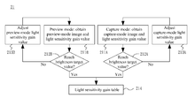
- FIG. 2B shows a detailed flow diagram of the exposure step 21 of FIG. 2A .
- the operating center 16 performs an image capture step 211 A in the capture mode according to a predetermined light sensitivity and the predetermined time, thereby obtaining a capture-mode image and a capture-mode light sensitivity gain value.
- step 212 A it is determined whether the capture-mode image reaches a capture-mode brightness target value.
- step 213 A in which the capture-mode light sensitivity gain value is adjusted, and the image capture step 211 A in the capture mode is repeated until it is determined in step 212 A that the capture-mode image has reached the capture-mode brightness target value. If it is determined in step 212 A that the brightness target value has been reached, the embodiment further includes step 214 , in which the corresponding capture-mode light sensitivity gain value is recorded in a light sensitivity gain table.
- the operating center 16 before or after steps 211 A- 213 A in the capture mode, the operating center 16 performs an image capture step 211 B in the preview mode according to a predetermined light sensitivity and the predetermined time, thereby obtaining a preview-mode image and a preview-mode light sensitivity gain value. Subsequently, in step 212 B, it is determined whether the preview-mode image reaches a preview-mode brightness target value.
- step 213 B in which the preview-mode light sensitivity gain value is adjusted, and the image capture step 211 B in the preview mode is repeated until it is determined in step 212 B that the preview-mode image has reached the preview-mode brightness target value. If it is determined in step 212 B that the brightness target value has been reached, the embodiment further includes step 214 , in which the corresponding preview-mode light sensitivity gain value is recorded in the light sensitivity gain table.
- the exposure step 21 is performed respectively in the capture mode and the preview mode, and the operating center 16 constructs the light sensitivity gain table according to the capture-mode light sensitivity gain value obtained in steps 211 A- 213 A in the capture mode and the preview-mode light sensitivity gain value obtained in steps 211 B- 213 B in the preview mode.
- FIG. 2C shows a detailed flow diagram of the time adjustment step 22 of FIG. 2A .
- the operating center 16 obtains a capture-mode image and a preview-mode image according to the light sensitivity provided from step 21 .
- step 222 it is determined whether an absolute brightness difference between the brightness of the capture-mode image and the brightness of the preview-mode image is less than a threshold. If it is determined that the absolute brightness difference is not less than the threshold, the flow proceeds to step 223 , in which the lag time of the mechanical shutter 14 is adjusted, followed by repeating step 221 . If it is determined in step 222 that the absolute brightness difference is less than the threshold, the current lag time of the mechanical shutter 14 is the desired adjusted time.
Landscapes
- Engineering & Computer Science (AREA)
- Multimedia (AREA)
- Signal Processing (AREA)
- Studio Devices (AREA)
Abstract
Description
Claims (18)
Applications Claiming Priority (2)
| Application Number | Priority Date | Filing Date | Title |
|---|---|---|---|
| TW100104875A TWI433534B (en) | 2011-02-15 | 2011-02-15 | Light sensitivity calibration method and an imaging device |
| TW100104875 | 2011-02-15 |
Publications (2)
| Publication Number | Publication Date |
|---|---|
| US20120206621A1 US20120206621A1 (en) | 2012-08-16 |
| US8780261B2 true US8780261B2 (en) | 2014-07-15 |
Family
ID=46636634
Family Applications (1)
| Application Number | Title | Priority Date | Filing Date |
|---|---|---|---|
| US13/210,859 Active 2032-06-12 US8780261B2 (en) | 2011-02-15 | 2011-08-16 | Light sensitivity calibration method and an imaging device |
Country Status (2)
| Country | Link |
|---|---|
| US (1) | US8780261B2 (en) |
| TW (1) | TWI433534B (en) |
Families Citing this family (19)
| Publication number | Priority date | Publication date | Assignee | Title |
|---|---|---|---|---|
| US10009536B2 (en) | 2016-06-12 | 2018-06-26 | Apple Inc. | Applying a simulated optical effect based on data received from multiple camera sensors |
| DK180859B1 (en) | 2017-06-04 | 2022-05-23 | Apple Inc | USER INTERFACE CAMERA EFFECTS |
| US11112964B2 (en) | 2018-02-09 | 2021-09-07 | Apple Inc. | Media capture lock affordance for graphical user interface |
| US11722764B2 (en) | 2018-05-07 | 2023-08-08 | Apple Inc. | Creative camera |
| DK201870623A1 (en) | 2018-09-11 | 2020-04-15 | Apple Inc. | USER INTERFACES FOR SIMULATED DEPTH EFFECTS |
| US11321857B2 (en) | 2018-09-28 | 2022-05-03 | Apple Inc. | Displaying and editing images with depth information |
| US11128792B2 (en) | 2018-09-28 | 2021-09-21 | Apple Inc. | Capturing and displaying images with multiple focal planes |
| US10645294B1 (en) | 2019-05-06 | 2020-05-05 | Apple Inc. | User interfaces for capturing and managing visual media |
| US11706521B2 (en) | 2019-05-06 | 2023-07-18 | Apple Inc. | User interfaces for capturing and managing visual media |
| US11770601B2 (en) | 2019-05-06 | 2023-09-26 | Apple Inc. | User interfaces for capturing and managing visual media |
| US11054973B1 (en) | 2020-06-01 | 2021-07-06 | Apple Inc. | User interfaces for managing media |
| US11212449B1 (en) * | 2020-09-25 | 2021-12-28 | Apple Inc. | User interfaces for media capture and management |
| US11539876B2 (en) | 2021-04-30 | 2022-12-27 | Apple Inc. | User interfaces for altering visual media |
| US11778339B2 (en) | 2021-04-30 | 2023-10-03 | Apple Inc. | User interfaces for altering visual media |
| US12112024B2 (en) | 2021-06-01 | 2024-10-08 | Apple Inc. | User interfaces for managing media styles |
| CN115484384B (en) * | 2021-09-13 | 2023-12-01 | 华为技术有限公司 | Method and device for controlling exposure and electronic equipment |
| US12506953B2 (en) | 2021-12-03 | 2025-12-23 | Apple Inc. | Device, methods, and graphical user interfaces for capturing and displaying media |
| US20240373121A1 (en) | 2023-05-05 | 2024-11-07 | Apple Inc. | User interfaces for controlling media capture settings |
| US12602154B2 (en) | 2024-01-18 | 2026-04-14 | Apple Inc. | User interfaces integrating hardware buttons |
Citations (12)
| Publication number | Priority date | Publication date | Assignee | Title |
|---|---|---|---|---|
| TW200740211A (en) | 2006-03-09 | 2007-10-16 | Fujifilm Corp | Imaging apparatus and exposure control method |
| US20090268083A1 (en) * | 2007-06-18 | 2009-10-29 | Canon Kabushiki Kaisha | Imaging system, image sensor, and method of controlling imaging system |
| US20100201847A1 (en) * | 2009-02-12 | 2010-08-12 | Samsung Digital Imaging Co., Ltd. | Digital image processing apparatus and method of controlling the same |
| CN101009760B (en) | 2005-08-26 | 2010-09-01 | 索尼株式会社 | Exposure control method, exposure control device and image pickup device |
| TW201101819A (en) | 2009-06-26 | 2011-01-01 | Altek Corp | Digital image special effect treatment method |
| US20110043647A1 (en) * | 2009-08-24 | 2011-02-24 | Samsung Electronics Co., Ltd. | Method and apparatus for determining shaken image by using auto focusing |
| US20110069194A1 (en) * | 2009-09-24 | 2011-03-24 | Canon Kabushiki Kaisha | Imaging apparatus and imaging method |
| US20110293259A1 (en) * | 2010-05-25 | 2011-12-01 | Apple Inc. | Scene Adaptive Auto Exposure |
| US20110298886A1 (en) * | 2010-06-06 | 2011-12-08 | Apple, Inc. | Auto Exposure Techniques for Variable Lighting Conditions |
| US8115859B2 (en) * | 2008-12-01 | 2012-02-14 | Samsung Electro-Mechanics Co., Ltd. | Method for controlling auto-exposure |
| US20120057073A1 (en) * | 2010-06-04 | 2012-03-08 | Apple Inc. | Scene-Aware Automatic-Exposure Control |
| US20120062754A1 (en) * | 2010-09-10 | 2012-03-15 | Altek Corporation | Method for adjusting shooting parameters of digital camera |
-
2011
- 2011-02-15 TW TW100104875A patent/TWI433534B/en active
- 2011-08-16 US US13/210,859 patent/US8780261B2/en active Active
Patent Citations (12)
| Publication number | Priority date | Publication date | Assignee | Title |
|---|---|---|---|---|
| CN101009760B (en) | 2005-08-26 | 2010-09-01 | 索尼株式会社 | Exposure control method, exposure control device and image pickup device |
| TW200740211A (en) | 2006-03-09 | 2007-10-16 | Fujifilm Corp | Imaging apparatus and exposure control method |
| US20090268083A1 (en) * | 2007-06-18 | 2009-10-29 | Canon Kabushiki Kaisha | Imaging system, image sensor, and method of controlling imaging system |
| US8115859B2 (en) * | 2008-12-01 | 2012-02-14 | Samsung Electro-Mechanics Co., Ltd. | Method for controlling auto-exposure |
| US20100201847A1 (en) * | 2009-02-12 | 2010-08-12 | Samsung Digital Imaging Co., Ltd. | Digital image processing apparatus and method of controlling the same |
| TW201101819A (en) | 2009-06-26 | 2011-01-01 | Altek Corp | Digital image special effect treatment method |
| US20110043647A1 (en) * | 2009-08-24 | 2011-02-24 | Samsung Electronics Co., Ltd. | Method and apparatus for determining shaken image by using auto focusing |
| US20110069194A1 (en) * | 2009-09-24 | 2011-03-24 | Canon Kabushiki Kaisha | Imaging apparatus and imaging method |
| US20110293259A1 (en) * | 2010-05-25 | 2011-12-01 | Apple Inc. | Scene Adaptive Auto Exposure |
| US20120057073A1 (en) * | 2010-06-04 | 2012-03-08 | Apple Inc. | Scene-Aware Automatic-Exposure Control |
| US20110298886A1 (en) * | 2010-06-06 | 2011-12-08 | Apple, Inc. | Auto Exposure Techniques for Variable Lighting Conditions |
| US20120062754A1 (en) * | 2010-09-10 | 2012-03-15 | Altek Corporation | Method for adjusting shooting parameters of digital camera |
Also Published As
| Publication number | Publication date |
|---|---|
| US20120206621A1 (en) | 2012-08-16 |
| TW201234847A (en) | 2012-08-16 |
| TWI433534B (en) | 2014-04-01 |
Similar Documents
| Publication | Publication Date | Title |
|---|---|---|
| US8780261B2 (en) | Light sensitivity calibration method and an imaging device | |
| US8638373B2 (en) | Imaging device that resets an exposure by feedback control, method for controlling imaging device and program product | |
| US9554059B1 (en) | Exposure control system and associated exposure control method | |
| US9131197B2 (en) | Imaging apparatus capable of controlling exposure including flash amount control of flash apparatus, and control method thereof | |
| JP5425119B2 (en) | Lens device calibration | |
| US9247150B2 (en) | Image capturing apparatus, exposure control method, and computer-readable recording medium | |
| JP5759190B2 (en) | Imaging apparatus and control method thereof | |
| US9338358B2 (en) | Image capture apparatus and control method for reflecting exposure compensation | |
| US20050264682A1 (en) | Exposure control apparatus and exposure control method | |
| CN104221364A (en) | Imaging device and image processing method | |
| US10425602B2 (en) | Image processing apparatus, image processing method, and computer-readable recording medium | |
| US11438519B2 (en) | Method of fast estimation of scene brightness and optimal camera exposure | |
| JP2008205635A (en) | Imaging device | |
| US9282243B2 (en) | Exposure parameter compensation method and an imaging device | |
| US8488020B2 (en) | Imaging device, method for controlling the imaging device, and recording medium recording the method | |
| JP5167222B2 (en) | White balance adjustment system for solid-state electronic imaging device and operation control method thereof | |
| JP2012095219A (en) | Imaging apparatus and control method of the same | |
| JP4813839B2 (en) | Exposure control method and imaging apparatus | |
| CN102645816B (en) | Exposure parameter correction method and imaging device | |
| JP5587045B2 (en) | Imaging apparatus and control method thereof | |
| CN101273621A (en) | Internal storage of camera characteristics during production | |
| JP6272006B2 (en) | Imaging apparatus, image processing method, and program | |
| JP7464557B2 (en) | Surveillance camera, surveillance camera system, and surveillance camera calibration method | |
| CN102647551B (en) | Sensitivity correction method and imaging device | |
| JP5595159B2 (en) | Imaging apparatus and control method thereof |
Legal Events
| Date | Code | Title | Description |
|---|---|---|---|
| AS | Assignment |
Owner name: ABILITY ENTERPRISE CO., LTD., TAIWAN Free format text: ASSIGNMENT OF ASSIGNORS INTEREST;ASSIGNORS:CHEN, TAI-HUNG;TSAI, YI-WEN;LEE, YIJIAN;REEL/FRAME:026758/0900 Effective date: 20110804 |
|
| STCF | Information on status: patent grant |
Free format text: PATENTED CASE |
|
| MAFP | Maintenance fee payment |
Free format text: PAYMENT OF MAINTENANCE FEE, 4TH YEAR, LARGE ENTITY (ORIGINAL EVENT CODE: M1551) Year of fee payment: 4 |
|
| MAFP | Maintenance fee payment |
Free format text: PAYMENT OF MAINTENANCE FEE, 8TH YEAR, LARGE ENTITY (ORIGINAL EVENT CODE: M1552); ENTITY STATUS OF PATENT OWNER: LARGE ENTITY Year of fee payment: 8 |
|
| MAFP | Maintenance fee payment |
Free format text: PAYMENT OF MAINTENANCE FEE, 12TH YEAR, LARGE ENTITY (ORIGINAL EVENT CODE: M1553); ENTITY STATUS OF PATENT OWNER: LARGE ENTITY Year of fee payment: 12 |