US8778006B2 - Delivery system having a release mechanism for releasing an object carried by a catheter as well as a release mechanism of a delivery system - Google Patents
Delivery system having a release mechanism for releasing an object carried by a catheter as well as a release mechanism of a delivery system Download PDFInfo
- Publication number
- US8778006B2 US8778006B2 US12/430,191 US43019109A US8778006B2 US 8778006 B2 US8778006 B2 US 8778006B2 US 43019109 A US43019109 A US 43019109A US 8778006 B2 US8778006 B2 US 8778006B2
- Authority
- US
- United States
- Prior art keywords
- outer shaft
- catheter
- delivery system
- brake
- roller
- Prior art date
- Legal status (The legal status is an assumption and is not a legal conclusion. Google has not performed a legal analysis and makes no representation as to the accuracy of the status listed.)
- Active, expires
Links
Images


Classifications
-
- A—HUMAN NECESSITIES
- A61—MEDICAL OR VETERINARY SCIENCE; HYGIENE
- A61F—FILTERS IMPLANTABLE INTO BLOOD VESSELS; PROSTHESES; DEVICES PROVIDING PATENCY TO, OR PREVENTING COLLAPSING OF, TUBULAR STRUCTURES OF THE BODY, e.g. STENTS; ORTHOPAEDIC, NURSING OR CONTRACEPTIVE DEVICES; FOMENTATION; TREATMENT OR PROTECTION OF EYES OR EARS; BANDAGES, DRESSINGS OR ABSORBENT PADS; FIRST-AID KITS
- A61F2/00—Filters implantable into blood vessels; Prostheses, i.e. artificial substitutes or replacements for parts of the body; Appliances for connecting them with the body; Devices providing patency to, or preventing collapsing of, tubular structures of the body, e.g. stents
- A61F2/95—Instruments specially adapted for placement or removal of stents or stent-grafts
- A61F2/9517—Instruments specially adapted for placement or removal of stents or stent-grafts handle assemblies therefor
-
- A—HUMAN NECESSITIES
- A61—MEDICAL OR VETERINARY SCIENCE; HYGIENE
- A61F—FILTERS IMPLANTABLE INTO BLOOD VESSELS; PROSTHESES; DEVICES PROVIDING PATENCY TO, OR PREVENTING COLLAPSING OF, TUBULAR STRUCTURES OF THE BODY, e.g. STENTS; ORTHOPAEDIC, NURSING OR CONTRACEPTIVE DEVICES; FOMENTATION; TREATMENT OR PROTECTION OF EYES OR EARS; BANDAGES, DRESSINGS OR ABSORBENT PADS; FIRST-AID KITS
- A61F2/00—Filters implantable into blood vessels; Prostheses, i.e. artificial substitutes or replacements for parts of the body; Appliances for connecting them with the body; Devices providing patency to, or preventing collapsing of, tubular structures of the body, e.g. stents
- A61F2/95—Instruments specially adapted for placement or removal of stents or stent-grafts
- A61F2/962—Instruments specially adapted for placement or removal of stents or stent-grafts having an outer sleeve
- A61F2/966—Instruments specially adapted for placement or removal of stents or stent-grafts having an outer sleeve with relative longitudinal movement between outer sleeve and prosthesis, e.g. using a push rod
-
- A—HUMAN NECESSITIES
- A61—MEDICAL OR VETERINARY SCIENCE; HYGIENE
- A61F—FILTERS IMPLANTABLE INTO BLOOD VESSELS; PROSTHESES; DEVICES PROVIDING PATENCY TO, OR PREVENTING COLLAPSING OF, TUBULAR STRUCTURES OF THE BODY, e.g. STENTS; ORTHOPAEDIC, NURSING OR CONTRACEPTIVE DEVICES; FOMENTATION; TREATMENT OR PROTECTION OF EYES OR EARS; BANDAGES, DRESSINGS OR ABSORBENT PADS; FIRST-AID KITS
- A61F2/00—Filters implantable into blood vessels; Prostheses, i.e. artificial substitutes or replacements for parts of the body; Appliances for connecting them with the body; Devices providing patency to, or preventing collapsing of, tubular structures of the body, e.g. stents
- A61F2/95—Instruments specially adapted for placement or removal of stents or stent-grafts
- A61F2/962—Instruments specially adapted for placement or removal of stents or stent-grafts having an outer sleeve
- A61F2/97—Instruments specially adapted for placement or removal of stents or stent-grafts having an outer sleeve the outer sleeve being splittable
-
- A61F2002/9517—
Definitions
- the present disclosure relates to a delivery system having a release mechanism for releasing an object carried by a catheter.
- the present disclosure also relates to a release mechanism of a delivery system.
- catheters may be used for releasing objects, e.g., stents, or for use of dilatation balloons.
- objects e.g., stents
- dilatation balloons One field of application is in angioplasty, for example, where balloon catheters are inserted into blood vessels and advanced up to a stenosis, where the balloon catheters are dilated to eliminate the stenosis of the blood vessel.
- a small-diameter guide wire usually protrudes beyond the balloon catheter at the distal end.
- German Patent Application No. 600 11 355 discloses a delivery system for an intravascular prosthesis with which the proximal end of a catheter engages in a running device which facilitates a relative displacement between an inner sheath and an outer sheath of the catheter. For releasing an object such as a stent arranged on the distal end, the outer sheath is pulled toward the proximal end. This movement may take place uniformly by pulling the outer sheath into the running device.
- One aspect of the present disclosure provides a delivery system having a release mechanism for releasing an object which is carried by a catheter, whereby the catheter has at least one outer shaft displaceable relatively toward the object to release said object, wherein the catheter, on its proximal end ( 24 ), has a winding device which winds up a proximal section of the outer shaft to create a relative displacement of the outer shaft.
- a further aspect of the present disclosure provides a delivery system for releasing an object carried by a catheter, the delivery system comprising a) a catheter having a proximal end, a distal end and at least one displaceable outer shaft having a proximal section; b) a release mechanism for releasing an object carried by the catheter; and, c) a winding device associated with the proximal end of the outer shaft, the winding device being capable of winding up the proximal section of the outer shaft so as to create a relative displacement of the outer shaft.
- the present disclosure provides a delivery system having a release mechanism for an object to be released as well as a release device of a delivery system which permits easy and ergonomic handling.
- the present disclosure provides a delivery system having a release mechanism for releasing an object, in particular, a stent body, which is carried by a catheter, such that the catheter has at least one outer shaft which is displaceable relatively toward the object to release it.
- the catheter shall have a winding device on its proximal end to wind up a proximal section of the outer shaft to create a relative displacement of the outer shaft.
- the winding induces a sliding movement in the outer shaft which moves the outer shaft away from the distal end of the catheter to the proximal end.
- the sliding movement may take place in a controlled and precise manner.
- the winding allows a compact design of the catheter with a length that is independent of the length of the object to be released, e.g., a stent.
- the winding device can relieve the burden on the user and can at least partially assume the propulsion force for retraction of the outer shaft in releasing the object. The release may take place in a very controlled and accurate manner.
- the displacement of the outer shaft may proceed continuously and uniformly. It is likewise conceivable that a variable displacement rate can be implemented manually or with automation to retract the outer shaft more slowly at the start of its release and retract it more rapidly toward the end of its release.
- the release mechanism preferably has a cutting device which can cut the section of the outer shaft that is moved toward the proximal end of the catheter.
- the cutting device may preferably have at least one cutting blade which cuts the outer shaft in the axial direction. By cutting the outer shaft, the free end of the outer shaft may be gripped in the winding mechanism and wound up. This makes it possible to avoid having to design the catheter to be longer, e.g., in supporting bodies such as stents having a longitudinal extent greater than is the case with shorter supporting bodies to guarantee a more reliable release of the stent body.
- the catheter may be designed independently of the length of the supporting body. In the manufacture of catheters for different objects, such as stents, to be released, inexpensive identical parts may be used.
- the release mechanism may advantageously form a handle part of the catheter. This allows especially ergonomic handling of the catheter. Likewise, the release mechanism may form a T-shaped body as an end piece of the catheter.
- the winding mechanism may preferably comprise a roller arranged at one end of the catheter.
- a cut may be formed in the outer shaft, and the cut shaft lateral surface may be wound up by the winding mechanism.
- the winding mechanism may comprise at least two rollers arranged, preferably symmetrically, on the catheter. At least two cuts can be produced here and the cut section of the outer shaft may be divided into separate surface areas, each being gripped and wound up separately by the winding mechanism. This facilitates the winding, which can be performed with little expenditure of force.
- the present disclosure relates to a release mechanism for a delivery system for releasing an object, in particular, a stent body, which is carried by a catheter on its distal end, whereby the catheter has at least one outer shaft which is displaceable relative to the object to thereby release the object.
- a winding device which winds a proximal section of the outer shaft to produce a relative displacement of the outer shaft.
- the winding induces a sliding movement in the outer shaft away from the distal end of the catheter toward the proximal end.
- the sliding movement may take place in a controlled and precise manner.
- the object may be released in a very controlled and accurate manner because the small dimension of the handling part advantageously allows optimum handling.
- the displacement of the outer shaft may take place continuously and uniformly. It is likewise conceivable for a variable displacement rate to be manually implementable or automated so as to retract the outer shaft more slowly at the start of its release for more accurate positioning of the outer shaft and more rapidly toward the end of its release.
- the winding device may advantageously be connected to a conventional catheter.
- a cutting device may preferably be connected to the winding device so that the section of the outer shaft moved toward the proximal end of the catheter can be cut when the outer shaft is moved toward the proximal end to release the object on the distal end of the catheter.
- At least one roller may be provided in the winding device so that the outer shaft can be wound onto the roller in at least some areas.
- the outer shaft may be moved at a variable rate with a constant rotational speed.
- the at least one roller can be locked by a locking mechanism. This allows a defined start of the release and good control of the movement of the outer shaft, which can also be interrupted in a controlled manner.
- the winding device for rolling up the shaft may advantageously be connected to a spring element so that the winding and/or the movement of the outer shaft can be supported by the spring force. This allows especially simple and controlled handling of the winding device.
- the winding device for winding up the outer shaft may be drivable by hand, e.g., with a crank element.
- the winding device may alternatively or additionally comprise an electric drive for winding up the outer shaft.
- the winding of the outer shaft may take place in this way without application of force by the user.
- the winding device may have an operating element which, in a first position, releases the at least one roller for execution of a rotational movement and, in another position, blocks the at least one roller.
- a defined and controlled movement of the outer shaft may advantageously be achieved in this way.
- FIG. 1 shows a first exemplary embodiment having a winding device for winding up a cut outer shaft to release a stent at a distal end of a catheter;
- FIG. 2 shows a detail of the exemplary embodiment shown in FIG. 1 ;
- FIG. 3 shows a second exemplary embodiment having an outer shaft cut at one end
- FIG. 4 a shows a detailed side view of two cooperating rollers of a preferred winding device
- FIG. 4 b shows a detailed top view of two cooperating rollers of a preferred winding device
- FIG. 5 shows a top view of a delivery system with a preferred winding device
- FIG. 6 shows a side view of the delivery system shown in FIG. 5 without the housing and winding device
- FIG. 7 a shows an exemplary embodiment of a delivery system with rollers oriented differently with respect to a catheter
- FIG. 7 b shows an exemplary embodiment of a preferred delivery system with rollers oriented with respect to a catheter
- FIG. 8 a shows a third exemplary embodiment of a preferred delivery system with rollers oriented in relation to a catheter
- FIG. 8 b shows a fourth exemplary embodiment of a delivery system with rollers oriented in relation to a catheter
- FIG. 9 shows an exemplary embodiment of a roller of a winding device
- FIG. 10 a shows a release mechanism of a winding device with a roller
- FIG. 10 b shows a detail of the release mechanism shown in FIG. 10 a.
- FIG. 1 shows a first exemplary embodiment of the present disclosure having a first delivery system 10 with a release mechanism 70 for releasing an object 12 , in particular, a supporting body carried on a distal end 22 of a catheter 20 , such that the catheter 20 has at least one outer shaft 50 which is relatively displaceable toward the object 12 to release the object 12 in a pulling direction 68 .
- the catheter 20 has a winding device 100 on its proximal end 24 which winds a proximal section 52 of the outer shaft 50 to create the relative displacement of the outer shaft 50 .
- the proximal section 52 of the outer shaft 50 corresponds to the length of the object 12 , which may be a self-expanding stent, for example.
- the terms “proximal” and “distal” refer to the position of the user, so the proximal end 24 is near the user, while the distal end 22 is remote from the user.
- the outer shaft 50 is arranged around an inner shaft 28 , with a tip 30 being provided on the distal end 22 of the catheter 20 for guiding the catheter 20 over a guide wire in the usual manner, such that the object 12 surrounds the inner shaft 28 and is adapted for insertion into a blood vessel, for example, within the outer shaft 50 .
- the winding device 100 comprises two rollers 104 a , 104 b which are arranged symmetrically with the catheter 20 and/or the outer shaft 50 and can be driven by a drive (not shown here), e.g., a crank or an electric motor.
- a drive e.g., a crank or an electric motor.
- the releasing mechanism 70 comprises, in addition to the winding device 100 , a cutting device 120 having at least one cutting blade 122 with which the section 52 of the outer shaft 50 that is moved toward the proximal end 24 of the catheter 20 can be cut along the longitudinal extent 72 of the outer shaft 50 .
- a symmetrical separation of the outer shaft 50 into two parts 60 a, 60 b is expedient.
- the outer shaft 50 may be cut on the proximal end of the catheter 20 and its ends attached to the rollers 104 a, 104 b.
- the rollers 104 a, 104 b are rotated, the parts 60 a, 60 b are placed on a lateral surface 113 a (roller 104 a ) and/or 113 b (roller 104 b ) of the rollers 104 a, 104 b and secured at the ends 66 a, 66 b, which is shown more clearly in the detail in FIG. 2 .
- Rollers 104 a, 104 b are rotated in the opposite direction of rotation 110 , 112 .
- roller 104 a rotates counterclockwise and roller 104 b rotates clockwise.
- the rotation may be accomplished with a drive 74 , e.g., by a hand-operated crank or an electrically operated drive (not shown).
- gearwheel 108 a, 108 b is arranged on one end of each roller 104 a , 104 b.
- the gearwheels 108 a, 108 b intermesh so that the movement of one roller, e.g., 104 b , induces movement of the other roller, e.g., 104 a, and symmetrical winding is possible ( FIGS. 4 a and 4 b ).
- FIG. 3 shows another exemplary embodiment of the present disclosure in which, instead of making several cuts in the outer shaft 50 , only a one-sided cut 54 is made from a proximal free end 66 of the outer shaft 50 up to a stop element 58 along the longitudinal extent 72 of the catheter 20 .
- the winding device (not shown here) then preferably has only a single roller for winding up the outer shaft 50 , as explained in greater detail in the exemplary embodiment in FIGS. 7 a and 7 b.
- FIG. 5 shows a preferred release mechanism 70 having two rollers 104 a, 104 b in a housing 86 as seen from above
- FIG. 6 shows an end body 80 of the catheter 20 in a side view with the housing 86 having the release mechanism 70 arranged thereon (the housing and winding device are not shown in the side view in FIG. 6 ).
- the end body 80 may also be integrated into the housing 86 of the release mechanism 70 .
- the rollers 104 a, 104 b are situated symmetrically with one another and rotate in opposite directions when operated.
- the rollers 104 a, 104 b may be secured or released with a locking mechanism 118 on one of the rollers 104 b.
- the inner shaft 28 of the catheter 20 ( FIG. 1 ) may be secured, for example, by means of a metal shaft 88 ( FIGS. 6 , 8 a and 8 b ) in the housing 86 .
- a kink guard 26 sheathing the catheter 20 is provided on the catheter 20 adjacent to the housing 86 .
- a connection 82 e.g., in the form of a Luer lock, serves to provide a conventional rinsing of the space between the inner shaft 28 and outer shaft 50 .
- a connection 84 on the free end is optionally also designed as a Luer lock and serves to insert a guide wire and to rinse this area.
- two symmetrically positioned cutting blades 122 are arranged on a shoulder 124 of the end body 80 to cut the outer shaft 50 from the inside out in retraction.
- An arrangement in which the outer shaft 50 is cut longitudinally with exterior cutting blades (not shown) would also be conceivable.
- seals 96 and 98 are arranged at each end of the end body 80 to seal the space between the inner shaft 28 and the outer shaft 50 and/or the metal shaft 88 and the end body 80 and/or outer shaft 50 .
- the outer shaft 50 which is already partially slotted, is attached to the rollers 104 a , 104 b at the lateral surfaces 113 a, 113 b for winding, as indicated in FIGS. 1 and 2 .
- the outer shaft 50 is wound up and automatically retracted toward the proximal end 24 of the catheter 20 .
- the object 12 ( FIG. 1 ), e.g., a self-expanding stent, is thereby released.
- FIGS. 7 a and 7 b illustrate schematically additional preferred exemplary embodiments of a delivery system 10 having a release mechanism 70 comprising a winding device 100 which has only one roller 102 and comprises a one-sided cutting device, as diagrammed schematically in FIG. 3 .
- the roller 102 is arranged on the catheter 20 at one end.
- the release mechanism 70 is integrated into an end body 80 of the catheter 20 and forms a handle part of the catheter 20 , having a handle area 94 which the user can hold in his hand.
- the roller 102 may be rotated either clockwise or counterclockwise such that rotation in only one direction is allowed for the user and rotation in the opposite direction is blocked.
- the catheter 20 is provided with a kink guard 26 on the outside circumference, protrudes into the end body 80 and may be attached with a metal shaft on the end body 80 as described hereinabove.
- FIG. 7 a shows an exemplary embodiment in which the roller 102 of the winding device 100 is upended so that the roller 102 stands with its circular surface next to and parallel to the catheter 20 .
- FIG. 7 b shows a second exemplary embodiment in which the catheter 20 is arranged tangentially to the roller 102 .
- the cutting device is not shown explicitly.
- the roller 102 can be secured with a locking mechanism 118 designed as a slide that can move back and forth, for example, and is secured or released as indicated by a double arrow.
- Roller 102 is arranged distally from the handle area 94 of the end body 80 .
- the user holding the end part by the handle area 94 will rotate the roller 102 , e.g., with his thumbs, thus allowing one-handed operation of the release mechanism 70 and/or the winding device 100 of the delivery system 10 .
- the cutting can be stopped with a stop element 58 ( FIGS. 1 , 2 and 3 ) or by allowing only a limited number of revolutions of the roller 102 .
- FIGS. 8 a and 8 b show another exemplary embodiment of the present disclosure with an end body 80 designed as a T-shaped body in which the roller 102 is arranged tangentially to the winding device 100 ( FIG. 8 a ) or parallel and next to the catheter 20 and/or the end body 80 ( FIG. 8 b ).
- rollers 102 , 104 a, 104 b may have a cylindrical lateral surface 113 or a tapered conical shape, as illustrated in FIG. 9 .
- the roller 102 , 104 a, 104 b has a larger diameter of the lateral surface 113 than on its opposing axial end 116 .
- the parts 60 , 60 a , 60 b of the outer shaft 50 are wound up at different rates at a constant rotational speed of the roller 102 , 104 a, 104 b, depending on the axial height at which the parts 60 , 60 a, 60 b are deposited.
- the shaft may be wound onto the thinner end of the roller 102 , 104 a, 104 b, so that the outer shaft 50 is retracted at a lower rate.
- the shaft is wound onto the thicker end of the roller 102 , 104 a, 104 b, which causes a faster movement of the outer shaft 50 .
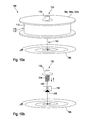
- FIGS. 10 a and 10 b show a detail of a winding device 100 in which the roller 102 , 104 a, 104 b can be rotated mechanically or electrically with a release mechanism 130 .
- the release mechanism extends along a central axis 140 of the roller 102 , 104 a, 104 b.
- An operating element 132 may be moved outward against the spring force of a spring element 134 , which is designed as an axial spring, for example. Through this movement, a mating element 138 is moved out of a brake 136 and the axle 140 is thus released.
- the brake 136 may comprise brake shoes, for example, with which the mating element 138 engages when the roller 102 , 104 a, 104 b is blocked.
- the axle 140 is connected to a spring element 106 , which is designed as a rotary spring and can induce a rotational movement in the axle 140 and thus in the rollers 102 , 104 a, 104 b when the mating element 138 is uncoupled from the brake 136 .
- An electric drive may also be provided instead of the spring element 106 .
- the reel 102 , 104 a, 104 b may be operated by pushbutton and offers the possibility of achieving different winding speeds. For example, cutting can be stopped by allowing only a limited number of revolutions of the rollers 102 , 104 a, 104 b and/or allowing only a limited movement of the spring element 106 .
Landscapes
- Health & Medical Sciences (AREA)
- Engineering & Computer Science (AREA)
- Biomedical Technology (AREA)
- Cardiology (AREA)
- Oral & Maxillofacial Surgery (AREA)
- Transplantation (AREA)
- Heart & Thoracic Surgery (AREA)
- Vascular Medicine (AREA)
- Life Sciences & Earth Sciences (AREA)
- Animal Behavior & Ethology (AREA)
- General Health & Medical Sciences (AREA)
- Public Health (AREA)
- Veterinary Medicine (AREA)
- Media Introduction/Drainage Providing Device (AREA)
Abstract
Description
Claims (20)
Applications Claiming Priority (3)
| Application Number | Priority Date | Filing Date | Title |
|---|---|---|---|
| DE102008021060.9 | 2008-04-26 | ||
| DE102008021060 | 2008-04-26 | ||
| DE102008021060A DE102008021060A1 (en) | 2008-04-26 | 2008-04-26 | An insertion device with a release device for releasing an article carried by a catheter and a release device of an insertion device |
Publications (2)
| Publication Number | Publication Date |
|---|---|
| US20090270969A1 US20090270969A1 (en) | 2009-10-29 |
| US8778006B2 true US8778006B2 (en) | 2014-07-15 |
Family
ID=40845886
Family Applications (1)
| Application Number | Title | Priority Date | Filing Date |
|---|---|---|---|
| US12/430,191 Active 2031-02-28 US8778006B2 (en) | 2008-04-26 | 2009-04-27 | Delivery system having a release mechanism for releasing an object carried by a catheter as well as a release mechanism of a delivery system |
Country Status (3)
| Country | Link |
|---|---|
| US (1) | US8778006B2 (en) |
| EP (1) | EP2111826B1 (en) |
| DE (1) | DE102008021060A1 (en) |
Cited By (8)
| Publication number | Priority date | Publication date | Assignee | Title |
|---|---|---|---|---|
| US20120259355A1 (en) * | 2011-04-08 | 2012-10-11 | Kyphon Sarl | Retractable inflatable bone tamp |
| US10299949B2 (en) | 2014-02-25 | 2019-05-28 | Biotronik Ag | Release device for releasing a medical implant from a catheter, and catheter |
| US10441449B1 (en) | 2018-05-30 | 2019-10-15 | Vesper Medical, Inc. | Rotary handle stent delivery system and method |
| US10449073B1 (en) | 2018-09-18 | 2019-10-22 | Vesper Medical, Inc. | Rotary handle stent delivery system and method |
| US11219541B2 (en) | 2020-05-21 | 2022-01-11 | Vesper Medical, Inc. | Wheel lock for thumbwheel actuated device |
| US11712330B2 (en) | 2019-07-03 | 2023-08-01 | Aquedeon Medical, Inc. | Vascular and aortic grafts and deployment tools |
| US12029639B2 (en) | 2018-07-03 | 2024-07-09 | Aquedeon Medical, Inc. | Vascular and aortic grafts and deployment tool |
| US12403024B2 (en) | 2020-03-04 | 2025-09-02 | Aquedeon Medical, Inc. | Vascular and aortic grafts with telescoping sheath and deployment methods thereof |
Families Citing this family (20)
| Publication number | Priority date | Publication date | Assignee | Title |
|---|---|---|---|---|
| EP2419059A1 (en) * | 2009-04-15 | 2012-02-22 | Cook Medical Technologies LLC | Introducer apparatus |
| EP2419060B1 (en) * | 2009-04-15 | 2018-02-28 | Cook Medical Technologies LLC | Everting deployment system and handle |
| EP2623151A4 (en) * | 2010-09-28 | 2014-04-16 | Terumo Corp | Introducer sheath, placement device for blood vessel treatment instrument, and method for shortening introducer sheath |
| US8657866B2 (en) * | 2010-12-22 | 2014-02-25 | Cook Medical Technologies Llc | Emergency vascular repair prosthesis deployment system |
| GB2488107B (en) * | 2011-02-11 | 2013-03-06 | Cook Medical Technologies Llc | Drive assembly for facilitating deployment of an implantable medical device |
| GB2488531B (en) * | 2011-02-18 | 2013-04-10 | Cook Medical Technologies Llc | Introducer and deployment handle for splittable sheath |
| US10213329B2 (en) | 2011-08-12 | 2019-02-26 | W. L. Gore & Associates, Inc. | Evertable sheath devices, systems, and methods |
| US9131959B2 (en) * | 2011-08-22 | 2015-09-15 | Cook Medical Technologies Llc | Splittable dilator delivery system |
| US9849015B2 (en) | 2012-12-28 | 2017-12-26 | Cook Medical Technologies Llc | Endoluminal prosthesis introducer |
| US9907641B2 (en) | 2014-01-10 | 2018-03-06 | W. L. Gore & Associates, Inc. | Implantable intraluminal device |
| US9763819B1 (en) | 2013-03-05 | 2017-09-19 | W. L. Gore & Associates, Inc. | Tapered sleeve |
| US9974676B2 (en) | 2013-08-09 | 2018-05-22 | Cook Medical Technologies Llc | Wire collection device with geared advantage |
| US9974677B2 (en) | 2013-08-20 | 2018-05-22 | Cook Medical Technologies Llc | Wire collection device for stent delivery system |
| US10966850B2 (en) * | 2014-03-06 | 2021-04-06 | W. L. Gore & Associates, Inc. | Implantable medical device constraint and deployment apparatus |
| US9974678B2 (en) | 2014-03-10 | 2018-05-22 | Cook Medical Technologies Llc | Wire collection device with varying collection diameter |
| US10137020B2 (en) * | 2014-12-09 | 2018-11-27 | Cook Medical Technologies Llc | Two pronged handle |
| EP3400914A1 (en) | 2017-05-08 | 2018-11-14 | Biotronik AG | Handle for a catheter and corresponding catheter |
| US20180325585A1 (en) * | 2017-05-15 | 2018-11-15 | Biosense Webster (Israel) Ltd. | Networked thermistors |
| US11241324B2 (en) | 2017-09-13 | 2022-02-08 | CARDINAL HEALTH SWITZERLAND 515 GmbH | Stent delivery catheter with fine thumbwheel control and fast crank handle |
| ES2960532T3 (en) | 2017-10-11 | 2024-03-05 | Gore & Ass | Implantable medical device restraint and deployment apparatus |
Citations (20)
| Publication number | Priority date | Publication date | Assignee | Title |
|---|---|---|---|---|
| US5346498A (en) * | 1991-11-06 | 1994-09-13 | Imagyn Medical, Inc. | Controller for manipulation of instruments within a catheter |
| EP0747021A2 (en) | 1995-06-07 | 1996-12-11 | Cook Incorporated | Stent introducer |
| US5690644A (en) * | 1992-12-30 | 1997-11-25 | Schneider (Usa) Inc. | Apparatus for deploying body implantable stent |
| DE19936207A1 (en) | 1999-08-02 | 2001-02-15 | Angiomed Ag | Catheter and introducer with separator |
| US6533811B1 (en) | 1993-07-08 | 2003-03-18 | Medtronic, Inc. | Internal graft prosthesis and delivery system |
| US6599296B1 (en) * | 2001-07-27 | 2003-07-29 | Advanced Cardiovascular Systems, Inc. | Ratcheting handle for intraluminal catheter systems |
| US6673101B1 (en) * | 2002-10-09 | 2004-01-06 | Endovascular Technologies, Inc. | Apparatus and method for deploying self-expanding stents |
| US20040098083A1 (en) * | 2001-04-11 | 2004-05-20 | Khanh Tran | Multi-length delivery system |
| EP1447058A1 (en) | 1998-09-30 | 2004-08-18 | Bard Peripheral Vascular, Inc. | Delivery mechanism for implantable stent |
| US6866669B2 (en) | 2001-10-12 | 2005-03-15 | Cordis Corporation | Locking handle deployment mechanism for medical device and method |
| US20050080476A1 (en) * | 2003-10-09 | 2005-04-14 | Gunderson Richard C. | Medical device delivery system |
| DE60011355T2 (en) | 1999-08-24 | 2005-07-14 | Novatech Sa | Attachment system for an intravascular prosthesis |
| US20050256562A1 (en) * | 2004-05-14 | 2005-11-17 | Boston Scientific Scimed, Inc. | Stent delivery handle and assembly formed therewith |
| US20060283998A1 (en) * | 2005-06-15 | 2006-12-21 | Daiwa Seiko, Inc. | Electric fishing reel |
| DE102006004123A1 (en) | 2006-01-25 | 2007-08-02 | Jotec Gmbh | Feed system for the insertion of expandable stents into cardiac arteries uses a hand held grip |
| US20070219617A1 (en) * | 2006-03-17 | 2007-09-20 | Sean Saint | Handle for Long Self Expanding Stent |
| EP1844739A1 (en) | 2006-04-13 | 2007-10-17 | Medtronic Vascular, Inc. | Short handle for a long stent |
| US20080091137A1 (en) * | 2006-10-17 | 2008-04-17 | Reavill Matthew D | Apparatus and method of inserting an infusing catheter and determining catheter depth without a guidewire or direct contact with the catheter |
| WO2009091603A1 (en) | 2008-01-15 | 2009-07-23 | Gore Enterprise Holdings, Inc. | Pleated deployment sheath |
| US20100036472A1 (en) * | 2008-08-08 | 2010-02-11 | Abbott Cardiovascular Systems Inc. | Delivery system with variable delivery rate for deploying a medical device |
-
2008
- 2008-04-26 DE DE102008021060A patent/DE102008021060A1/en not_active Withdrawn
-
2009
- 2009-03-26 EP EP09156301A patent/EP2111826B1/en active Active
- 2009-04-27 US US12/430,191 patent/US8778006B2/en active Active
Patent Citations (21)
| Publication number | Priority date | Publication date | Assignee | Title |
|---|---|---|---|---|
| US5346498A (en) * | 1991-11-06 | 1994-09-13 | Imagyn Medical, Inc. | Controller for manipulation of instruments within a catheter |
| US5690644A (en) * | 1992-12-30 | 1997-11-25 | Schneider (Usa) Inc. | Apparatus for deploying body implantable stent |
| US6533811B1 (en) | 1993-07-08 | 2003-03-18 | Medtronic, Inc. | Internal graft prosthesis and delivery system |
| EP0747021A2 (en) | 1995-06-07 | 1996-12-11 | Cook Incorporated | Stent introducer |
| EP1447058A1 (en) | 1998-09-30 | 2004-08-18 | Bard Peripheral Vascular, Inc. | Delivery mechanism for implantable stent |
| DE19936207A1 (en) | 1999-08-02 | 2001-02-15 | Angiomed Ag | Catheter and introducer with separator |
| DE60011355T2 (en) | 1999-08-24 | 2005-07-14 | Novatech Sa | Attachment system for an intravascular prosthesis |
| US20040098083A1 (en) * | 2001-04-11 | 2004-05-20 | Khanh Tran | Multi-length delivery system |
| US6599296B1 (en) * | 2001-07-27 | 2003-07-29 | Advanced Cardiovascular Systems, Inc. | Ratcheting handle for intraluminal catheter systems |
| US6866669B2 (en) | 2001-10-12 | 2005-03-15 | Cordis Corporation | Locking handle deployment mechanism for medical device and method |
| US6673101B1 (en) * | 2002-10-09 | 2004-01-06 | Endovascular Technologies, Inc. | Apparatus and method for deploying self-expanding stents |
| US20050080476A1 (en) * | 2003-10-09 | 2005-04-14 | Gunderson Richard C. | Medical device delivery system |
| US20050256562A1 (en) * | 2004-05-14 | 2005-11-17 | Boston Scientific Scimed, Inc. | Stent delivery handle and assembly formed therewith |
| US20060283998A1 (en) * | 2005-06-15 | 2006-12-21 | Daiwa Seiko, Inc. | Electric fishing reel |
| DE102006004123A1 (en) | 2006-01-25 | 2007-08-02 | Jotec Gmbh | Feed system for the insertion of expandable stents into cardiac arteries uses a hand held grip |
| US20070219617A1 (en) * | 2006-03-17 | 2007-09-20 | Sean Saint | Handle for Long Self Expanding Stent |
| EP1844739A1 (en) | 2006-04-13 | 2007-10-17 | Medtronic Vascular, Inc. | Short handle for a long stent |
| US20070244540A1 (en) * | 2006-04-13 | 2007-10-18 | Medtronic Vascular, Inc., A Delaware Corporation | Short Handle for a Long Stent |
| US20080091137A1 (en) * | 2006-10-17 | 2008-04-17 | Reavill Matthew D | Apparatus and method of inserting an infusing catheter and determining catheter depth without a guidewire or direct contact with the catheter |
| WO2009091603A1 (en) | 2008-01-15 | 2009-07-23 | Gore Enterprise Holdings, Inc. | Pleated deployment sheath |
| US20100036472A1 (en) * | 2008-08-08 | 2010-02-11 | Abbott Cardiovascular Systems Inc. | Delivery system with variable delivery rate for deploying a medical device |
Non-Patent Citations (2)
| Title |
|---|
| Search Report for European Patent Application No. 09156301.5; Aug. 17, 2009. |
| Search Report for German Patent Application No. 10 2008 021 060.9; Mar. 11, 2009. |
Cited By (20)
| Publication number | Priority date | Publication date | Assignee | Title |
|---|---|---|---|---|
| US11006993B2 (en) | 2011-04-08 | 2021-05-18 | Medtronic Holding Company Sarl | Retractable inflatable bone tamp |
| US12016605B2 (en) | 2011-04-08 | 2024-06-25 | Medtronic Holding Company Sarl | Retractable inflatable bone tamp |
| US20120259355A1 (en) * | 2011-04-08 | 2012-10-11 | Kyphon Sarl | Retractable inflatable bone tamp |
| US10299949B2 (en) | 2014-02-25 | 2019-05-28 | Biotronik Ag | Release device for releasing a medical implant from a catheter, and catheter |
| US11234848B2 (en) | 2018-05-30 | 2022-02-01 | Vesper Medical, Inc. | Rotary handle stent delivery system and method |
| US10987239B2 (en) | 2018-05-30 | 2021-04-27 | Vesper Medical, Inc. | Rotary handle stent delivery system and method |
| US10441449B1 (en) | 2018-05-30 | 2019-10-15 | Vesper Medical, Inc. | Rotary handle stent delivery system and method |
| US12029639B2 (en) | 2018-07-03 | 2024-07-09 | Aquedeon Medical, Inc. | Vascular and aortic grafts and deployment tool |
| US11419744B2 (en) | 2018-09-18 | 2022-08-23 | Vesper Medical, Inc. | Rotary sheath withdrawal system and method |
| US10449073B1 (en) | 2018-09-18 | 2019-10-22 | Vesper Medical, Inc. | Rotary handle stent delivery system and method |
| US11160676B2 (en) | 2018-09-18 | 2021-11-02 | Vesper Medical, Inc. | Rotary handle stent delivery system and method |
| US10736762B2 (en) | 2018-09-18 | 2020-08-11 | Vesper Medical, Inc. | Rotary handle stent delivery system and method |
| US10993825B2 (en) | 2018-09-18 | 2021-05-04 | Vesper Medical, Inc. | Rotary handle stent delivery system and method |
| US12115091B2 (en) | 2018-09-18 | 2024-10-15 | Vesper Medical, Inc. | Rotary sheath withdrawal system and method |
| US11712330B2 (en) | 2019-07-03 | 2023-08-01 | Aquedeon Medical, Inc. | Vascular and aortic grafts and deployment tools |
| US11864977B2 (en) * | 2019-07-03 | 2024-01-09 | Aquedeon Medical, Inc. | Vascular and aortic grafts and deployment tools |
| US11944530B2 (en) | 2019-07-03 | 2024-04-02 | Aquedeon Medical, Inc. | Vascular and aortic grafts and deployment tools |
| US12403024B2 (en) | 2020-03-04 | 2025-09-02 | Aquedeon Medical, Inc. | Vascular and aortic grafts with telescoping sheath and deployment methods thereof |
| US11219541B2 (en) | 2020-05-21 | 2022-01-11 | Vesper Medical, Inc. | Wheel lock for thumbwheel actuated device |
| US11491037B2 (en) | 2020-05-21 | 2022-11-08 | Vesper Medical, Inc. | Wheel lock for thumbwheel actuated device |
Also Published As
| Publication number | Publication date |
|---|---|
| EP2111826A1 (en) | 2009-10-28 |
| EP2111826B1 (en) | 2012-11-28 |
| DE102008021060A1 (en) | 2009-10-29 |
| US20090270969A1 (en) | 2009-10-29 |
Similar Documents
| Publication | Publication Date | Title |
|---|---|---|
| US8778006B2 (en) | Delivery system having a release mechanism for releasing an object carried by a catheter as well as a release mechanism of a delivery system | |
| US9211206B2 (en) | Short handle for a long stent | |
| US9119609B2 (en) | Rotating cell collection device | |
| CN110536661B (en) | Catheter handle and corresponding catheter | |
| IL257198A (en) | Double concentric lead wire | |
| EP2716240B1 (en) | Auger guidewire | |
| JP2018525088A5 (en) | ||
| US20130018385A1 (en) | Polypectomy Snare Device | |
| CA2354367A1 (en) | A delivery apparatus for a self-expanding stent | |
| JP2006519056A5 (en) | ||
| AU2018332159B2 (en) | Stent delivery catheter with fine thumbwheel control and fast crank handle | |
| WO2018052121A1 (en) | Medical device | |
| JP2016168103A (en) | Foreign object removing device | |
| WO2007059324A1 (en) | Spiral shaft catheter | |
| WO2018051894A1 (en) | Medical device | |
| JP2010057770A (en) | Catheter assembly | |
| US12521262B2 (en) | Stent delivery system and handling device for a stent delivery system | |
| JP2023027026A (en) | Combination of Stentriever and Microcatheter | |
| EP3884911A1 (en) | Stent delivery system and handling device for a stent delivery system | |
| US12521141B2 (en) | Tissue-removing catheter including drive assembly | |
| CN115607812B (en) | Drug-coated balloon catheter | |
| US20240091505A1 (en) | Guidewires and methods of deployment thereof | |
| WO2018051893A1 (en) | Medical device |
Legal Events
| Date | Code | Title | Description |
|---|---|---|---|
| AS | Assignment |
Owner name: BIOTRONIK VI PATENT AG, SWITZERLAND Free format text: ASSIGNMENT OF ASSIGNORS INTEREST;ASSIGNORS:FARGAHI, AMIR;MOEHL, RAIMUND;COLIC, VESNA;AND OTHERS;REEL/FRAME:022625/0268 Effective date: 20090407 |
|
| STCF | Information on status: patent grant |
Free format text: PATENTED CASE |
|
| MAFP | Maintenance fee payment |
Free format text: PAYMENT OF MAINTENANCE FEE, 4TH YEAR, LARGE ENTITY (ORIGINAL EVENT CODE: M1551) Year of fee payment: 4 |
|
| AS | Assignment |
Owner name: BIOTRONIK AG, SWITZERLAND Free format text: ASSIGNMENT OF ASSIGNORS INTEREST;ASSIGNOR:BIOTRONIK VI PATENT AG;REEL/FRAME:047166/0462 Effective date: 20170926 |
|
| MAFP | Maintenance fee payment |
Free format text: PAYMENT OF MAINTENANCE FEE, 8TH YEAR, LARGE ENTITY (ORIGINAL EVENT CODE: M1552); ENTITY STATUS OF PATENT OWNER: LARGE ENTITY Year of fee payment: 8 |
|
| MAFP | Maintenance fee payment |
Free format text: PAYMENT OF MAINTENANCE FEE, 12TH YEAR, LARGE ENTITY (ORIGINAL EVENT CODE: M1553); ENTITY STATUS OF PATENT OWNER: LARGE ENTITY Year of fee payment: 12 |