US8774495B2 - Image synthesizing apparatus and method of synthesizing images - Google Patents
Image synthesizing apparatus and method of synthesizing images Download PDFInfo
- Publication number
- US8774495B2 US8774495B2 US12/724,871 US72487110A US8774495B2 US 8774495 B2 US8774495 B2 US 8774495B2 US 72487110 A US72487110 A US 72487110A US 8774495 B2 US8774495 B2 US 8774495B2
- Authority
- US
- United States
- Prior art keywords
- image
- area
- images
- coincidence degree
- boundary
- Prior art date
- Legal status (The legal status is an assumption and is not a legal conclusion. Google has not performed a legal analysis and makes no representation as to the accuracy of the status listed.)
- Expired - Fee Related, expires
Links
Images


Classifications
-
- H—ELECTRICITY
- H04—ELECTRIC COMMUNICATION TECHNIQUE
- H04N—PICTORIAL COMMUNICATION, e.g. TELEVISION
- H04N5/00—Details of television systems
- H04N5/222—Studio circuitry; Studio devices; Studio equipment
- H04N5/262—Studio circuits, e.g. for mixing, switching-over, change of character of image, other special effects ; Cameras specially adapted for the electronic generation of special effects
-
- G—PHYSICS
- G06—COMPUTING OR CALCULATING; COUNTING
- G06T—IMAGE DATA PROCESSING OR GENERATION, IN GENERAL
- G06T11/00—Two-dimensional [2D] image generation
- G06T11/60—Creating or editing images; Combining images with text
-
- H—ELECTRICITY
- H04—ELECTRIC COMMUNICATION TECHNIQUE
- H04N—PICTORIAL COMMUNICATION, e.g. TELEVISION
- H04N5/00—Details of television systems
- H04N5/222—Studio circuitry; Studio devices; Studio equipment
- H04N5/262—Studio circuits, e.g. for mixing, switching-over, change of character of image, other special effects ; Cameras specially adapted for the electronic generation of special effects
- H04N5/265—Mixing
Definitions
- the embodiments discussed herein are related to a technique of synthesizing a plurality of still images in the form of data, and particularly to a technique of synthesizing a plurality of still images including a moving object.
- an image obtained by joining images includes an area consisting of one image and an area consisting of a synthesized image, obtained by superposing plural images.
- Patent Document 1 discloses an image synthesizing apparatus for generating an overlapped image by dividing, into plural areas, images to be overlapped, selecting one or plural images for each of the areas, generating a synthesized image for each area by using the area selected for each area, and repeating this process for all the areas so as to generate a synthesized image.
- Patent Document 1 needs to divide an image into plural areas, and to perform processes in each of the areas, increasing the number of processes to be performed by the processor, which is a technical problem. Also, it is difficult for the image synthesizing apparatus to select an image for each area appropriately and automatically, which is another technical problem.
- the image synthesizing apparatus separates the objects and backgrounds from two images so as to obtain an image by synthesizing the background parts of the two images, and prompts a user to select one of the two objects separated from the two images so as to further synthesize the selected object and the image obtained by synthesizing the backgrounds.
- Patent Document 2 needs to divide the overlapped image into the object and the background, increasing the number of processes to be performed by the processor, which is a technical problem. Also, a user has to select an image for separating the object, which is another technical problem.
- Patent Document 1
- an image synthesizing apparatus that adjusts positions of areas that have been determined to be common areas in a plurality of images shot at different positions, and synthesizes the images, includes: a common area determination unit determining common areas of the plurality of images; a coincidence degree calculation unit calculating a coincidence degree, which indicates a degree of coincidence between a plurality of images determined by the common area determination unit; an overlapping pattern determination unit determining a pattern of overlapping the plurality of images on the basis of the coincidence degree; and an image synthesizing unit overlapping the plurality of images on the basis of the pattern.
- FIG. 1 shows a principle of an image synthesizing apparatus according to the present invention.
- FIG. 2 shows a configuration of an image synthesizing apparatus according to the first embodiment.
- FIG. 3 is a flowchart of the processes performed by an image synthesizing apparatus according to the first embodiment.
- FIG. 4 is a diagram illustrating coincidence degree calculation areas in the case where two images are offset in two-dimensional directions.
- FIG. 5 is a (first) diagram showing an exemplary configuration of a coincidence degree calculation unit.
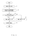
- FIG. 6 shows a flowchart of the processes performed by a coincidence degree calculation unit.
- FIG. 7 is a (second) diagram showing an exemplary configuration of a coincidence degree calculation unit.
- FIG. 8 is a (third) diagram showing an exemplary configuration of a coincidence degree calculation unit.
- FIG. 9A is a (first) diagram illustrating a pattern of two overlapping images that are offset from each other in the direction along one dimension.
- FIG. 9B is a (second) diagram illustrating a pattern of overlapping two images that are offset from each other in the direction along one dimension.
- FIG. 10A is a (first) diagram illustrating a pattern of overlapping two images that are offset from each other in the directions along two dimensions.
- FIG. 10B is a (second) diagram illustrating a pattern of overlapping two images that are offset from each other in the directions along two dimensions.
- FIG. 10C is a (third) diagram illustrating a pattern of overlapping two images that are offset from each other in the directions along two dimensions.
- FIG. 11 is a (first) diagram illustrating the overlapping of two images that include a moving object.
- FIG. 12 is a (second) diagram illustrating the overlapping of two images that include a moving object.
- FIG. 13 is a flowchart of a process of synthesizing two images.
- FIG. 14 is a diagram illustrating variation in a synthesizing ratio of two images with respect to the distance from the boundary made by the overlapping.
- FIG. 15A is a (first) diagram illustrating results of overlapping and synthesizing images P 1 and P 2 in a synthesizing area.
- FIG. 15B is a (second) diagram illustrating results of overlapping and synthesizing images P 1 and P 2 in a synthesizing area.
- FIG. 16 shows a configuration of an image synthesizing apparatus according to the second embodiment.
- FIG. 17 is a flowchart of the processes performed by an image synthesizing apparatus according to the second embodiment.
- FIG. 18 shows a configuration of an image synthesizing apparatus according to the third embodiment.
- FIG. 19 is a flowchart of the processes performed by an image synthesizing apparatus according to the third embodiment.
- FIG. 20 is a diagram illustrating pattern matching of two images that are offset in the direction along one dimension.
- FIG. 21A is a (first) diagram illustrating relationships between characteristic points when an image involves rotation.
- FIG. 21B is a (second) diagram illustrating relationships between characteristic points when an image involves rotation.
- FIG. 1 shows a principle of the present invention.
- an image synthesizing apparatus 10 includes a coincidence degree calculation unit 11 for calculating a coincidence degree, which is a degree of coincidence or similarity between plural images, a top-and-bottom determination unit 12 (an overlapping pattern determination unit) for determining a pattern of overlapping plural images, and an overlapping unit 13 for overlapping plural images on the basis of the determined pattern.
- a coincidence degree calculation unit 11 for calculating a coincidence degree, which is a degree of coincidence or similarity between plural images
- a top-and-bottom determination unit 12 an overlapping pattern determination unit
- an overlapping unit 13 for overlapping plural images on the basis of the determined pattern.
- the coincidence degree calculation unit 11 calculates a coincidence degree, which is a degree of coincidence between the input images in a prescribed area. More specifically, the coincidence degree calculation unit 11 obtains, from the images, pixels at the corresponding positions in areas near the boundary for overlapping plural images (this area is referred to as a coincidence degree calculation area hereinafter, and will be explained later in detail), and calculates a coincidence degree between plural images in a coincidence degree calculation area on the basis of those pixels.
- a coincidence degree indicates a degree of coincidence or similarity between plural images in a coincidence degree calculation area, and is calculated on the basis of the statistic relating to the pixels.
- a coincidence degree in an area between images is low, the images in that area differ greatly from each other in brightness, the colors, and the like.
- statistics relating to the pixels include the number of pixels at the corresponding positions, whether the pixel value difference between them is higher than a prescribed value, the cumulative value of the absolute values of pixel value differences, the difference between the averages of the brightness of images in a prescribed area, and the like.
- a coincidence degree calculation area is, more specifically, an area near a boundary made by overlapping plural images.
- a prescribed area is an area inward by a prescribed width from the circumference of the common area, in which plural images are overlapped, or an area on the boundary made by overlapping.
- the coincidence degree calculation area includes a moving object.
- a background area involving no movement
- pixels at the corresponding positions rarely change in brightness or color from one image to another, and accordingly, the coincidence degree in the area is high.
- the coincidence degree in an area is high
- that area can be judged to be a background.
- the coincidence degree in that area is low because pixels representing the movement of the object change greatly in brightness and color from one image to another, and thus the coincidence degree of that area is low.
- a coincidence degree in an area is low, that area can be judged to include a moving object.
- the top-and-bottom determination unit 12 determines a pattern of overlapping plural images on the basis of the coincidence degree calculated by the coincidence degree calculation unit 11 .
- the top-and-bottom determination unit 12 determines, as an overlapping pattern, a pattern that makes areas near boundaries with high coincidence degrees appear on the overlapped image (an image obtained by overlapping plural images). In other words, the top-and-bottom determination unit 12 determines, on the basis of the coincidence degree, an overlapping pattern so that one of the plural images is used mainly in the area in which plural images are overlapped.
- the overlapping unit 13 overlaps plural images on the basis of the overlapping pattern determined by the top-and-bottom determination unit 12 . As a result of this, areas near a boundary with low coincidence degrees is not synthesized on the image obtained by that overlapping.
- the image that is to be mainly used in the area where plural images are overlapped is also determined at the same time.
- the top-and-bottom determination unit 12 determines that the image is to be mainly used in the area where plural images are overlapped.
- the image synthesizing apparatus 10 calculates the coincidence degree between plural images in areas near the boundary of the common area, and overlaps and synthesizes those images so that a synthesized area near the boundary with a high coincidence degree appears on the image obtained by the overlapping. This makes it possible to prevent an object in those images from being duplexed even when the images include an object. When no object is included in those images, it is possible to prevent an unnatural rupture from being made on the boundary between those images.
- the image synthesizing apparatus 10 eliminates processes of dividing an image into plural areas to overlap images for each of such areas and processes requiring a large number of operations such as a process of dividing an image into an object part and a background part. Also, the image synthesizing apparatus 10 requires a smaller number of operations for calculating coincidence degrees, thus imposing fewer burdens on the processor than the conventional techniques.
- implementation of the image synthesizing apparatus 10 according to the present invention does not require a large-scale expansion of circuits, making the implementation of the image synthesizing apparatus 10 possible at a relatively low cost.
- the image synthesizing apparatus 10 may further include, in addition to the above configuration, a superposing unit for superposing the plural images in areas near the boundary.
- the image synthesizing apparatus 10 overlaps images by using, on the basis of coincidence degrees, a pattern that makes a boundary that is made by superposing the images unnoticeable.
- an image obtained by superposing images using this manner alone will involve jointing lines between the images, although such lines are unnoticeable.
- Use of the superposing unit for superposing plural images in areas near a boundary makes such jointing lines further unnoticeable.
- an area that is to receive a superposing process is a near-boundary area that appears on an image obtained by superposing plural images.
- the image synthesizing apparatus 10 may further include, in addition to the above configuration, an image-shooting supplement unit for generating supplement information on the basis of the offsetting amount (amount of moving vector) in a positional coordinate between an image being shot currently and an image shot previously, and for generating an outputting of the supplement information to an image shooting unit that shoots at least one of plural images.
- an image-shooting supplement unit for generating supplement information on the basis of the offsetting amount (amount of moving vector) in a positional coordinate between an image being shot currently and an image shot previously, and for generating an outputting of the supplement information to an image shooting unit that shoots at least one of plural images.
- the image synthesizing apparatus 10 may further include, in addition to the above configuration, an offsetting amount calculation unit for calculating an offsetting amount between plural images, and an image conversion unit for converting, on the basis of the offsetting amount, at least one of the plural images so that the offsetting amount is made smaller in order to overlap the plural images after the conversion.
- the image synthesizing apparatus 10 may also be included in an image shooting device.
- an image shooting device having the image synthesizing apparatus 10 may be included in a mobile phone, a PDA (Personal Digital Assistant), a personal computer, or the like.
- the embodiments discussed herein are also related to a program, a recording medium recording that program, and a program product, said program being configured to make a processor perform control equivalent to the functions implemented by the respective units that constitute the image synthesizing apparatus 10 .
- the above purposes can also be achieved by making a processor read that program and control various interfaces or the like connected to the processor in accordance with the program.
- An image synthesizing apparatus 100 according to the first embodiment overlaps and synthesizes image P 1 and image P 2 that have already been position adjusted.
- FIG. 2 shows a configuration of the image synthesizing apparatus 100 according to the first embodiment.
- the image synthesizing apparatus 100 includes a coincidence degree calculation unit 110 , a top-and-bottom determination unit 150 , and an overlapping unit 160 .
- Images P 1 and P 2 having already been position adjusted, are input to the coincidence degree calculation unit 110 .
- the coincidence degree calculation unit 110 obtains, from images P 1 and P 2 , pixels that are at corresponding positions in both images in the coincidence degree calculation areas, and calculates the coincidence degrees of the coincidence degree calculation areas.
- Coincidence degree calculation areas usually exist in plural, and accordingly the coincidence degree calculation unit 110 calculates the coincidence degree for each of the coincidence degree calculation areas.
- the top-and-bottom determination unit 150 determines how to overlap images P 1 and P 2 on the basis of the coincidence degree calculated by the coincidence degree calculation unit. More specifically, the top-and-bottom determination unit 150 determines which of the images P 1 and P 2 should appear in the overlapped images.
- the overlapping unit 160 overlaps images P 1 and P 2 in accordance with the determination made by the top-and-bottom determination unit 150 , and synthesizes the images. The image obtained by the synthesizing is output.
- the coincidence degree calculation unit 110 calculates the coincidence degree for each of a plurality of coincidence degree calculation areas (step S 2 ).
- the top-and-bottom determination unit 150 determines which of the areas have high coincidence degrees among the plurality of coincidence degree calculation areas (step S 3 ), and determines a pattern of overlapping images P 1 and P 2 on the basis of the determination result (steps S 4 and S 5 ).
- the overlapping unit 160 overlaps images P 1 and P 2 on the basis of the determination made by the top-and-bottom determination unit 150 , and synthesizes the images (step S 6 ).
- coincidence degree calculation areas for which the coincidence degree calculation unit 110 calculates the coincidence degrees.
- images P 1 and P 2 are offset in a direction along one dimension, i.e., the vertical or horizontal direction.
- the common area is a quadrangle.
- This quadrangle is made up of a side formed by a portion of the circumference of image P 1 (referred to as the image-P 1 -side boundary), a side formed by a portion of the circumference of image P 2 (referred to as the image-P 2 -side boundary), and two sides formed by portions of the circumferences of images P 1 and P 2 , respectively.
- One is an area inward by a prescribed number of pixels (or by a particular width) from the image-P 1 -side boundary.
- the other is an area inward by a prescribed number of pixels (or by a particular width) from the image-P 2 -side boundary.
- FIG. 4 shows a common area and coincidence degree calculation areas made when image P 2 is offset from image P 1 in the down right direction.
- the area in which images P 1 and P 2 are overlapped is the common area.
- the two sides of the circumference of the common area that is, two of the four sides forming the boundary, are parts of the two adjacent sides of the quadrangle forming the circumference of image P 1 .
- the other two sides of the boundary of the common area are parts of the two adjacent sides of the quadrangle forming the circumference of image P 2 .
- the former group is referred to as the image-P 1 -side boundary
- the latter group is referred to as the image-P 2 -side boundary.
- P 1 -side coincidence degree calculation area M 1 which is an area inward by a prescribed number of pixels (or by a prescribed width) from the image-P 1 -side boundary.
- P 2 -side coincidence degree calculation area M 2 which is an area inward by a prescribed number of pixels (or by a prescribed width) from the image-P 2 -side boundary.
- P 1 -side coincidence degree calculation area M 1 and P 2 -side coincidence degree calculation area M 2 are in the common area, and are L-shaped areas located around the two opposing corners among the four corners of the common area. It is not necessary to calculate the coincidence degrees of the shaded areas in the common area. This is because shaded area R 1 , located around the center of the common area, is apart from the boundary made by overlapping the images, and the coincidence degrees of shaded areas R 2 and R 3 are the same as those of P 1 -side coincidence degree calculation area M 1 and P 2 -side coincidence degree calculation area M 2 , and are useless for determining the top and the bottom of the images.
- the coincidence degree calculation unit 110 can calculate coincidence degrees using several different methods. For example, the coincidence degree calculation unit 110 may calculate a coincidence degree on the basis of the difference in pixel value between two pixels at corresponding positions, the statistic of brightness of images P 1 and P 2 , and/or the continuity between images along the boundary. It is also possible to calculate a coincidence degree for an image reduced in size to, for example, 1 ⁇ 2 vertically and horizontally by using sub-sampling.
- FIG. 5 shows an exemplary configuration of the coincidence degree calculation unit 110 that calculates a coincidence degree on the basis of a pixel value difference.
- the coincidence degree calculation unit 110 includes a boundary area selection unit 111 , difference calculation units 112 - 1 and 112 - 2 , comparison units 113 - 1 and 113 - 2 , counters 114 - 1 and 114 - 2 , and a threshold value storing unit 115 .
- the difference calculation unit 112 - 1 , the comparison unit 113 - 1 , and the counter 114 - 1 calculate the coincidence degree of P 1 -side coincidence degree calculation area M 1
- the difference calculation unit 112 - 2 , the comparison unit 113 - 2 , and the counter 114 - 2 calculate the coincidence degree of P 2 -side coincidence degree calculation area M 2
- the former group is referred to as the image-P 1 -side calculation unit
- the latter group is referred to as the image-P 2 -side calculation unit. They are basically equal to each other in configuration.
- Images P 2 and P 2 are input to the boundary area selection unit 111 .
- the boundary area selection unit 111 determines which of coincidence degree calculation areas M 1 and M 2 the input pixels are in, or whether such pixels are in an area other than coincidence degree calculation areas M 1 and M 2 .
- the boundary area selection unit 111 outputs that pixel to the P 1 -side calculation unit.
- the boundary area selection unit 111 outputs that pixel to the P 2 -side calculation unit.
- a pixel is not in either P 1 -side coincidence degree calculation area M 1 or M 2 , that pixel is not output, and the process proceeds to steps for pixels other than such pixels.
- the boundary area selection unit 111 performs this process for all input pixels.
- the difference calculation unit 112 - 1 calculates the difference between two pixels at the corresponding positions between images P 1 and P 2 , and outputs the absolute value of the calculated difference to the comparison unit 113 - 1 (the comparison unit 113 - 2 on the M 2 side).
- the comparison unit 113 - 1 compares the absolute value of the difference with a threshold value stored in the threshold value storing unit 115 .
- the counter 114 - 1 increments the counter value by one.
- the counters 114 - 1 and 114 - 2 output the coincidence degrees based on the counting results to a comparison unit 116 . In doing this, each coincidence degree is the inverse of (counter value+1).
- the comparison unit 116 as part of the top-and-bottom determination unit 150 compares the coincidence degree calculated for the P 1 side and that calculated for the P 2 side so as to determine which is the greater, and outputs the determination result to the overlapping unit 160 .
- the difference calculation unit 112 - 1 waits for pixels to be input (step S 10 ).
- the difference calculation unit 112 - 1 calculates the difference in pixel values between pixels at the corresponding positions respectively in images P 1 and P 2 (step S 11 ).
- the comparison unit 113 - 1 obtains a threshold value from the threshold value storing unit 115 (step S 12 ), and determines whether or not the difference is greater than the threshold value (step S 13 ).
- the counter 114 - 1 increments the counter value by one (step S 14 ), and the process returns to step S 10 .
- Step S 10 When pixels have not been input after a prescribe time period has elapsed (no in step S 10 ), the counter 114 - 1 terminates the counting. Thereafter, the counter 114 - 1 outputs, to the comparison unit 116 , the inverse of (counter value+1), i.e., the inverse of the value obtained by adding 1 to the counter value as the coincidence degree (step S 15 ), and terminates the process.
- Steps S 20 through S 25 which are steps for the P 2 side, are basically the same as steps S 10 through S 15 for the P 1 side, and accordingly the explanations thereof will be omitted.
- the comparison unit 116 compares the coincidence degree of the P 1 side and the coincidence degree of the P 2 side.
- the above configuration is provided with respective process blocks for the P 1 side and the P 2 side.
- a configuration is also possible in which two counters, i.e., the counters 114 - 1 and 114 - 2 , are prepared for the P 1 and P 2 sides, respectively, and the other units are shared by them.
- FIG. 7 shows an exemplary configuration of the coincidence degree calculation unit 110 that calculates a coincidence degree on the basis of the statistic of the brightness of images.
- the coincidence degree calculation unit 110 includes the boundary area selection unit 111 , Y-average calculation units 117 - 1 , 117 - 2 , 118 - 1 , and 118 - 2 , and difference calculation units 119 - 1 and 119 - 2 .
- the Y-average calculation units 117 - 1 and 118 - 1 and the difference calculation unit 119 - 1 constitute the P 1 side
- the Y-average calculation units 117 - 2 and 118 - 2 and the difference calculation unit 119 - 2 constitute the P 2 side. They are basically equal to their respective counterparts in configuration.
- the boundary area selection unit 111 When images P 1 and P 2 are input, the boundary area selection unit 111 outputs pixels in P 1 -side coincidence degree calculation area M 1 to the P 1 side on the basis of the coordinate information of the pixels, and outputs pixels in P 2 -side coincidence degree calculation area M 2 to the P 2 side.
- the respective units on the P 1 side will be explained; however, basically the same explanations can be applied to the P 2 side.
- pixels of image P 1 are input to the Y-average calculation unit 117 - 1
- pixels of image P 2 are input to the Y-average calculation unit 118 - 1
- the Y-average calculation unit 117 - 1 calculates the average value of the Y values of pixels of image P 1 so as to output the calculation result to the difference calculation unit 119 - 1
- the Y-average calculation unit 118 - 1 calculates the average value of the Y values of pixels of image P 2 so as to output the calculation result to the difference calculation unit 119 - 1 .
- the difference calculation unit 119 - 1 calculates the difference of Y-value averages between images P 1 and P 2 , and outputs the absolute value of the calculated difference to the comparison unit 116 as a coincidence degree.
- a case in which the average value of Y values is used has been explained; however, the dispersion or the deviation of Y values may be used instead of average values.
- FIG. 8 shows an exemplary configuration of the coincidence degree calculation unit 110 that calculates a coincidence degree on the basis of the continuity of a boundary.
- the coincidence degree calculation unit 110 includes the boundary area selection unit 111 , difference calculation units 120 - 1 and 120 - 2 , and cumulative addition units 121 - 1 and 121 - 2 .
- the difference calculation unit 120 - 1 and the cumulative addition unit 121 - 2 calculate a coincidence degree of the image P 1 side
- the difference calculation unit 120 - 2 and the cumulative addition unit 121 - 1 calculate a coincidence degree of the image P 2 side.
- the P 1 and P 2 sides are configured of basically the same components.
- the coincidence degree calculation unit 110 calculates the coincidence degrees of pixels on the boundary, instead of calculating those of pixels in a coincidence degree calculation area.
- the boundary area selection unit 111 outputs, to the P 1 side, pixels having been determined to be on the image-P 1 -side boundary, and outputs, to the P 2 side, pixels having been determined to be on the image-P 2 -side boundary.
- the coincidence degree of the P 1 side is calculated by cumulatively adding the absolute values of the difference between two pixels on the boundary on the P 1 side.
- the difference calculation unit 120 - 1 calculates the difference in pixel value between two pixels at the corresponding positions in images P 1 and P 2 .
- the cumulative addition unit 121 - 1 cumulatively adds the absolute values of the differences calculated by the difference calculation unit 120 - 1 , and outputs the result of the cumulative addition as the P 1 -side coincidence degree to the comparison unit 116 when it has performed the process on all pixels on the P 1 -side boundary.
- the top-and-bottom determination unit 150 determines how to overlap images P 1 and P 2 on the basis of whether the P 1 -side-near-boundary area or the P 2 -side-near-boundary area should appear on the image obtained by the overlapping. More specifically, the top-and-bottom determination unit 150 compares the coincidence degrees of the P 1 side and the P 2 side calculated by the coincidence degree calculation unit 110 .
- the top-and-bottom determination unit 150 When the top-and-bottom determination unit 150 has determined that the coincidence degree of the image-P 1 side is higher, it determines that image P 1 should be overlapped on image P 2 , and when it has determined that the coincidence degree of the image P 2 side is higher, it determines that image P 2 should be overlapped on image P 1 . It is also possible to set beforehand a default or to prompt users to determine whether the image-P 1 side or the image-P 2 side is to be the top when the coincidence degrees of the image-P 1 side and the image-P 2 side are equal.
- one of the images P 1 and P 2 is used as it is before overlapping for areas other than the common area. For example, for the area that was image P 1 before the overlapping, image P 1 is used, and for the area that was image P 2 before the overlapping, image P 2 is used.
- a different image is used depending upon whether the selected pattern makes image P 1 the top or makes image P 2 the top.
- image P 1 when image P 1 is overlapped on image P 2 , the P 1 -side boundary appears on the overlapped image (the image obtained by overlapping those images), and the P 2 -side boundary is hidden by the image P 1 .
- image P 2 is used in the common area.
- image P 2 is used in the common area.
- image P 2 is used.
- FIG. 10 show three of such patterns.
- FIGS. 10A through 10C show the patterns of overlapping images that are offset both in the right and left directions and the up and down directions for viewers.
- FIGS. 10A and 10B respectively show two overlapping patterns for a case where image P 2 is offset from image P 1 in the right down direction from the vantage of the viewer.
- image P 2 is overlapped on image P 1
- the image-P 2 -side boundary appears on the overlapped image
- the image-P 1 -side boundary is hidden in the overlapped image.
- Image P 2 is used for the common area.
- image P 1 is overlapped on image P 2 as shown in FIG. 2B
- the image-P 1 -side boundary appears on the overlapped image
- the image-P 2 -side boundary is hidden in the overlapped image.
- Image P 1 is used for the common area.
- image P 1 is used for an area that was image P 1 before the overlapping
- image P 2 is used for an area that was image P 2 before the overlapping.
- the overlapping unit 160 overlaps images P 1 and P 2 , selecting one of them as the top in accordance with that determination.
- the image synthesizing apparatus 100 overlaps plural images so that the area near the boundary having a high coincidence degree is the top. As a result of this, the area near the boundary that became the top after the overlapping appears on the overlapped image, and the area near the boundary that became the bottom after the overlapping is hidden in the overlapped image.
- the areas near the boundary are close to each other between plural images, and accordingly overlapping images so that an image having, as its circumference, a near-boundary area with a high coincidence degree at its top makes it less likely to make an unnatural rupture on the boundary on the overlapped image even when there is a moving object in areas near the boundary.
- images P 1 and P 2 include a walking person as an object. It is supposed that the person is moving from right to left from the vantage of viewers and image P 1 was shot prior to image P 2 .
- Image P 1 includes the person in the near-image-P 1 -side boundary area (this area also serves as a coincidence degree calculation area).
- Image P 2 does not include the person in either the near-image-P 1 -side boundary area or near-image-P 20 -side boundary area.
- the coincidence degree of the coincidence degree calculation area on the image-P 2 side calculated by the coincidence degree calculation unit 110 is higher than that of the image-P 1 side. Accordingly, the top-and-bottom determination unit 150 determines to overlap image P 2 onto image P 1 , and the overlapping unit 160 generates an image made of image P 1 on image P 2 .
- FIG. 12 shows an image that the overlapping unit 160 has generated by overlapping images P 1 and P 2 shown in FIG. 11 .
- the person included in the area near the image-P 1 -side boundary is hidden by image P 2 .
- an area near the image-P 2 -side boundary, not including the person is overlapped onto image P 1 , and this area does not include a moving object.
- the person included in an area other than the common area in image P 2 appears on the overlapped image.
- the image synthesizing apparatus 100 can avoid the duplexing of an object on an overlapped image.
- the overlapping unit 160 may synthesize images by superposing images P 1 and P 2 on an area near the boundary so that a rupture made near the boundary on the top image is not noticeable.
- an area in which images P 1 and P 2 are to be synthesized i.e., a synthesizing area, will be explained before explaining a process performed by the overlapping unit 160 .
- the synthesizing area made when images P 1 and P 2 that are offset in directions along two dimensions, i.e., the right and left directions and the up and down directions, are to be overlapped will be explained.
- FIG. 10A when image P 2 is on image P 1 , the area inward by a prescribed number of pixels from the boundary on the image-P 2 side of the common area (the shaded area) is the synthesizing area.
- the synthesizing area is L-shaped.
- FIG. 10A shows a case where image P 2 is offset from image P 1 to the down right direction, however, the same explanations can be applied to a case where image P 1 is offset from image P 2 to the down right direction.
- the number of pixels that should be between the synthesizing area and the boundary i.e., the width of the synthesizing area, varies depending upon the size of the entire image.
- the overlapping unit 160 determines whether or not a certain pixel is in the common area on the basis of the pixel coordinate information of the two input images.
- the overlapping unit 160 determines that the pixel is in the common area (Yes in step S 30 )
- it further determines whether or not that pixels is in the synthesizing area (step S 31 ).
- the overlapping unit 160 determines that the pixel is not in the common area (No in step S 30 ), it outputs the pixel at those coordinates together with the coordinates after the overlapping (step S 33 ). Thereby, image P 1 is used for a portion that was image P 1 before the overlapping, and image P 2 is used for a portion that was image P 2 before the overlapping.
- step S 31 when the overlapping unit 160 determines that the coordinates are in the synthesizing area (Yes in step S 31 ), it obtains the pixels corresponding to each other at those coordinates in images P 1 and P 2 , and superposes those two pixels (step S 34 ). Thereafter, the overlapping unit 160 outputs the pixel resulting from that superposition and the coordinates of the pixel after the overlapping.
- step S 31 when the overlapping unit 160 determines that the coordinates are not in the synthesizing area (No in step S 31 ) and also when image P 1 is used in the common area after overlapping on the basis of the coordinate information and the result of determination of the overlapping pattern made by the top-and-bottom determination unit 150 (Yes in step S 32 ), the overlapping unit 160 outputs the pixel from image P 1 together with the coordinates after the overlapping (step S 35 ).
- the overlapping unit 160 outputs the pixel from image P 2 together with the coordinates after the overlapping (step S 36 ).
- step S 37 When the overlapping unit 160 has performed those processes on all input pixels (step S 37 ), it terminates the process.
- FIG. 14 shows an example of variation in a synthesizing ratio between images P 1 and P 2 with respect to the distance from the boundary made by the overlapping in a case when images P 1 and P 2 are offset to the right and left directions. Note that in FIG. 14 , image P 1 is smaller than image P 2 , but this is for clearly representing that those two images are overlapped, and they do not need to be different in size.
- image P 2 is on image P 1 , and accordingly, the boundary on image P 2 appears on the overlapped image.
- 1:0 as the synthesizing ratio between image P 1 and image P 2 on the image-P 2 -side boundary
- 0:1 as the synthesizing ratio between image P 1 and image P 2 on the synthesizing-area boundary.
- FIG. 14 shows an example of changing the synthesizing ratios of images P 1 and P 2 linearly (using linear functions); however, other functions can be used.
- FIGS. 15A and 15B show results of overlapping images when image P 2 is offset from image P 1 to the down right direction.
- FIG. 15A shows a case where image P 1 is on image P 2 .
- the area near the image-P 1 -side boundary of the common area is the synthesizing area.
- the synthesizing ratio of image P 2 on the image-P 1 -side boundary is decreased to zero with decreasing distance to the synthesizing-area boundary. Consequently, as shown in FIG.
- the overlapping unit 160 overlaps and synthesizes images P 1 and P 2 , and accordingly ruptures appearing near the boundary between the images can be made unnoticeable.
- image P 2 is on image P 1 .
- the area near the image-P 2 -side boundary in the common area is the synthesizing area, and the synthesizing ratio of image P 1 on the image-P 2 -side boundary decreases to zero with decreasing distance to the boundary of the synthesizing area.
- the area near the boundary between image P 1 , which is in white, and image P 2 which is in dark gray, gradually changes in color from white to light gray and finally to dark gray, making the boundary unnoticeable.
- the overlapping unit 160 superposes and synthesizes images P 1 and P 2 in the area near the boundary so that unnatural ruptures are not made near the boundary.
- the image synthesizing apparatus 100 determines, on the basis of the coincidence degrees before superposing images P 1 and P 2 , which of such images is to be the top when they are overlapped so that the problem of duplexing can be made to be unlikely to occur in the common area.
- the overlapping unit 160 overlaps the two images on the basis of that determination, and thereafter superposes those images near the boundary made by the overlapping. Accordingly, the image synthesizing apparatus 100 makes it possible to avoid the problem of duplexing even when images near the boundary are overlapped.
- the image synthesizing apparatus 200 according to the present embodiment overlaps and synthesizes plural still images shot at positions offset by a prescribed width.
- a pole In order to offset the positions by a prescribed width, it is possible to provide a pole to an image shooting apparatus so that the image shooting apparatus is turned at a prescribed angle on that pole, or to shoot images with the shooting person turning his/her body.
- the image synthesizing apparatus 200 outputs, to an image shooting apparatus connected to the image synthesizing apparatus 200 , supplement information used for shooting an image by applying a prescribed-width offset to the image shot previously.
- the image synthesizing apparatus 200 and the image shooting apparatus may have a communication function to communicate with each other so that the image synthesizing apparatus 200 can transmit supplement information to the image shooting apparatus.
- Examples of the image shooting apparatus include a still camera and a video camera.
- the image shooting apparatus may be included in a mobile phone, a PDA (Personal Digital Assistant), a personal computer, or the like.
- FIG. 16 shows a configuration of the image synthesizing apparatus 200 having a function of outputting or transmitting supplement information to an image shooting apparatus.
- the image synthesizing apparatus 200 includes an offsetting amount storing unit 210 , image-shooting supplement information 220 , a coincidence-degree calculation unit 110 , a top-and-bottom determination unit 150 , and an overlapping unit 160 .
- the offsetting amount storing unit 210 stores a width that is prescribed as an offsetting amount. This offsetting amount may be set by users, or can be set as a default setting of the device.
- the image-shooting supplement information 220 generates, on the basis of a previously shot image (first image) and the offsetting amount, supplement information used for displaying, on the viewfinder of an image shooting apparatus, the edges of the first image and a prescribed width as an offsetting amount, and thereafter, the image-shooting supplement information 220 outputs or transmits the supplement information to the image shooting apparatus.
- the image shooting apparatus superposes the edges of the first image and the line or frame indicating the offsetting amount on the viewfinder on which the shooting object has been output.
- the shooting person when shooting the second and subsequent images, can shoot the next image, which is offset by a prescribed width from the first image.
- the shot second image is input to the image synthesizing apparatus 200 .
- the coincidence degree calculation unit 110 , the top-and-bottom determination unit 150 , and the overlapping unit 160 overlap the first and the second images. This overlapping process is as has already been explained.
- the second embodiment executes steps S 40 and S 41 instead of step S 1 in the first embodiment.
- the user uses the image shooting apparatus to shoot a first image.
- the image shooting apparatus transmits or outputs that first image to the image synthesizing apparatus 200 (step S 40 ).
- the image synthesizing apparatus 200 calculates the coordinates of a frame indicating the edges of the first image and of a line indicating the position apart by a prescribed width from that frame, and outputs or transmits to the image shooting apparatus the calculation result as supplement information.
- the image shooting apparatus superposes the frame indicating the edges of the first image and the line indicating the offsetting amount on the viewfinder on which the shooting object has been output.
- the user shoots an images that is offset by a prescribed width from the first image, on the basis of the frame or line superposed on the viewfinder, and the second image that has been shot is output or transmitted to the image synthesizing apparatus 200 (step S 41 ).
- step S 2 processes are performed for overlapping the first and second images as images P 1 and P 2 , respectively.
- the processes in and after step S 2 are similar to those in the first embodiment, and explanations thereof will be omitted.
- the image synthesizing apparatus 200 has the merit that it can prepare supplement information that can be used for shooting second images, in addition to the merit provided by the image synthesizing apparatus 100 according to the first embodiment. Thereby, it is possible to shoot plural images that are offset by a prescribed width.
- an offsetting amount is not prescribed, and an image synthesizing apparatus 300 calculates an offsetting amount between images P 1 and P 2 , and overlaps images P 1 and P 2 after correcting the offset.
- the image synthesizing apparatus 300 includes an offsetting amount calculation unit 310 , an image conversion unit 320 , the coincidence degree calculation unit 110 , the top-and-bottom determination unit 150 , and the overlapping unit 160 .
- the offsetting amount calculation unit 310 calculates the offsetting amount between input images P 1 and P 2 .
- the image conversion unit 320 converts, on the basis of the offsetting amount, one of those two images so that the same object in them is positioned at the same coordinates.
- the coincidence degree calculation unit 110 , the top-and-bottom determination unit 150 , and the overlapping unit 160 have already been explained.
- the third embodiment executes steps S 50 through S 52 between steps S 1 and S 2 , in contrast to the first embodiment shown in FIG. 3 .
- step S 1 When two images P 1 and P 2 are input to the image synthesizing apparatus 300 (step S 1 ), the offsetting amount calculation unit 310 calculates the offsetting amount between the two images (step S 50 ). Next, the image conversion unit 320 converts one of images P 1 and P 2 on the basis of the calculated offsetting amount so that the offset is cancelled (step S 51 ). Thereafter, the coincidence degree calculation unit 110 determines the common area on the basis of images P 1 and P 2 after the conversion (step S 52 ), and executes steps S 2 and subsequent steps. The processes in and after step S 2 are as have already been explained.
- the offsetting amount calculation unit 310 obtains edge images E 1 and E 2 by applying a Sobel filter to input images P 1 and P 2 .
- a Sobel filter is for detecting outlines by carrying out a spatial first order derivative.
- the offsetting amount calculation unit 310 extracts a characteristic point from one of edge images E 1 and E 2 (edge image E 1 in this example), and extracts, from the other edge image (edge image E 2 in this example), a portion near the coordinates of that characteristic point.
- the offsetting amount calculation unit 310 overlaps the images near the characteristic points of edge images E 1 and E 2 (pattern matching) so as to calculate the offsetting amount.
- small-area-image data (referred to as a window hereinafter) in a background image is set, and the target image is scanned so as to detect areas that are equal in size to each other and that have the pixel values corresponding to those in this window.
- the difference between the coordinates in the window of the background window and those in the window of the target image is calculated, and the resultant values are handled as ⁇ x and ⁇ y.
- the image shooting apparatus when the shooting person has shot images holding, with his/her hands, the image shooting apparatus instead of using a tripod stand, the second shot images often involve not only parallel movements but also rotation. In such a case, it is necessary to calculate the offsetting amounts ⁇ x and ⁇ Y separately for all characteristic points because the values of all offsetting amounts ⁇ x and ⁇ y differ depending upon the coordinates of characteristic points.
- An example of a method of obtaining the offsetting amounts for an entire image is Homography. Homography is a technique used for linking plural images (mosaicing), and is an algorithm for calculating offsetting amounts of an entire image from plural small areas (characteristic points) that are to be focused on in the image.
- FIG. 21A shows an example where four characteristic points T 1 through T 4 are extracted from image PT 1 and those respective points have the coordinates shown below.
- T1 (x1, y1)
- T2 (x2, y2)
- T3 (x3, y3)
- T4 (x4, y4)
- FIG. 21B shows an example where characteristic points T 1 ′ through T 4 ′ are extracted from image PT 2 , and those respective points have the coordinates below.
- T1′ (x1′,y1′)
- T2′ (x2′,y2′)
- T3′ (x3′,y3′)
- T4′ (x4′,y4′)
- M represents a matrix, and is called a Homography Matrix. It is possible to calculate a Homography Matrix from a group of coordinates of characteristic points existing both in image PT 1 and image PT 2 .
- k represents an arbitrary number except for zero, and m 1 through m 9 are arbitrary numbers.
- m 1 through m 9 are arbitrary numbers.
- Using the coordinates of several groups of characteristic points makes it possible to calculate the parameters of K and m 1 through m 9 .
- Performing Homography Matrix and matrix calculations of an arbitrary coordinate point (x,y) in image PT 1 makes it possible to calculate a point (x′, y′) in image PT 2 corresponding to image PT 1 (x, y).
- the offsetting amount calculation unit 310 calculates the offsetting amounts between two images as described above, and converts, on the basis of the calculated offsetting amount, one of images P 1 and P 2 so that the offset is cancelled. Thereafter, the coincidence degree calculation unit 110 , the top-and-bottom determination unit 150 , and the overlapping unit 160 determine, on the basis of the coincidence degree, a pattern for overlapping images P 1 and P 2 , and overlaps them. Accordingly, the image synthesizing apparatus 300 makes it possible to overlap and synthesize images with the offset between them being cancelled beforehand even when such images are not position adjusted beforehand.
- the image synthesizing apparatuses 100 , 200 , and 300 according to the present invention can be implemented in various forms. Hereinafter, implementations of the image synthesizing apparatuses 100 , 200 , and 300 according to the present invention will be explained.
- the image synthesizing apparatuses 100 , 200 , and 300 can be implemented using, for example, a computer.
- a computer (not shown) is equipped with, for example, a CPU (Central Processing Unit), a memory device, and an input/output interface, all of which are connected to one another through a bus.
- Examples of an input/output interface include a liquid crystal panel, a touch panel, various types of buttons and dials, and the like.
- a program is stored in the memory device for making the processor execute processes assigned to the respective units that constitute the image synthesizing apparatuses 100 , 200 , and 300 .
- the CPU uses the memory device to execute the program, the image synthesizing apparatuses 100 , 200 , and 300 are implemented.
- those image synthesizing apparatuses can be provided to various types of apparatuses.
- an image shooting apparatus or the like such as a still camera or a video camera is explained.
- Such an image shooting apparatus includes, in most cases, a lens, an image pick-up element, a controller (a non-general-purpose processor), a display device, a memory device, an input/output interface, and an auxiliary storage device.
- a lens forms an image of the object on the image pick-up element.
- An image pick-up element converts the formed image into electric signals so as to output the signals to the controller.
- a controller controls the memory device, the storage device, the interface, and the display device.
- the controller also stores, in the memory device, a program for executing processes assigned to the respective units that constitute the image synthesizing apparatus.
- the controller reads that program from the memory device so as to execute it. Thereby, the image shooting apparatuses to be provided to the image synthesizing apparatus are implemented.
- a computer chip for controlling various types of interfaces to perform processes assigned to the respective units that constitute the image synthesizing apparatus so that the image shooting apparatus to be provided to the image synthesizing apparatus is implemented by the computer chip controlling the various devices that constitute the image shooting apparatus.
- the image shooting apparatus including the image synthesizing apparatus by incorporating, into the image shooting apparatus (firmware), a memory device or the like that has recorded a program for making a processor execute processes assigned to the respective units constituting the image synthesizing apparatus.
- examples of an apparatus including an image shooting apparatus having the image synthesizing apparatus 100 , 200 , or 300 include a PDA (Personal Digital Assistant), a personal computer, and the like.
- PDA Personal Digital Assistant
- a computer-readable storage medium stores the program beforehand, the program is read from that medium to an apparatus that is to implement the image synthesizing apparatus, the program is stored in the memory device or an external storage device, and the program is read to the CPU of the computer so as to be executed.
- the program server converts the program data expressing the program into program data signals, the program data signals are modulated by a modem into transmission signals, and the transmission signals are output to the communication line.
- the apparatus that receives the program uses a modem to demodulate the received transmission signals so as to obtain the program data signals, and converts the obtained program data signals in order to obtain the program data.
- program data signals can also be transmitted.
- a computer in a telephone station or the like may exist between a computer transmitting the program and a computer downloading that program.
- a coincidence degree which indicates the degree of coincidence between plural images in an area near the boundary of the common area
- a pattern for overlapping the plural images is determined on the basis of the coincidence degree, and the plural images are overlapped and synthesized on the basis of that pattern.
Landscapes
- Engineering & Computer Science (AREA)
- Multimedia (AREA)
- Signal Processing (AREA)
- Physics & Mathematics (AREA)
- General Physics & Mathematics (AREA)
- Theoretical Computer Science (AREA)
- Image Processing (AREA)
- Studio Devices (AREA)
- Studio Circuits (AREA)
- Apparatus For Radiation Diagnosis (AREA)
Abstract
Description
- Japanese Laid-open Patent Publication No. 2000-316125
Patent Document 2 - Japanese Laid-open Patent Publication No. 2004-72685
x′=x+Δx
y′=y+Δy
T1=(x1, y1)
T2=(x2, y2)
T3=(x3, y3)
T4=(x4, y4)
T1′=(x1′,y1′)
T2′=(x2′,y2′)
T3′=(x3′,y3′)
T4′=(x4′,y4′)
Tn=MTn′
Claims (16)
Applications Claiming Priority (1)
| Application Number | Priority Date | Filing Date | Title |
|---|---|---|---|
| PCT/JP2007/001038 WO2009040872A1 (en) | 2007-09-25 | 2007-09-25 | Image synthesis device and method |
Related Parent Applications (1)
| Application Number | Title | Priority Date | Filing Date |
|---|---|---|---|
| PCT/JP2007/001038 Continuation WO2009040872A1 (en) | 2007-09-25 | 2007-09-25 | Image synthesis device and method |
Publications (2)
| Publication Number | Publication Date |
|---|---|
| US20100172585A1 US20100172585A1 (en) | 2010-07-08 |
| US8774495B2 true US8774495B2 (en) | 2014-07-08 |
Family
ID=40510787
Family Applications (1)
| Application Number | Title | Priority Date | Filing Date |
|---|---|---|---|
| US12/724,871 Expired - Fee Related US8774495B2 (en) | 2007-09-25 | 2010-03-16 | Image synthesizing apparatus and method of synthesizing images |
Country Status (3)
| Country | Link |
|---|---|
| US (1) | US8774495B2 (en) |
| JP (1) | JP4830023B2 (en) |
| WO (1) | WO2009040872A1 (en) |
Cited By (4)
| Publication number | Priority date | Publication date | Assignee | Title |
|---|---|---|---|---|
| US10217257B1 (en) * | 2015-03-17 | 2019-02-26 | Amazon Technologies, Inc. | Process for contextualizing continuous images |
| US11223810B2 (en) * | 2019-10-28 | 2022-01-11 | Black Sesame Technologies Inc. | Color balance method and device, on-board equipment and storage medium |
| US11450083B2 (en) * | 2019-09-27 | 2022-09-20 | Honeywell International Inc. | Dual-pattern optical 3D dimensioning |
| US11639846B2 (en) | 2019-09-27 | 2023-05-02 | Honeywell International Inc. | Dual-pattern optical 3D dimensioning |
Families Citing this family (13)
| Publication number | Priority date | Publication date | Assignee | Title |
|---|---|---|---|---|
| JP5604738B2 (en) * | 2009-04-08 | 2014-10-15 | 独立行政法人海上技術安全研究所 | Progress crack detection method, apparatus and program |
| KR20110131949A (en) * | 2010-06-01 | 2011-12-07 | 삼성전자주식회사 | Image processing apparatus and method |
| US8675085B2 (en) * | 2010-07-14 | 2014-03-18 | James Randall Beckers | Camera that combines images of different scene depths |
| JP5888899B2 (en) * | 2011-08-10 | 2016-03-22 | キヤノン株式会社 | Video processing apparatus, video processing method, and program |
| JP5729237B2 (en) | 2011-09-26 | 2015-06-03 | カシオ計算機株式会社 | Image processing apparatus, image processing method, and program |
| JP2013153429A (en) * | 2011-12-27 | 2013-08-08 | Canon Inc | Image processing apparatus, image display system, image processing method and image processing program |
| JP5966584B2 (en) * | 2012-05-11 | 2016-08-10 | ソニー株式会社 | Display control apparatus, display control method, and program |
| JP6467787B2 (en) * | 2014-05-27 | 2019-02-13 | 株式会社リコー | Image processing system, imaging apparatus, image processing method, and program |
| KR102551099B1 (en) | 2017-01-13 | 2023-07-05 | 엘지이노텍 주식회사 | Apparatus of providing an around view, method thereof and vehicle having the same |
| CN112700486B (en) * | 2019-10-23 | 2024-05-07 | 浙江菜鸟供应链管理有限公司 | Method and device for estimating depth of road surface lane line in image |
| CN113163137A (en) * | 2021-04-29 | 2021-07-23 | 众立智能科技(深圳)有限公司 | Method and system for realizing multi-picture superposition of Haisi coding and decoding chip |
| JP7796582B2 (en) * | 2022-04-20 | 2026-01-09 | 株式会社Screenホールディングス | Image acquisition device and image acquisition method |
| US20240412710A1 (en) * | 2023-06-06 | 2024-12-12 | Mobeus Industries, Inc. | Overlaying displayed digital content with regional transparency and regional lossless compression transmitted over a communication network via processing circuitry |
Citations (9)
| Publication number | Priority date | Publication date | Assignee | Title |
|---|---|---|---|---|
| JPH0993431A (en) | 1995-09-26 | 1997-04-04 | Canon Inc | Panorama image synthesizer |
| JPH10105677A (en) | 1996-09-26 | 1998-04-24 | Sharp Corp | Method and device for joining pictures |
| JP2000316125A (en) | 1999-04-28 | 2000-11-14 | Sharp Corp | Image synthesis device |
| US6549681B1 (en) * | 1995-09-26 | 2003-04-15 | Canon Kabushiki Kaisha | Image synthesization method |
| US20030206653A1 (en) * | 1995-07-28 | 2003-11-06 | Tatsushi Katayama | Image sensing and image processing apparatuses |
| JP2004072685A (en) | 2002-08-09 | 2004-03-04 | Sharp Corp | Image combining device, image combining method, image combining program, and recording medium storing image combining program |
| US20040075749A1 (en) * | 2001-06-27 | 2004-04-22 | Tetsujiro Kondo | Communication apparatus and method |
| US20060078224A1 (en) * | 2002-08-09 | 2006-04-13 | Masashi Hirosawa | Image combination device, image combination method, image combination program, and recording medium containing the image combination program |
| US20070098300A1 (en) * | 1992-04-09 | 2007-05-03 | Olympus Optical Co., Ltd. | Image processing apparatus |
-
2007
- 2007-09-25 JP JP2009534065A patent/JP4830023B2/en not_active Expired - Fee Related
- 2007-09-25 WO PCT/JP2007/001038 patent/WO2009040872A1/en not_active Ceased
-
2010
- 2010-03-16 US US12/724,871 patent/US8774495B2/en not_active Expired - Fee Related
Patent Citations (10)
| Publication number | Priority date | Publication date | Assignee | Title |
|---|---|---|---|---|
| US20070098300A1 (en) * | 1992-04-09 | 2007-05-03 | Olympus Optical Co., Ltd. | Image processing apparatus |
| US20030206653A1 (en) * | 1995-07-28 | 2003-11-06 | Tatsushi Katayama | Image sensing and image processing apparatuses |
| JPH0993431A (en) | 1995-09-26 | 1997-04-04 | Canon Inc | Panorama image synthesizer |
| US6549681B1 (en) * | 1995-09-26 | 2003-04-15 | Canon Kabushiki Kaisha | Image synthesization method |
| JPH10105677A (en) | 1996-09-26 | 1998-04-24 | Sharp Corp | Method and device for joining pictures |
| JP2000316125A (en) | 1999-04-28 | 2000-11-14 | Sharp Corp | Image synthesis device |
| US20040075749A1 (en) * | 2001-06-27 | 2004-04-22 | Tetsujiro Kondo | Communication apparatus and method |
| JP2004072685A (en) | 2002-08-09 | 2004-03-04 | Sharp Corp | Image combining device, image combining method, image combining program, and recording medium storing image combining program |
| US20060078224A1 (en) * | 2002-08-09 | 2006-04-13 | Masashi Hirosawa | Image combination device, image combination method, image combination program, and recording medium containing the image combination program |
| US7623733B2 (en) | 2002-08-09 | 2009-11-24 | Sharp Kabushiki Kaisha | Image combination device, image combination method, image combination program, and recording medium for combining images having at least partially same background |
Non-Patent Citations (1)
| Title |
|---|
| International Search Report mailed Nov. 13, 2007 in corresponding PCT/JP2007/001038. |
Cited By (5)
| Publication number | Priority date | Publication date | Assignee | Title |
|---|---|---|---|---|
| US10217257B1 (en) * | 2015-03-17 | 2019-02-26 | Amazon Technologies, Inc. | Process for contextualizing continuous images |
| US11450083B2 (en) * | 2019-09-27 | 2022-09-20 | Honeywell International Inc. | Dual-pattern optical 3D dimensioning |
| US11639846B2 (en) | 2019-09-27 | 2023-05-02 | Honeywell International Inc. | Dual-pattern optical 3D dimensioning |
| US12135203B2 (en) | 2019-09-27 | 2024-11-05 | Honeywell International Inc. | Dual-pattern optical 3D dimensioning |
| US11223810B2 (en) * | 2019-10-28 | 2022-01-11 | Black Sesame Technologies Inc. | Color balance method and device, on-board equipment and storage medium |
Also Published As
| Publication number | Publication date |
|---|---|
| WO2009040872A1 (en) | 2009-04-02 |
| JP4830023B2 (en) | 2011-12-07 |
| US20100172585A1 (en) | 2010-07-08 |
| JPWO2009040872A1 (en) | 2011-01-13 |
Similar Documents
| Publication | Publication Date | Title |
|---|---|---|
| US8774495B2 (en) | Image synthesizing apparatus and method of synthesizing images | |
| US11743416B2 (en) | Apparatus and methods for the storage of overlapping regions of imaging data for the generation of optimized stitched images | |
| CN110622497B (en) | Device with cameras having different focal lengths and method of implementing a camera | |
| CN111557016B (en) | Method and apparatus for generating images including simulated motion blur | |
| JP4783461B2 (en) | Image composition apparatus and method | |
| US10452945B2 (en) | Image generating device, electronic device, image generating method and recording medium | |
| JP3714163B2 (en) | Video display system | |
| US9619861B2 (en) | Apparatus and method for improving quality of enlarged image | |
| US10489885B2 (en) | System and method for stitching images | |
| CN109218606B (en) | Image pickup control apparatus, control method thereof, and computer readable medium | |
| US9225901B2 (en) | Image capturing apparatus, control method thereof, and storage medium | |
| US12262156B2 (en) | White balance processing method and electronic device | |
| US9479689B2 (en) | Imaging device and focusing-verification display method | |
| US11373282B2 (en) | Image processing apparatus and method | |
| JP2019161397A (en) | Control device, program, and control method | |
| US10606149B2 (en) | Information processing device, information processing method, and program | |
| WO2017179111A1 (en) | Display system and information processing method | |
| CN115174878A (en) | Projection picture correction method, apparatus and storage medium | |
| US20220165021A1 (en) | Apparatus, system, method, and non-transitory medium | |
| CN117135420A (en) | Image synchronization method and related equipment | |
| KR101632514B1 (en) | Method and apparatus for upsampling depth image | |
| JP3757979B2 (en) | Video display system | |
| KR20240054134A (en) | Learning-based image quality improvement method using image of image sensor and electronic deviec supporting the same | |
| TWI807495B (en) | Method of virtual camera movement, imaging device and electronic system | |
| Marinić et al. | Creating a Surround View Algorithm with Implementation on a Real Embedded ADAS Platform |
Legal Events
| Date | Code | Title | Description |
|---|---|---|---|
| AS | Assignment |
Owner name: FUJITSU LIMITED, JAPAN Free format text: ASSIGNMENT OF ASSIGNORS INTEREST;ASSIGNORS:MURASHITA, KIMITAKA;SHIMIZU, MASAYOSHI;CHUJO, KAORU;AND OTHERS;SIGNING DATES FROM 20100215 TO 20100223;REEL/FRAME:024087/0758 |
|
| CC | Certificate of correction | ||
| FEPP | Fee payment procedure |
Free format text: MAINTENANCE FEE REMINDER MAILED (ORIGINAL EVENT CODE: REM.) |
|
| LAPS | Lapse for failure to pay maintenance fees |
Free format text: PATENT EXPIRED FOR FAILURE TO PAY MAINTENANCE FEES (ORIGINAL EVENT CODE: EXP.) |
|
| STCH | Information on status: patent discontinuation |
Free format text: PATENT EXPIRED DUE TO NONPAYMENT OF MAINTENANCE FEES UNDER 37 CFR 1.362 |
|
| FP | Lapsed due to failure to pay maintenance fee |
Effective date: 20180708 |