US8773354B2 - Method utilized in three-dimensional pointing system - Google Patents
Method utilized in three-dimensional pointing system Download PDFInfo
- Publication number
- US8773354B2 US8773354B2 US13/279,332 US201113279332A US8773354B2 US 8773354 B2 US8773354 B2 US 8773354B2 US 201113279332 A US201113279332 A US 201113279332A US 8773354 B2 US8773354 B2 US 8773354B2
- Authority
- US
- United States
- Prior art keywords
- sensed
- sensing area
- determining
- dimensional information
- information
- Prior art date
- Legal status (The legal status is an assumption and is not a legal conclusion. Google has not performed a legal analysis and makes no representation as to the accuracy of the status listed.)
- Active, expires
Links
Images


Classifications
-
- G—PHYSICS
- G06—COMPUTING OR CALCULATING; COUNTING
- G06F—ELECTRIC DIGITAL DATA PROCESSING
- G06F3/00—Input arrangements for transferring data to be processed into a form capable of being handled by the computer; Output arrangements for transferring data from processing unit to output unit, e.g. interface arrangements
- G06F3/01—Input arrangements or combined input and output arrangements for interaction between user and computer
- G06F3/03—Arrangements for converting the position or the displacement of a member into a coded form
- G06F3/033—Pointing devices displaced or positioned by the user, e.g. mice, trackballs, pens or joysticks; Accessories therefor
- G06F3/0354—Pointing devices displaced or positioned by the user, e.g. mice, trackballs, pens or joysticks; Accessories therefor with detection of 2D relative movements between the device, or an operating part thereof, and a plane or surface, e.g. 2D mice, trackballs, pens or pucks
- G06F3/03542—Light pens for emitting or receiving light
-
- G—PHYSICS
- G06—COMPUTING OR CALCULATING; COUNTING
- G06F—ELECTRIC DIGITAL DATA PROCESSING
- G06F3/00—Input arrangements for transferring data to be processed into a form capable of being handled by the computer; Output arrangements for transferring data from processing unit to output unit, e.g. interface arrangements
- G06F3/01—Input arrangements or combined input and output arrangements for interaction between user and computer
- G06F3/03—Arrangements for converting the position or the displacement of a member into a coded form
- G06F3/0304—Detection arrangements using opto-electronic means
-
- G—PHYSICS
- G06—COMPUTING OR CALCULATING; COUNTING
- G06F—ELECTRIC DIGITAL DATA PROCESSING
- G06F3/00—Input arrangements for transferring data to be processed into a form capable of being handled by the computer; Output arrangements for transferring data from processing unit to output unit, e.g. interface arrangements
- G06F3/01—Input arrangements or combined input and output arrangements for interaction between user and computer
- G06F3/03—Arrangements for converting the position or the displacement of a member into a coded form
- G06F3/041—Digitisers, e.g. for touch screens or touch pads, characterised by the transducing means
- G06F3/042—Digitisers, e.g. for touch screens or touch pads, characterised by the transducing means by opto-electronic means
Definitions
- the present invention relates to a three-dimensional (3D) pointing system, and more particularly, to a method utilized in a 3D pointing system for determining a position of a pointing device in the 3D pointing system.
- Pointing system generally provides a user input and information related to space status to a computer or an electronic device.
- the types of pointing systems include a mouse, a trace ball, a touch panel, etc.
- the present related technology has developed a 3D pointing structure which detects the user's body motion by utilizing a camera or a tracking sensor, and utilizes the detected motion as the user input.
- the conventional structures often have some accompanying limitations. For example, the user has to stay in the sensing area of the camera or the tracking sensor such that the body motion is capable of being detected accurately.
- the size of the pointing device is comparatively large and is generally disposed at a position near the display device, which increases the size of the display device inevitably.
- the conventional 3D pointing structures are lack of accuracy and efficiency on estimating the space information input by the user. Therefore, the conventional technologies still have room for improvement.
- the present invention provides a method utilized in a 3D pointing system for determining a position and related space status information of a pointing device within the 3D pointing system.
- an exemplary method utilized in a 3D pointing system includes a pointing device, a display panel and a sensor array.
- the sensor array is embedded within the display panel.
- the exemplary method determines at least one space status information corresponding to the pointing device.
- the exemplary method includes: utilizing the pointing device to project a pointer onto the display panel to form a projection image; utilizing the sensor array to generate a sensed image that includes the projection image, wherein the sensed image includes a plurality of pixels; calculating a plurality of sum of pixels value of various sensing areas and the maximum value of the sum is obtained.
- the first sensed value is decided by the maximum value of the sum. Determining a first dimensional information and a second dimensional information of the at least one space status information according to the plurality of first sensed values.
- the first dimensional information and the second dimensional information are at the center of the first sensed value.
- the exemplary method further includes: establishing a second sensing area within the sensed image according to the first dimensional information and the second dimensional information; adjusting the size of the second sensing area, determining a third dimensional information of the at least one space status information according to a variation of a second sensed value within the second sensing area.
- the exemplary method further includes: determining a plurality of third sensing areas with a rotation relationship within the sensed image according to the first dimensional information and the second dimensional information; generating a plurality of sensed values respectively corresponding to the plurality of third sensing areas; determining a rotation information of the at least one space status information according to the plurality of third sensed values.
- the exemplary method further includes: determining a tilt information of the at least one space status information according to a geometry ratio corresponding to the projection image within the sensed image.
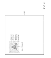
- FIG. 1 is a structure diagram illustrating a 3D pointing system employing the method of the present invention.
- FIG. 2 is a concept diagram illustrating how to determine first dimensional information and second dimensional information according to the method of the present invention.
- FIG. 3 is another concept diagram illustrating how to determine the first dimensional information and the second dimensional information according to the method of the present invention.
- FIG. 4 is a concept diagram illustrating how to determine third dimensional information according to the method of the present invention.
- FIG. 5 is a concept diagram illustrating how to determine rotation information according to the method of the present invention.
- FIG. 6 is another concept diagram illustrating how to determine the rotation information with the method of the present invention.
- FIG. 7 is a concept diagram illustrating how to determine tilt information according to the method of the present invention.
- FIG. 8 is a diagram illustrating space and status relationships determined by the method of the present invention.
- FIG. 9 is a flowchart illustrating an exemplary embodiment of the method of the present invention.
- FIG. 10 illustrates a first pattern of the pointer within the 3D pointing system which employs the method of the present invention.
- FIG. 11 illustrates a second pattern of the pointer within the 3D pointing system which employs the method of the present invention.
- FIG. 12 illustrates a third pattern of the pointer within the 3D pointing system which employs the method of the present invention.
- FIG. 13 illustrates a fourth pattern of the pointer within the 3D pointing system which employs the method of the present invention.
- FIG. 14 illustrates a fifth pattern of the pointer within the 3D pointing system which employs the method of the present invention.
- FIG. 1 is a structure diagram illustrating a 3D pointing system employing the method of the present invention.
- the 3D pointing system 100 includes a pointing device 110 and a sensor array 120 .
- the sensor array 120 is embedded within a display panel 125 , and therefore forms a sensing system.
- the sensor array 120 substantially forms a plane parallel with a display plane of the display panel 125 .
- the pointing device 110 generates a projection beam for projecting a pointer 115 with a specific pattern onto the display panel 125 to form a projection image P.
- a user may hold the pointing device 110 and input specific control information via shaking or rotating the pointing device 110 .
- the method of the present invention determines position and status (e.g., tilt or rotation) of the pointing device 110 in the space by the projection image P. Next, analyzing the related information may understand the control information the user inputs.
- the method of the present may be performed by a processing device (not shown) in a software or hardware manner.
- the processing device determines space status information corresponding to the pointing device 110 according to the sensed information (e.g., an output sensed image) generated by the sensor array 120 , wherein the space status information may include first dimensional information X, second dimensional information Y, third dimensional information Z, rotation information ⁇ , and tilt information ⁇ .
- the space status information may include first dimensional information X, second dimensional information Y, third dimensional information Z, rotation information ⁇ , and tilt information ⁇ .
- the first dimensional information X, the second dimensional information Y, and the third dimensional information Z represent a corresponding position of the pointing device 110 within the Cartesian coordinate system.
- the rotation information ⁇ represents an included angle between a projection of the pointing device 110 mapped onto the XY plane and the X axis.
- the tilt information ⁇ represents an included angle between the pointing device 110 and the Z axis.
- a sensed image SeF that includes the projection image P is generated via the sensor array 120 , and the sensed image Sef includes a plurality of pixels, wherein each pixel corresponds to a plurality of brightness values instantly generated by the sensor array 120 (i.e., respectively generated by sensing units of the pixel).
- FIG. 2 illustrates how to determine the first dimensional information X and the second dimensional information Y included in the space status information of the pointing device 110 .
- the first dimensional information X and the second dimensional information Y represent a projection position of the central point of the pointer 115 within the pointing device 110 mapped onto the sensor array 120 .
- the method of the present invention calculates a plurality of sum of sensed values respectively corresponding to a plurality of first sensing areas 200 _ 1 - 200 _n within the sensed image Sef, wherein each of the first sensing areas 200 _ 1 - 200 _n further includes a plurality of pixels Pi ( FIG. 2 only shows the pixels in the first sensing area 200 _3m+).
- the first sensed value is derived from calculating a sum of the brightness values of the pixels within the first sensing area. After the first sensed value in each first sensing area is calculated, the first dimensional information X and the second dimensional information Y of the space status information are determined.
- the method of the present invention determines a maximum value among the first sensed values. For example, since the position of the projection image P is substantially at the first sensing areas 200 _ 1 , 200 _ 2 , 200 _m+1 and 200 _m+2, the first sensing areas theoretically include larger first sensed values. Moreover, the portion of the first sensing area 200 _m+1 which includes part of the projection image P is close to the central point O, the portion would have a larger brightness value. Therefore, the first sensed value of the first sensing area 200 _m+1 would be larger than the first sensed values of the first sensing areas 200 _ 1 , 200 _ 2 and 200 _m+2.
- the first dimensional information X and the second dimensional information Y may be determined. Please refer to FIG. 3 for details directed to determining the first dimensional information X and the second dimensional information Y.
- the brightness value of each pixel of the selected first sensing area 200 _m+1 is observed. Since the central point O of the projection image P (which corresponds to the central point of the pointer 115 of the pointing device 110 and therefore has the largest projection beam intensity) lies at the position of the pixel (8, m+2). Therefore, this pixel (8, m+2) has the largest brightness value.
- the method of the present invention utilizes a related position (8, m+2) of the pixel that has the largest brightness value within the selected first sensing area to determine that the first dimensional information X and the second dimensional information Y of the pointing device 110 at this moment is (8, m+2).
- the third dimensional information Z of the space status information may be determined according to the first dimensional information X and the second dimensional information Y.
- FIG. 4 for details directed to determining the third dimensional information Z.
- the third dimensional information Z represents the distance between the pointing device 110 and the sensor array 120 . Therefore, the value corresponding to the third dimensional information Z may be derived according to the size of the projection image P.
- the present invention determines the size of the projection image P according to a second sensing area whose size is increased progressively, such that the third dimensional information Z is determined.
- the method of the present invention establishes an initial size 301 of a second sensing area within the sensed image SeF where the second sensing area may correspond to the minimum value a of the third dimensional information Z, and the central point of the initial size 301 of the second sensing area is the central point position P (8, m+2) of the projection image P.
- a second sensed value S 1 within the initial size 301 of the second sensing area (it may be derived by calculating the sum of the brightness values of pixels within the second sensing area having the initial size 301 ).
- the initial size 301 of the second sensing area is adjusted to obtain an adjusted current size 302 of the second sensing area (which may correspond to the value b of the third dimensional information Z), and then the sum of the brightness values of pixels within the second sensing area having the current size 302 is calculated to act as the second sensed value S 2 .
- the method of the present invention compares a difference between the second sensed values S 1 and S 2 with a threshold value. When the difference is smaller than the threshold value, it implies that the projection image P included in the second sensing area with the current size 302 is substantially the same as the projection image P included in the second sensing area with the initial size 301 . In other words, the second sensing area with the initial size 301 already includes most part of the projection image P. Therefore, the third dimensional information Z of the projection image P is the value a corresponding to the initial size 301 .
- the current size 302 of the second sensing area needs further adjustment to generate a larger size 303 of the second sensing area (which may correspond to the value c of the third dimensional information Z under a condition where a central point still remains at (8, m+2)), and then the second sensed value S 3 is calculated.
- the difference between the second sensed values S 3 and S 2 still needs to be compared with the threshold value to determine whether the current size 302 of the second sensing area should be further adjusted, or the third dimensional information Z can be set by the value c.
- the size of the second sensing area is continually adjusted to be the size 305 of the second sensing area as it is found that the second sensed value S 4 corresponding to the size 304 is substantially the same as the second sensed value S 5 corresponding to the size 305 of the second sensing area, the value of the third dimensional information Z is set by the value d corresponding to the size 304 .
- the method of the present invention further calculates the rotation information ⁇ .
- FIG. 5 which illustrates how to calculate the rotation information ⁇ .
- the method of the present invention determines a plurality of third sensing areas (only 401 , 402 , 410 , and 411 are shown in the figure) with a rotation relationship in the sensed image SeF according to the first dimensional information X and the second dimensional information Y (e.g., (8, m+2)) of the pointing device 110 , wherein the third sensing areas are rotated around the central point (8, m+2), and the adjacent sensing areas are spaced by a 10-degree rotation (Please note that this value and related process and result resulted from this value are not meant to be limitations to the present invention).
- the rotation information ⁇ corresponding to the third sensed information 401 is 0 degree.
- the rotation information ⁇ corresponding to the third sensed information 402 is 10 degrees
- the rotation information ⁇ corresponding to the third sensed information 410 is 90 degrees
- the rotation information ⁇ corresponding to the third sensed information 411 is 100 degrees, and so forth.
- the method of the present invention calculates third sensed values respectively corresponding to the third sensing areas, wherein calculating each third sensed value is to calculate a sum of brightness values of a plurality of pixels included within a corresponding third sensing area.
- the present invention determines a maximum value from the third sensed values, wherein the maximum value corresponds to a specific third sensing area, and the rotation angle corresponding to the specific third sensing area is used to serve as the rotation information ⁇ .
- the third sensed value corresponding to the third sensing area 403 is the maximum value because the third sensing area 403 includes most part of the projection image P.
- the rotation information ⁇ of the current pointing device 110 is equal to 100 degrees.
- the angle spacing mentioned above is one of the exemplary implementations of the present invention, and is not meant to be a limitation of the present invention. In other exemplary embodiments of the present invention, other angle spacing may be employed.
- the method of the present invention utilizes a look-up table to record a plurality of pixel permutation patterns respectively mapped to a plurality of different rotation angles, and utilizes the pixel permutation patterns to generate the third sensing areas.
- FIG. 6 which illustrates this accelerating manner for the calculation of the rotation information ⁇ .
- the matrix A corresponds to a pixel permutation with a rotation angle being 0 degree.
- the third sensed value of the third sensing area 401 which corresponds to the 0-degree rotation angle is derived.
- the matrix A corresponds to the third sensing area 401 equivalently).
- the third sensed value of the third sensing area 410 which corresponds to the 90-degree rotation angle is derived.
- the look-up table records a plurality of matrices corresponding to a plurality of different rotation angles, respectively.
- a specific third sensing area that has the maximum third sensed value may be determined via these matrices, and the corresponding specific rotation angle may be used to serve as the angle value corresponding to the rotation information ⁇ .
- the rotation angle of the specific third sensing area may represent the rotation angle of the projection image P and serve as the rotation information ⁇ of the pointing device 110 .
- FIG. 7 illustrates the determining manner for the tilt information ⁇ of the pointing device 110 , wherein the tilt information ⁇ is mainly determined according to a geometry ratio of the projection image P.
- the present invention first calculates lengths of a first axis Axis_A 1 and a second axis Axis_B 1 of the projection image P, and then derives the ratio value RP of the two axes Axis_A 1 and Axis_B 1 .
- the present invention calculates lengths of a first axis Axis_A 0 and a second axis Axis_B 0 of the pointer 115 of the pointing device 110 , and then derives the ratio value R 1 of the two axes Axis_A 0 and Axis_B 0 .
- the main concept thereof is that when the light beam generated by the pointing device 110 is not perpendicular to the sensor array 120 (or display panel 125 ), the geometry ratio value RP of the projection image P is not equal to the geometry ratio value R 1 of the pointer 115 . Therefore, the tilt information ⁇ of the pointing device 110 may be derived from comparing the geometry ratio values RP and R 1 .
- the present invention further utilizes a look-up table which records the relationship between the tilt angle and the ratio value RP under a constant ratio value R 1 (i.e., the shape of the pointer 115 of the pointing device 110 is fixed).
- the present invention may select a look-up table corresponding to the ratio value R 1 of the current pointer 115 from a plurality of look-up tables that correspond to different ratio values R 1 , and the selected look-up table records a plurality of predetermined ratio values RR 1 -RRn respectively mapped to a plurality of different tilt angles.
- the present invention compares the ratio value RP with the predetermined ratio values RR 1 -RRn to determine a most suitable tilt angle, and uses the determined tilt angle to act as the tilt information ⁇ of the pointing device 110 .
- the tilt angle of the pointing device 110 may further affect the accuracy of determining other space status information due to the fact that when the pointing device 100 is under an over-tilted state, the projection image P fails to be fully generated onto the sensor array 120 . That is, part of the projection image P will be formed beyond the coverage of the sensor array 120 . Consequently, the tilt angle corresponding to the pointing device 110 cannot be determined correctly. Therefore, in one exemplary embodiment of the present invention, when the tilt angle corresponding to the tilt information ⁇ is larger that a predetermined value, the present invention will stop the steps for determining other space status information.
- the method of the present invention may be concluded as the flowchart shown in FIG. 9 .
- the present invention determines the tilt information in the beginning. Therefore, in step 910 , tilt information is determined according to a geometry ratio corresponding to a projection image within a sensed image. Next, in step 920 , the tilt information is checked to see if the tilt information is larger than a predetermined value. If true, it implies that the pointing device is over tilted, and the method of the present invention is ended here; otherwise, the flow proceeds with step 930 .
- a plurality of first sensed values respectively corresponding to a plurality of sum of pixels value of various sensing areas and the maximum value of the sum is obtained.
- the first sensed value is decided by the maximum value of the sum, and a first dimensional information and a second dimensional information are determined according to the first sensed values.
- the first dimensional information and the second dimensional information are at the center of the first sensing value.
- the flow proceeds with step 940 to establish a second sensing area within the sensed image according to the first dimensional information and the second dimensional information, adjust the size of the second sensing area, and determine a third dimensional information included in the at least one space status information according to a variation of the second sensed value within the second sensing area.
- step 950 determines a plurality of third sensing areas with a rotation relationship within the sensed image according to the first dimensional information and the second dimensional information, generate a plurality of third sensed values respectively corresponding to the third sensing areas, and determine a rotation information according to the third sensed values.
- an exemplary embodiment of the present invention may perform extra signal processing (e.g., background noise reduction) upon the sensed image after obtaining the sensed image. After the extra signal processing is accomplished, the processed sensed image is used for determining the space information.
- extra signal processing e.g., background noise reduction
- the pointer 115 has a pointing function and therefore has an asymmetric pattern such as T-shaped pattern.
- the pointer 115 may be realized via other patterns. Some of the possible patterns are shown in FIG. 10-FIG . 14 .
- the pointer 115 may be an arrow-shaped pattern shown in FIG. 11 . Therefore, in the following operation, the sensing plane of the sensor array 120 generates a sensed image of a projection image which includes an arrow-like image, and the method of the present invention determines the space status information of the pointing device 110 according to the sensed image.
- the pointer patterns shown in FIG. 10-FIG . 14 are all suitable for the present invention.
- the pointer patterns shown in the specification and drawings are not meant to be limitations to the application of the method of the present invention.
- the method of the present invention utilizes a projection image generated by the pointer that has a specific pattern to determine the space status information.
- any technical means obeying the operational concept of the present invention falls within the scope of the present invention, and the present invention is not limited to a pointer with a specific pattern.
- the 3D pointing system may provide intuitive operational experience for the user; however, due to different structures of the 3D pointing system, location calculation of the pointing device according to the current prior art still has room for improvement.
- the present invention therefore provides a quite accurate and effective method for obtaining space information of the pointing device.
Landscapes
- Engineering & Computer Science (AREA)
- General Engineering & Computer Science (AREA)
- Theoretical Computer Science (AREA)
- Human Computer Interaction (AREA)
- Physics & Mathematics (AREA)
- General Physics & Mathematics (AREA)
- Position Input By Displaying (AREA)
Abstract
Description
Claims (14)
Applications Claiming Priority (3)
| Application Number | Priority Date | Filing Date | Title |
|---|---|---|---|
| TW99137695A | 2010-11-02 | ||
| TW099137695A TWI434204B (en) | 2010-11-02 | 2010-11-02 | Method utilized in three-dimensinal pointing system |
| TW099137695 | 2010-11-02 |
Publications (2)
| Publication Number | Publication Date |
|---|---|
| US20120105321A1 US20120105321A1 (en) | 2012-05-03 |
| US8773354B2 true US8773354B2 (en) | 2014-07-08 |
Family
ID=45996113
Family Applications (1)
| Application Number | Title | Priority Date | Filing Date |
|---|---|---|---|
| US13/279,332 Active 2032-09-25 US8773354B2 (en) | 2010-11-02 | 2011-10-24 | Method utilized in three-dimensional pointing system |
Country Status (2)
| Country | Link |
|---|---|
| US (1) | US8773354B2 (en) |
| TW (1) | TWI434204B (en) |
Families Citing this family (7)
| Publication number | Priority date | Publication date | Assignee | Title |
|---|---|---|---|---|
| US9354748B2 (en) * | 2012-02-13 | 2016-05-31 | Microsoft Technology Licensing, Llc | Optical stylus interaction |
| US9075566B2 (en) | 2012-03-02 | 2015-07-07 | Microsoft Technoogy Licensing, LLC | Flexible hinge spine |
| US9460029B2 (en) | 2012-03-02 | 2016-10-04 | Microsoft Technology Licensing, Llc | Pressure sensitive keys |
| US20130300590A1 (en) | 2012-05-14 | 2013-11-14 | Paul Henry Dietz | Audio Feedback |
| US8964379B2 (en) | 2012-08-20 | 2015-02-24 | Microsoft Corporation | Switchable magnetic lock |
| US20150097775A1 (en) * | 2013-10-03 | 2015-04-09 | Samsung Display Co., Ltd. | Method and apparatus for determining the pose of a light source using an optical sensing array |
| US10324733B2 (en) | 2014-07-30 | 2019-06-18 | Microsoft Technology Licensing, Llc | Shutdown notifications |
Citations (4)
| Publication number | Priority date | Publication date | Assignee | Title |
|---|---|---|---|---|
| US20060244719A1 (en) * | 2005-04-29 | 2006-11-02 | Microsoft Corporation | Using a light pointer for input on an interactive display surface |
| US20080180396A1 (en) | 2007-01-31 | 2008-07-31 | Pixart Imaging Inc. | Control apparatus and method for controlling an image display |
| TW201007520A (en) | 2008-08-12 | 2010-02-16 | Univ Nat Chiao Tung | 3-dimensional interactive display and method for detecting 3-dimensional coordinates thereof |
| US20100149135A1 (en) * | 2008-12-11 | 2010-06-17 | Samsung Electronics Co., Ltd. | Input method and system using optical pointer for electronic device |
-
2010
- 2010-11-02 TW TW099137695A patent/TWI434204B/en active
-
2011
- 2011-10-24 US US13/279,332 patent/US8773354B2/en active Active
Patent Citations (6)
| Publication number | Priority date | Publication date | Assignee | Title |
|---|---|---|---|---|
| US20060244719A1 (en) * | 2005-04-29 | 2006-11-02 | Microsoft Corporation | Using a light pointer for input on an interactive display surface |
| US7499027B2 (en) | 2005-04-29 | 2009-03-03 | Microsoft Corporation | Using a light pointer for input on an interactive display surface |
| US20080180396A1 (en) | 2007-01-31 | 2008-07-31 | Pixart Imaging Inc. | Control apparatus and method for controlling an image display |
| CN100590673C (en) | 2007-01-31 | 2010-02-17 | 原相科技股份有限公司 | Control device and control method for image display |
| TW201007520A (en) | 2008-08-12 | 2010-02-16 | Univ Nat Chiao Tung | 3-dimensional interactive display and method for detecting 3-dimensional coordinates thereof |
| US20100149135A1 (en) * | 2008-12-11 | 2010-06-17 | Samsung Electronics Co., Ltd. | Input method and system using optical pointer for electronic device |
Also Published As
| Publication number | Publication date |
|---|---|
| US20120105321A1 (en) | 2012-05-03 |
| TWI434204B (en) | 2014-04-11 |
| TW201220161A (en) | 2012-05-16 |
Similar Documents
| Publication | Publication Date | Title |
|---|---|---|
| US8773354B2 (en) | Method utilized in three-dimensional pointing system | |
| TWI677413B (en) | Calibration method and device for robotic arm system | |
| TW201928394A (en) | Adjusting the projection system of a distance sensor to optimize a beam layout | |
| CN109807885B (en) | Visual calibration method and device for manipulator and intelligent terminal | |
| US10395389B2 (en) | Calibration based on intrinsic parameter selection and a projected calibration target | |
| CN108074237B (en) | Image sharpness detection method, device, storage medium and electronic device | |
| US20070139407A1 (en) | Determining the Convex Hull of Convex Polygons with Congruent Corresponding Angles | |
| KR20200054326A (en) | Distance measurement using hardness grid pattern | |
| US10318127B2 (en) | Interface providing systems and methods for enabling efficient screen control | |
| US20050005463A1 (en) | Self-calibrating position determination system and user interface | |
| EP4614443A1 (en) | Data processing method and apparatus, device, and storage medium | |
| US20240151529A1 (en) | Total station re-sectioning using two-dimensional targets | |
| US20180007481A1 (en) | Display control apparatus, display control method, and storage medium | |
| US20030023395A1 (en) | Self-calibrating position determination system and user interface | |
| CN112556994A (en) | Optical information detection method, device and equipment | |
| EP0714057A1 (en) | Method and apparatus for displaying a cursor along a two dimensional representation of a computer generated three dimensional surface | |
| CN112017133B (en) | Image display method and device and electronic equipment | |
| US11644297B2 (en) | Three-dimensional position sensor systems and methods | |
| CN107704106B (en) | Attitude positioning method and device and electronic equipment | |
| CN102073393B (en) | Method applied to three-dimensional pointing system | |
| US12223603B2 (en) | Method of learning a target object using a virtual viewpoint camera and a method of augmenting a virtual model on a real object implementing the target object using the same | |
| JP6796506B2 (en) | Input system | |
| Ashdown et al. | Robust calibration of camera-projector system for multi-planar displays | |
| KR102581236B1 (en) | Method and apparatus for panoramic image blending | |
| CN118781205B (en) | Camera intrinsic parameter calibration methods, devices, computer equipment and storage media |
Legal Events
| Date | Code | Title | Description |
|---|---|---|---|
| AS | Assignment |
Owner name: AU OPTRONICS CORP., TAIWAN Free format text: ASSIGNMENT OF ASSIGNORS INTEREST;ASSIGNORS:WANG, GUO-ZHEN;TUNG, SHUAN-YU;MA, MING-CHING;AND OTHERS;REEL/FRAME:027103/0756 Effective date: 20110819 |
|
| STCF | Information on status: patent grant |
Free format text: PATENTED CASE |
|
| MAFP | Maintenance fee payment |
Free format text: PAYMENT OF MAINTENANCE FEE, 4TH YEAR, LARGE ENTITY (ORIGINAL EVENT CODE: M1551) Year of fee payment: 4 |
|
| MAFP | Maintenance fee payment |
Free format text: PAYMENT OF MAINTENANCE FEE, 8TH YEAR, LARGE ENTITY (ORIGINAL EVENT CODE: M1552); ENTITY STATUS OF PATENT OWNER: LARGE ENTITY Year of fee payment: 8 |
|
| MAFP | Maintenance fee payment |
Free format text: PAYMENT OF MAINTENANCE FEE, 12TH YEAR, LARGE ENTITY (ORIGINAL EVENT CODE: M1553); ENTITY STATUS OF PATENT OWNER: LARGE ENTITY Year of fee payment: 12 |