US877100A - Pleasure-railway. - Google Patents
Pleasure-railway. Download PDFInfo
- Publication number
- US877100A US877100A US35379807A US1907353798A US877100A US 877100 A US877100 A US 877100A US 35379807 A US35379807 A US 35379807A US 1907353798 A US1907353798 A US 1907353798A US 877100 A US877100 A US 877100A
- Authority
- US
- United States
- Prior art keywords
- track
- spiral
- car
- shaft
- railway
- Prior art date
- Legal status (The legal status is an assumption and is not a legal conclusion. Google has not performed a legal analysis and makes no representation as to the accuracy of the status listed.)
- Expired - Lifetime
Links
- 230000000630 rising effect Effects 0.000 description 9
- 241001474033 Acar Species 0.000 description 4
- CNJLMVZFWLNOEP-UHFFFAOYSA-N 4,7,7-trimethylbicyclo[4.1.0]heptan-5-one Chemical compound O=C1C(C)CCC2C(C)(C)C12 CNJLMVZFWLNOEP-UHFFFAOYSA-N 0.000 description 1
- 241001080526 Vertica Species 0.000 description 1
- ZNNLBTZKUZBEKO-UHFFFAOYSA-N glyburide Chemical compound COC1=CC=C(Cl)C=C1C(=O)NCCC1=CC=C(S(=O)(=O)NC(=O)NC2CCCCC2)C=C1 ZNNLBTZKUZBEKO-UHFFFAOYSA-N 0.000 description 1
- 230000005484 gravity Effects 0.000 description 1
- 239000000463 material Substances 0.000 description 1
- 230000002093 peripheral effect Effects 0.000 description 1
- 239000002023 wood Substances 0.000 description 1
Images


Classifications
-
- A—HUMAN NECESSITIES
- A63—SPORTS; GAMES; AMUSEMENTS
- A63G—MERRY-GO-ROUNDS; SWINGS; ROCKING-HORSES; CHUTES; SWITCHBACKS; SIMILAR DEVICES FOR PUBLIC AMUSEMENT
- A63G7/00—Up-and-down hill tracks; Switchbacks
Definitions
- My invention relates to improvements in pleasure railways.
- the object of my invention is to provide a pleasure railway in which the cars may be ity to the starting point.
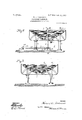
- Fig. 2 is a vertical sectional view-taken on Fig. 1.
- Fig. 3 is a vertical sectional view taken on the dotted Fig, 4 is across section of a portion of the track taken on the dotted showing the rear end of a car mounted on the track.
- Fig. 5 is a side elevation view of one of the cars adapted to be employed with my-invention, the view showing a portion of the track and its sup-- support being.
- Fi 6 is a side elevation view of the car propelling member in en agement with the member 32 of the car.
- ig. 7 is a horizontal sectional view dotted line. 41- of Fig. 1, showing one form of track brake employed.
- Fig. 9' is a vertical sectional view taken on the dotted line 76-1 .of- Fig.
- Fig. 10 is a cross section on the line mn of F g. 6. Similar characters of similar parts. I
- the endless track comprises two spiral portions each -of which encircles a vertical axis, the spirals being preferably volute spirals 1 and 2, preferablydisposed with the inner coilsgradually rising to the outer and upper convolutions'or coils.
- the ends of the spirals are connected by means of the track references denote and safely propelled around an endless track disposed so that the cars move at times at constantly accelerated speed and to diiferent altitudes, finally-returning by gravthe upper end of one spiral with the upper nd'of the other spiral, and the portion 3 connecting the lower end of onespiral with the lower endof the other spiral.
- tions of the volute spirals 1 and 2 preferably run in opposite directions, and the connectdenoted by 3 and 4',
- portions 3 and 4 the-portion 4 connecting The convolu- The saucer shaped supports 5 and are in turn supported by means of vertical posts 8 the lower endsof which are supported by any SilltfiblGlIlBflDS.
- the opening7 of the support 5 is not directly in the center, but is adjacent to the center, the central portion of the support 5 being employed as a landing place forthe passen ers, said central portion bein provided wit h'an openin 9 throughwhic the passengers may ascent? or 4 descend by means of stairs 10.
- the rails 11 of the track are preferabl mounted on a horizontal support 12 whic' in turn'is mounted on longitudinal stringers '13 mounted on'the upper sides of the saucer shapedsupports 5 and 6.
- a car or cars 14 are mounted secured to its under side between the forwar and rear wheels 15 an inverted U shaped bar, .the vertical arms of which project downward below and at opposite side edges of the support 12.
- On t e inner sides of the vertical arms of the U. bar 16 are rotativel mounted friction rollers 17 disposed below the support 12 and normally out of contact therewith. These rollers 17 prevent the'car from leaving the track.
- a vertical shaft 18 extends axially through the bottom of, the support 5, which support serves for. the u per bearing of said shaft, the lower end 0 the shaft being rotatively mounted in a vertical hole provided the horizontal Iplate 1? which is mounted on the ground. he shaft 18 is rotated by any suitable means.
- a motor such as an electric motor 20 having a driving shaft 21 on which is seon the track, each car having member 29 is zontal rotary shaft 225 mountedin bearings 26 and having secured -fto-it a screw 27 the threads of which mesh with the peripheral teeth of a worm gear wheel 28, said gear whee-l being secured on the driving shaft 18.
- the motor 20 is driven so as to rotate the shaft 18 contrary to a clockwise direction, as viewed in Fig. 1.
- a car engaging and propelling means is carried by the shaft 18.
- he preferable mechanism for this purpose comprises a vertical member 29 ri 1dly secured to the shaft 18 above the trac Said rovided with a curved arm 30 of channel. orm, the groove, denoted by 31 being in the lower side of the arm 30.
- the grooved arm 30 is curved so as to have its under side parallel with the u per side of the saucer shaped support 5. 8n the rear end of each car 14 is secured a vertical plate 32, which is curved at its upper end and side edges. The plate 32 is adapted to enter the groove 31 of the arm 30, and the car thereby be propelled by said arm when the shaft 18 is rotated in the proper direction.
- Fig. 8 is shown a brake provided between the rails of the spiral 1 by which the car may be stopped automatically soon after it enters the said spiral.
- This brake comprises an inclined lank 34, the lower end of which is pivoted between the stringers 13, the plank extending from its pilvotal point upwardly through a longitudinal slot 35 in the support 12.
- the upper end of the plank 34 is between the rails of the track and 8X- tends upwardly sufficiently to strike the underside of the car 14.
- a coil spring 36 has its lower end supported on the support 5, the up er end bearing upon the under side of the p ank 34 with sufficient pressure to stop the car when the car strikes and bears down the upper end of the lank 34.
- Fig. 9 is illustrated a. rakev similar to the one just described, the plank 3,4 in this brake being convex on its upper side. -nn
- suitable number of brakes corresponding to the one shown in Fig. 9 may be inserted at convenient laces between, the rails for the purpose of s ackening the speed of the cars-as they pass by gravity down the spiral portion 2 of the track.
- the curvature on the upper side of the plank 34 is for the purpose of etfering resistance to the passage of the cars without stopping them, the strength of the springs 36 supporting the planks 34 being only suflicient to retard but not stop the cars.
- the car will be propelled by means of the channel arm 30 so 'as to travel upward from the lower part of the spiral 1 to the up-' per end thereof.
- the plate or member 32 will travel lengthwise of the groove 31, so that by the time that the car reaches the upper and outer convolution of a the spiral 1, the plate or member 32 will be opposite the recessat the outer end of the arm 30, and the car will be free to pass from the spiral 1 along the connecting portion 4 of the track to theupper and outer convolution of the spiral portion 2 of the track.
- the car will then run in a reverse direction from the upper end of spiral 1 to the lower end thereof,
- the relative disposition of the plate 32 and inner end of the arm 30 may be such that when the car is stopped at the plank 34, the arm 30 will not engage the plate 32. i
- the car ma then be loaded or unloaded while over pla 34. After being loaded,.the caris to be pushed by hand along the lower coil of spiral 1 until it reaches a position in which the arm 30 will strike'the plate or member 32.
- arailway the combination with a track disposed in spiral coils around a vertical axis, of a vertical shaft disposed axially within said coils, means for rotating said shaft, and means carried by said shaft for engaging and propelling a car or cars upward along saidtrack.
- I11 a railway, the combinationwith a saucer shaped support having an opening adjacent thecenter, of a volute formed tracx mounted on said'support, the lower inner -coil of the volute extending through said opening, a car mounted on said track, and
- an endless track formed in two spirals encircling two vertical axes, the upper and lower ends of one spiral connecting respectively with the upper and lower ends of the other spiral.
- an endless track comprising two volute spirals encircling vertical axes, the ends of one spiral connecting with ends of the other spiral.
- an endless track comprising two volute spirals encircling vertical axes, the convolutions of the spirals running in opposite directions, the track'in each spiral rising from the inner to the outer coil or con.- volution, the track having crossed portions connecting respectively the ends of one spiral with the ends of the other s 'iral.
- the track having crossed portions connecting mounted in one spiral, and car engagigg and propelling means connected with s shaft said supports, and the track having portions connecting the ends of one spiral respectively with the ends of the other spiral.
- the combination with two saucer shaped supports each having an opening adjacent its central bottom portion, of an endless track comprising two volute spirals mounted respectively upon said sup-' ports, the lower ends of the spirals extend ing respectively through said openings, the
- a railway the combination with track comprising two volute spirals mounted on said supports respectively, the lower ends of said spirals extending through said openings respectively, .thetrack having portions connecting the ends of one spiral with the endsof the otherspiral, an axial rotary shaft in one of said spirals, means for rotating said,
- the combination with an endless track comprising two volute spirals encircling verticalaxes, the track having portions connecting the ends-of one spiral with the ends of the other spiral, of car engaging and propelling means rotatable around the axis of one spiral, and speed controlling means located adjacent the track in the other spiral and provided with means for engaging a car and reducing the speed thereof.
- the combmation with an endless track comprising two volute spirals encircling vertical axes, the track 7 having ortions connecting the-ends of one spiral w th the ends of the other spiral, of a v 39.
- the combmation'with s aftdisposed axially in onespiral, means for rotating said shaft, a member secured to said shaft and having an arm extending transversely over the coils of the adjacent spiral, and a canon said tracli and provided with a member adapted to be en aged by said arm, whereby the car is prope ed along the coils of the spiral adjacent to said arm when the shaft is rotated.
- the combination with an endless track comprising two volute spirals encircling vertical axes, the track having portions connecting the ends of one s iral -w1th the ends of the other spiral, of a s aft disposed, axially in oneispiral, means for rotating said shaft, a member secured to said shaft having an arm extending across the coils of the adjacent spiral, the armhaving a'longitudinal groove on its under side, and i a car on said track having a member adapted to enter "said oove and travel lengthwise therein when t e car is propelled along the track by said arm.
Landscapes
- Train Traffic Observation, Control, And Security (AREA)
Description
B? T COPY PATENTED JAN. 21, 1908.
3 SHEETS-SHEET 1.
Inumth:
No. 877,100. PATENTEDJAN.21,1908. .H. A. LOOKWOOD.
PLEASURE RAILWAY.
APPLICATION FILED JAN. 24, 1907.
a SHEET8-SHEET 2.
v v fimnmtfi: witnesses: -Mmw 152/54 attorney, i 43 M m 110,877,100. PATENTED JAN. 21, 1908.
H. A. LOGKWOOD.
PLEASURE RAILWAY.
APPLICATION FILED 3111.24, 1907.
3 SHEBTS-SHEET 3.v
Ilnmntut witnesfiesz 159% lttume Q 7 fl M WWW rapidly line c-d of Fig. 1.
.the dotted line (Lfib of line ef of Fig, 5, and
HORACE AILOCKWOOD, OF KANSAS CITY, MISSOURI.
PLEASURE-RAILWAY.
Specification of Letters Patent.
Patented Jan. 21, 1908.
I Application filed nuuar zi. 1907. Seria1No. 353.798.
To all whom'it mag/concern:
Be it known that I, HORACE A. LooK- WOOD, a citizen of the United States, residing at Kansas City, in the county of Jackson and State of Missouri, have invented certain new and useful Improvements in Pleasure- Railways, of which the following is a specification. 1
My invention relates to improvements in pleasure railways. I
The object of my invention is to provide a pleasure railway in which the cars may be ity to the starting point.
The novel features of my invention are hereinafter fully described and claimed. a
- In the accompanying drawings illustrative Fig. 2 is a vertical sectional view-taken on Fig. 1. Fig. 3 is a vertical sectional view taken on the dotted Fig, 4 is across section of a portion of the track taken on the dotted showing the rear end of a car mounted on the track. Fig. 5 is a side elevation view of one of the cars adapted to be employed with my-invention, the view showing a portion of the track and its sup-- support being.
port, a portion of the track shown in vertical section. Fi 6 isa side elevation view of the car propelling member in en agement with the member 32 of the car. ig. 7 is a horizontal sectional view dotted line. 41- of Fig. 1, showing one form of track brake employed. Fig. 9' is a vertical sectional view taken on the dotted line 76-1 .of- Fig.
1,. showing another form of track brake employed. Fig. 10 is a cross section on the line mn of F g. 6. Similar characters of similar parts. I
The endless track comprises two spiral portions each -of which encircles a vertical axis, the spirals being preferably volute spirals 1 and 2, preferablydisposed with the inner coilsgradually rising to the outer and upper convolutions'or coils. The ends of the spirals are connected by means of the track references denote and safely propelled around an endless track disposed so that the cars move at times at constantly accelerated speed and to diiferent altitudes, finally-returning by gravthe upper end of one spiral with the upper nd'of the other spiral, and the portion 3 connecting the lower end of onespiral with the lower endof the other spiral.
tions of the volute spirals 1 and 2 preferably run in opposite directions, and the connectdenoted by 3 and 4',
ing portions of the track The spirals 1 therefore, cross each other.
and 2 are mounted'preferably upon the upper sides of two saucer shaped supports 5 and 6 provided each adjacent its center with arr-opening 7 through which the track extends at the lower end of the adjacent spiral portion. 6 are formed of any suitable material, and
portions 3 and 4:, the-portion 4 connecting The convolu- The saucer shaped supports 5 and are in turn supported by means of vertical posts 8 the lower endsof which are supported by any SilltfiblGlIlBflDS. -The opening7 of the support 5 is not directly in the center, but is adjacent to the center, the central portion of the support 5 being employed as a landing place forthe passen ers, said central portion bein provided wit h'an openin 9 throughwhic the passengers may ascent? or 4 descend by means of stairs 10.
" The rails 11 of the track are preferabl mounted on a horizontal support 12 whic' in turn'is mounted on longitudinal stringers '13 mounted on'the upper sides of the saucer shapedsupports 5 and 6. A car or cars 14 are mounted secured to its under side between the forwar and rear wheels 15 an inverted U shaped bar, .the vertical arms of which project downward below and at opposite side edges of the support 12. On t e inner sides of the vertical arms of the U. bar 16 are rotativel mounted friction rollers 17 disposed below the support 12 and normally out of contact therewith. These rollers 17 prevent the'car from leaving the track.-
A vertical shaft 18 extends axially through the bottom of, the support 5, which support serves for. the u per bearing of said shaft, the lower end 0 the shaft being rotatively mounted in a vertical hole provided the horizontal Iplate 1? which is mounted on the ground. he shaft 18 is rotated by any suitable means. 'For this purpose I have illustrated a motor, such as an electric motor 20 having a driving shaft 21 on which is seon the track, each car having member 29 is zontal rotary shaft 225 mountedin bearings 26 and having secured -fto-it a screw 27 the threads of which mesh with the peripheral teeth of a worm gear wheel 28, said gear whee-l being secured on the driving shaft 18. The motor 20 is driven so as to rotate the shaft 18 contrary to a clockwise direction, as viewed in Fig. 1. A car engaging and propelling means is carried by the shaft 18. he preferable mechanism for this purpose comprises a vertical member 29 ri 1dly secured to the shaft 18 above the trac Said rovided with a curved arm 30 of channel. orm, the groove, denoted by 31 being in the lower side of the arm 30.
The grooved arm 30 is curved so as to have its under side parallel with the u per side of the saucer shaped support 5. 8n the rear end of each car 14 is secured a vertical plate 32, which is curved at its upper end and side edges. The plate 32 is adapted to enter the groove 31 of the arm 30, and the car thereby be propelled by said arm when the shaft 18 is rotated in the proper direction.
As shown in Fig. (5, the arm 30-at opposite ends has recesses 33 provided in the forward side of the channel. These recesses 33 permit the plate 32 to enter and leave the groove 31 of the arm 30 while the shaft 18 -is rotat-' 1n ln Fig. 8 is shown a brake provided between the rails of the spiral 1 by which the car may be stopped automatically soon after it enters the said spiral. This brake comprises an inclined lank 34, the lower end of which is pivoted between the stringers 13, the plank extending from its pilvotal point upwardly through a longitudinal slot 35 in the support 12. The upper end of the plank 34 is between the rails of the track and 8X- tends upwardly sufficiently to strike the underside of the car 14. y A coil spring 36 has its lower end supported on the support 5, the up er end bearing upon the under side of the p ank 34 with sufficient pressure to stop the car when the car strikes and bears down the upper end of the lank 34.
In Fig. 9 is illustrated a. rakev similar to the one just described, the plank 3,4 in this brake being convex on its upper side. -nn
suitable number of brakes corresponding to the one shown in Fig. 9 may be inserted at convenient laces between, the rails for the purpose of s ackening the speed of the cars-as they pass by gravity down the spiral portion 2 of the track. The curvature on the upper side of the plank 34 is for the purpose of etfering resistance to the passage of the cars without stopping them, the strength of the springs 36 supporting the planks 34 being only suflicient to retard but not stop the cars. a a
In. operating my invention, the car while being held by the brake plank 34 at the lower part of spiral portion 1 is loaded withpassen- 'gers. The motor 20 is then started, thus brake plank 34, will enter the recess 33 adj a.
cent the shaft 18. As the shaft 18 continues to rotate the car will be propelled by means of the channel arm 30 so 'as to travel upward from the lower part of the spiral 1 to the up-' per end thereof. As the car passesaround the convolutions of the-spiral 1,'the plate or member 32 will travel lengthwise of the groove 31, so that by the time that the car reaches the upper and outer convolution of a the spiral 1, the plate or member 32 will be opposite the recessat the outer end of the arm 30, and the car will be free to pass from the spiral 1 along the connecting portion 4 of the track to theupper and outer convolution of the spiral portion 2 of the track. The car will then run in a reverse direction from the upper end of spiral 1 to the lower end thereof,
and thence bythe track portion 3 to the lower end of spiral portion 1', passing through the opening? of support 5, and along the.
lower inner coil of spiral 1 to the brake plank 34, at which place the car is stopped. The relative disposition of the plate 32 and inner end of the arm 30 may be such that when the car is stopped at the plank 34, the arm 30 will not engage the plate 32. i The car ma then be loaded or unloaded while over pla 34. After being loaded,.the caris to be pushed by hand along the lower coil of spiral 1 until it reaches a position in which the arm 30 will strike'the plate or member 32.
As the car passes upward along the spiral portion 1 of the track it will have its speed The car passing from the larger to the smaller I coils in spiral 2 will, if the inclination be not too great, have its speed reduced by track frict on.
Having thus described my invention, what gradually and constantly accelerated until it I claim and desire to secure by Letters Patent, is i 1. In a railway, the combination with a track disposed in coils arran ed in volute form, of-a rotary shaft dispose axially within said coils, and means carried by said shaft for engaging and propelling a car 'or cars along said track.
2. In a railway, thecombination with a track disposed in coils arranged in volute form, the track gradually rising from the inner to the outer coil, of'a rotary shaft disposed axially within said coils, and means carried by said shaft for engaging and propclling a car or cars along said track.
3. ln a railway, the combination with a track disposedin coils arranged in volute form, of rotating means for engaging and propelling a car or cars along said track.
4. In a railway, the combination with a track disposed in coils arranged in volute form, the track gradually rising from the inner to the outer coil, of rotating nieans for. engaging and propelling a car or cars along said track.
5. In arailway, the combination with a track disposed in spiral coils around a vertical axis, of a vertical shaft disposed axially within said coils, means for rotating said shaft, and means carried by said shaft for engaging and propelling a car or cars upward along saidtrack.
6. In a railway, the combination with a track disposed in coils arranged spirally around a vertical axis, of a rotary vertical shaft disposed axially in said coils, and a member carried by said shaft and extending transversely across said track and having means for engaging and propelling acar along saidtrack.
7. Ina railway, track disposed in coils form, of a rotary vertical shaft disposed axially in said coils, and a member carried by said shaft and extending across said coils and adapted to engage and propela car along said track.
9. In a railway, the combination with a track disposed in coils arranged in volute form, of a rotary shaft disposed vertically and axially in said coils, a car on said track having a vertical member secured thereto, and a member carried by the said shaft and provided with a grooved portion extending across said coils and adapted to receive therein said member attached to said car, whereby the car may be engaged and proelled by the member carried byt-he shaft when the. shaft is revolved.
10. In a railway, the combination with a saucer shaped support havingan opening adjacent the center, of a volute formed track mounted on said support, one end of the track extending through said opening, the track rising gradually frc :11 said opening to the outer coil of the volute.
11. I11 a railway, the combinationwith a saucer shaped support having an opening adjacent thecenter, of a volute formed tracx mounted on said'support, the lower inner -coil of the volute extending through said opening, a car mounted on said track, and
the combination with a arranged in volute tively two vertical axes,
, the other spiral,
means for engaging saidcar and propelling'it upwardly along said track.
' 12. In a railway, the combination with a saucer shaped support, of a track mounted on said supportand dis osed incoils arranged.
in volute form, asha' t disposed axially in said coils, means for rotating said shaft, acar on said track, and means carried by said' shaft for engaging along the track when the shaft is rotated.
13. In a railway, the combination with a saucer shaped support, of a track disposedin coils arranged in voluteiform upon said support, a shaft disposed axially in said-coils, means for rotating said shaft, a canon said track, and a member secured to the shaft and extending across said coils and having means for engaging and propelling the car along the track when the shaft is rotated.
-14;. In a railway, the combination with a coils arranged in volute form upon said support, a shaft disposed axially in said coils,
-means for rotating said shaft, a car on said track having a member secured thereto, and
an arm secured to said shaft and extending across said coils and provided on its under side with a groove disposed transversely to the track and adapted to receive therein the member on the car, whereby the car may be propelled when the shaft is rotated.
15. In a railway, an endless track formed in two spirals encircling two vertical axes, the upper and lower ends of one spiral connecting respectively with the upper and lower ends of the other spiral.
16. In a railway, an endless track comprising two volute spirals encircling vertical axes, the ends of one spiral connecting with ends of the other spiral.
1 7. In a railway,an endless track comprising twovolute spirals encircling respecthe track in each spiral rising gradually from the inner to the outer coil, the upper and lower ends of one spiral connecting respectively with the upper and lower ends of the other spiral.
18. In a railway, the combination with an endless track formed in two spirals encircling vertical axes, the upper and lower ends ofone spiral connecting with corresponding and propelling the car saucer shaped support, of a track disposed in a ios ends of the otherspiral, of women said track,
and means for propelling said car along the track from the lower to the upper end of one of said spirals.
19. In a railway, the combination with an endless track formed in two spirals encircling vertical axes, the upper and lower ends of one spiral connecting with corresponding ends of of a caron said. track, an axial shaft located in one spiral, means for rotating said shaft, and means connected with said shaft for engaging and propelling said car on the adjacent spiral portion of the' track when the shaft is rotated.
20. Ina railway, the combination with an endless track formed in two spirals encircling vertical axes, the npper'and lower ends of one spiral connecting w th corresponding ends of the other spiral, of an. axial rotary shaft lo-v cated in one spiral, and car engaging and propelling means carried by said shaft.
21. In a railway, the combination with an endless track formed in two spirals encircling vertical axes, the upper and lowerends of one spiral connecting with corresponding ends of the other spiral, ofa car'onsaid track, and car engaging means rotative around the axis of one of the spirals.
' 22. In a railway, the combination with an endless track formed in two spirals encircling vertical axes, the upper and lower ends of one spiral connecting respectively with corresponding ends of the other spiral, of an axial shaft located in one spiral, means for rotat.
- ing said shaft and car engaging means car'- ried by said shaft,
23. In a railway, the combination with an endless track formed in two volute spirals encircling vertical axes, the ends of one spiral connecting respectivelyiwith the ends of the other spiral, of a car on said track, and
means for propelling the car'along the track from the lower to the upper end of one of 30,
said spirals.
24. In a railway, thecombination' with an endless track formed in two spirals encircling vertical axes, the ends ofone spiral connecting respectively with the endsof the. other spiral, of avrotaryaxial shaft locatedin one of said spirals,'and car engaging means carried by said shaft. I
25. In a railway, the combination with an endless track formed in two spirals encircling vertical axes, the ends of one spiral connecting respectively with the ends of the other spiral, of an axial shaft located in one spiral,
means for rotating said shaft, and an arm.
carried by said shaft and having means for engaging and propelling a car along the track when the shaft is rotated.
26. In a'railway, the combination with an endless track formed in two volute spirals encircling vertical axes, the ends of one spiral connecting respectively with the ends of the other spiral, of car engaging and propelling means rotative around the axis of one of said spirals.
{by said shaft and extending transversely across the co ils of one volute spiral.
In a railway, the combination with an endless track formedin two volute spirals encirclingvertical axes, the track in eachspiralrising from the inner to the outer coil, and
rotatively and axially mounted in one spiral, and car engaging and propelling means carried by said shaftand extending transversely across the coils of the adjacent spiral.
29. In a railway, an endless track con1 prising two volute spirals encircling vertical axes, gthe convolutions of the spirals running in opposite directions-around said axes, and the ends of one s iral connecting respectively with the ends 0 .thejother s iral.
30. In a railway, an end ess track corn- I prising two volute spirals encirclingvertical axes,'the convolutions of the spirals running in opposite directions, the track in said spirals rising from the inner to the outer coils, and
the ends. of one s iral connecting respectively with the ends 0 the other s iral.
31. In a railway, anen ess trackcomprising two volute spirals encircling vertical axes, the convolutions of the spirals running in opposite directions, the track having crossed portions connecting respectively the ends of one spiral with the ends of the other spiral. I
Ina railway, an endless track comprising two volute spirals encircling vertical axes, the convolutions of the spirals running in opposite directions, the track'in each spiral rising from the inner to the outer coil or con.- volution, the track having crossed portions connecting respectively the ends of one spiral with the ends of the other s 'iral.
33.. In a railway, the com ination with an endless track comprising two volute spirals encircling vertical axes, the convolutions-of the spirals running in opposite directions, the track having crossed portions connecting respectively the ends of one spiral with the ends of the other spiral, ofnieans for engaging and propelling acar alongthe track from I the lower end to the upper end ofv one'spi'ral. 341 In a railway, the combination with an endless track com rising two volute spirals portions connecting-the ends of one s iral -.encircling vertica axes, the track having with the ends of the other spiral, of as aft rotatively and axiallymounted in one spiral,
and means carried by said shaft for engaging and'propelling a car along the track from, the lower end of one spiral to the upper end thereof.
' 35. In a railway, the-combination with an endless track comprising two volute spirals encircling vertical axes, the convolntio'ns of the spirals running 111 opposite, directions,
the track having crossed portions connecting mounted in one spiral, and car engagigg and propelling means connected with s shaft said supports, and the track having portions connecting the ends of one spiral respectively with the ends of the other spiral.
' 37 In a railway, the combination" with two saucer shaped supports each having an opening adjacent its central bottom portion, of an endless track comprising two volute spirals mounted respectively upon said sup-' ports, the lower ends of the spirals extend ing respectively through said openings, the
track having a portion connecting the lower ends of the spirals and a portion connecting the upper ends of the spirals.
38. ,In a railway, the combination with two-saucershaped supports each having an opening adjacent its central bottom portion,
of an endless track '-comprising two yolute' spirals mounted respectively upon saidsup ports, the lower ends of the. spirals extending respectively through said openings, the
track having portions connecting the ends of one spiral with theends 0f the other spiralf and means for engaging and propellinga car along the track from the lower to the upper end of one of said spiral portions of said"- track.
two saucer-shaped supports having each an opening adjacent its central'portion, of an endless track comprising two volute spiral portions mounted on said supports respectively, the-lower'endsof the spirals extendtwo saucer shaped supports each having anopening adjacent its center, of an endless ing through said openings", the track'having portions. connecting vthe ends of onefs'pira portionwith the ends of the otherspiral portion, a shaft disposed axially in one spiral,
means for rotat ngsaid shaft, and means connected with said shaft for engaging and,
ropelling a car along thetrack from the ower end to the upperend of one of the spiral ortions of the track.
40. n a railway, the combination with track comprising two volute spirals mounted on said supports respectively, the lower ends of said spirals extending through said openings respectively, .thetrack having portions connecting the ends of one spiral with the endsof the otherspiral, an axial rotary shaft in one of said spirals, means for rotating said,
shaft, and a member secured to said shaft and extending transversely across the coils of the adjacentspiral and provided with means for engpg'ing and ropellin a car along the trac from'the ower en .to the for engaging and propelling the car along the track when. the shaft is rotated, and means independent of said car engaging means for controlling the speed of movement of the car.
42..' In a railway, the combination with an endless .track comprisin 'two volutespirals encircling vertical axes, t e track having por tions connecting the ends of one spiral with the ends of the other spiral, of means for en gaging and propelling acar alon ;-the track from the lower to the upper end 0 one spiral,
and means for controlling the speed of the car around the coils of the other spiral.
43. In a railway, the combination with an endless track comprising two volute spirals encircling verticalaxes, the track having portions connecting the ends-of one spiral with the ends of the other spiral, of car engaging and propelling means rotatable around the axis of one spiral, and speed controlling means located adjacent the track in the other spiral and provided with means for engaging a car and reducing the speed thereof. 44. Ina railway, the combmation with an endless track comprising two volute spirals encircling vertical axes, the track 7 having ortions connecting the-ends of one spiral w th the ends of the other spiral, of a v 39. In a railway, the combmation'with s aftdisposed axially in onespiral, means for rotating said shaft, a member secured to said shaft and having an arm extending transversely over the coils of the adjacent spiral, and a canon said tracli and provided with a member adapted to be en aged by said arm, whereby the car is prope ed along the coils of the spiral adjacent to said arm when the shaft is rotated.
45. In a railway, the combination with an endless track comprising two volute spirals encircling vertical axes, the track having portions connecting the ends of one s iral -w1th the ends of the other spiral, of a s aft disposed, axially in oneispiral, means for rotating said shaft, a member secured to said shaft having an arm extending across the coils of the adjacent spiral, the armhaving a'longitudinal groove on its under side, and i a car on said track having a member adapted to enter "said oove and travel lengthwise therein when t e car is propelled along the track by said arm.-
46. In a railway, an endless track'com prising two volute spirals, the convolutions running in o po'site directions,-.the upper and lower en s on one spiral connecting respectively with corresponding ends of the other s iral.,
' 47. a railway, the combination with an endless 'ti'ack comprising twovolute spirals, vname to this specification in presence of two 'the convolutions ofwhich 11min opposite subscribing witnesses. Y
directlons, and the upper and lower ends of onespiralconnecfingw th correspondingends E LOOKWVOOD" 5 of the other spiral, of a car propellin means Witnesses:
for propelling the car alon the trac E. B. HOUSE,
In testimony whereof havesigned my R E. HAMIL ON.
Priority Applications (1)
| Application Number | Priority Date | Filing Date | Title |
|---|---|---|---|
| US35379807A US877100A (en) | 1907-01-24 | 1907-01-24 | Pleasure-railway. |
Applications Claiming Priority (1)
| Application Number | Priority Date | Filing Date | Title |
|---|---|---|---|
| US35379807A US877100A (en) | 1907-01-24 | 1907-01-24 | Pleasure-railway. |
Publications (1)
| Publication Number | Publication Date |
|---|---|
| US877100A true US877100A (en) | 1908-01-21 |
Family
ID=2945545
Family Applications (1)
| Application Number | Title | Priority Date | Filing Date |
|---|---|---|---|
| US35379807A Expired - Lifetime US877100A (en) | 1907-01-24 | 1907-01-24 | Pleasure-railway. |
Country Status (1)
| Country | Link |
|---|---|
| US (1) | US877100A (en) |
-
1907
- 1907-01-24 US US35379807A patent/US877100A/en not_active Expired - Lifetime
Similar Documents
| Publication | Publication Date | Title |
|---|---|---|
| JPS63150089A (en) | Track structure of play track running vehicle apparatus | |
| US792422A (en) | Pleasure-railway. | |
| JP2008168135A (en) | Amusement device, vehicle for amusement device and operating method for amusement device | |
| US872253A (en) | Amusement apparatus. | |
| US877100A (en) | Pleasure-railway. | |
| JPS61154690A (en) | Track structure for vehicle of jet coarster receiving passenger | |
| US637005A (en) | Elevated railway. | |
| US1074185A (en) | Pleasure-railway. | |
| US433941A (en) | Aerial-railway transit | |
| US1311703A (en) | Pleasure-raid way | |
| US2080029A (en) | Amusement apparatus | |
| JPS6344076Y2 (en) | ||
| US468553A (en) | Sliding hill or chute for carriages | |
| US318026A (en) | Artificial coasting-course | |
| US716285A (en) | Amusement apparatus. | |
| US309689A (en) | Tramway and car | |
| US1107287A (en) | Amusement device. | |
| US757487A (en) | Roller-coaster. | |
| US2109041A (en) | Amusement apparatus | |
| US1150245A (en) | Roundabout. | |
| US902073A (en) | Amusement apparatus. | |
| US900000A (en) | Conveyer. | |
| US325386A (en) | bliyen | |
| US880040A (en) | Pleasure-railway. | |
| US315992A (en) | Cable eailway |