US8770717B2 - Image forming apparatus including carriage that mounts image forming unit - Google Patents
Image forming apparatus including carriage that mounts image forming unit Download PDFInfo
- Publication number
- US8770717B2 US8770717B2 US13/213,352 US201113213352A US8770717B2 US 8770717 B2 US8770717 B2 US 8770717B2 US 201113213352 A US201113213352 A US 201113213352A US 8770717 B2 US8770717 B2 US 8770717B2
- Authority
- US
- United States
- Prior art keywords
- portions
- engagement
- carriage
- image forming
- drawing member
- Prior art date
- Legal status (The legal status is an assumption and is not a legal conclusion. Google has not performed a legal analysis and makes no representation as to the accuracy of the status listed.)
- Expired - Fee Related, expires
Links
Images




Classifications
-
- B—PERFORMING OPERATIONS; TRANSPORTING
- B41—PRINTING; LINING MACHINES; TYPEWRITERS; STAMPS
- B41J—TYPEWRITERS; SELECTIVE PRINTING MECHANISMS, i.e. MECHANISMS PRINTING OTHERWISE THAN FROM A FORME; CORRECTION OF TYPOGRAPHICAL ERRORS
- B41J19/00—Character- or line-spacing mechanisms
- B41J19/005—Cable or belt constructions for driving print, type or paper-carriages, e.g. attachment, tensioning means
-
- B—PERFORMING OPERATIONS; TRANSPORTING
- B41—PRINTING; LINING MACHINES; TYPEWRITERS; STAMPS
- B41J—TYPEWRITERS; SELECTIVE PRINTING MECHANISMS, i.e. MECHANISMS PRINTING OTHERWISE THAN FROM A FORME; CORRECTION OF TYPOGRAPHICAL ERRORS
- B41J19/00—Character- or line-spacing mechanisms
- B41J19/14—Character- or line-spacing mechanisms with means for effecting line or character spacing in either direction
- B41J19/142—Character- or line-spacing mechanisms with means for effecting line or character spacing in either direction with a reciprocating print head printing in both directions across the paper width
Definitions
- This disclosure relates to an image forming apparatus, and more specifically to an image forming apparatus including a carriage that mounts an image forming unit.
- Image forming apparatuses are used as printers, facsimile machines, copiers, plotters, or multi-functional devices having two or more of the foregoing capabilities.
- an inkjet recording apparatus uses a recording head (liquid-droplet ejection head) for ejecting droplets of ink.
- a recording head liquid-droplet ejection head
- Such liquid-ejection-type image forming apparatuses eject droplets of ink or other liquid from the recording head onto a recording medium to form a desired image.
- a serial-type image forming apparatus As one sub type of such liquid-ejection-type image forming apparatus, a serial-type image forming apparatus is known that has a carriage mounting the recording head (liquid ejection head) serving as an image forming unit. Such a serial-type image forming apparatus forms an image by ejecting droplets from the recording head while moving the carriage mounting the recording head in a main scanning direction and intermittently feeding the recording medium in a sub-scanning direction perpendicular to the main scanning direction.
- the image forming unit is described below as the liquid ejection head, the image forming unit is not limited to the liquid ejection head and may be any other type of image forming unit.
- Such a serial-type image forming apparatus typically has a main scanning mechanism (carriage scanning mechanism) to move the carriage mounting the image forming unit for scanning in the main scanning direction.
- the main scanning mechanism includes a driving source, a driving pulley mounted to the driving source, a driven pulley driven by rotation of the driving pulley, and an endless timing belt extended between the driving pulley and the driven pulley and serving as a carriage drawing member to draw the carriage partially fixed on the timing belt.
- a long-size timing belt is used as the drawing member and the carriage moves a relatively long distance during main scanning. Because a long-size endless belt compatible with image formation on large-width media costs much, it is conceivable to use an open-ended belt (i.e., belt having ends) instead of the endless belt.
- the tension applied to the belt need be increased to stably perform the main scanning of the carriage.
- end portions of the open-ended belt need be more firmly set to the carriage.
- the number of teeth of the belt is determined by the distance between the driving source (driving motor) and the driven pulley, and the tension of the belt is determined by the number of teeth. If the mount position of the belt to the carriage is shifted in installation, the number of teeth of the belt is changed, thus hampering application of a desired tension to the belt.
- an image forming apparatus including a carriage, an image forming unit, a driving pulley, a driven pulley, a driving source, an open-ended carriage drawing member, and a mount.
- the carriage is movably supported to move reciprocally in a main scanning direction.
- the image forming unit is mounted on the carriage to form an image.
- the driving pulley is disposed at a first end in the main scanning direction.
- the driven pulley is disposed at a second end opposite the first end in the main scanning direction.
- the driving source is operatively connected to the driving pulley to rotate the driving pulley.
- the open-ended carriage drawing member is extended between the driving pulley and the driven pulley and having end portions mounted to the carriage, each of the end portions having a surface at least partially including an indented area.
- the mount is disposed on the carriage to mount the end portions of the drawing member and having first engagement portions and second engagement portions.
- Each of the first engagement portions has at least one indented area to engage the indented area of a corresponding one of the end portions of the drawing member.
- Each of the second engagement portions is connected to a corresponding one of the first engagement portions in an orientation to be folded back relative to the corresponding first engagement portion.
- the end portions of the drawing member are mounted to the mount of the carriage in a state in which the surface of each of the end portions having the indented area to engage a corresponding one of the first engagement portions is directed to a fold-back portion of each of the end portions folded back along a corresponding one of the second engagement portions relative to the corresponding one of the first engagement portions.
- FIG. 1 is a perspective view of an inkjet recording apparatus as an image forming apparatus according to an exemplary embodiment of this disclosure
- FIG. 2 is a perspective view of a carriage scanning mechanism of the inkjet recording apparatus illustrated in FIG. 1 ;
- FIG. 3 is a front view of a belt mount of a carriage in a first exemplary embodiment in a state in which a timing belt is mounted to the belt mount;
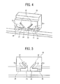
- FIG. 4 is a perspective view of the belt mount of the carriage of FIG. 3 ;
- FIG. 5 is a front view of the belt mount of the carriage of FIG. 3 ;
- FIG. 6 is a front view of a belt mount of a carriage in a second exemplary embodiment
- FIG. 7 is a front view of a belt mount of a carriage in a third exemplary embodiment
- FIG. 8 is an enlarged front view of a belt mount of a carriage in a fourth exemplary embodiment
- FIG. 9 is a further enlarged front view of the belt mount illustrated in FIG. 8 ;
- FIG. 10 is a perspective view of a belt mount of a carriage in a fifth exemplary embodiment
- FIG. 11 is a front view of the belt mount of the carriage illustrated in FIG. 10 ;
- FIG. 12 is a cross-sectional view of the belt mount of the carriage illustrated in FIG. 10 ;
- FIG. 13 is a front view of a belt mount of a carriage in a sixth exemplary embodiment in a state in which a timing belt is mounted to the belt mount.
- image forming apparatus of liquid ejection type refers to an apparatus that ejects ink or any other liquid on a medium to form an image on the medium.
- the medium is made of, for example, paper, string, fiber, cloth, leather, metal, plastic, glass, timber, and ceramic.
- image formation which is used herein as a synonym for “image recording” and “image printing”, includes providing not only meaningful images such as characters and figures but meaningless images such as patterns to the medium.
- image recording which is used herein as a synonym for “image recording” and “image printing”, includes providing not only meaningful images such as characters and figures but meaningless images such as patterns to the medium.
- the term “ink” as used herein is not limited to “ink” in a narrow sense and includes anything useable for image formation, such as recording liquid, fixing solution, liquid, and resin.
- sheet used herein is not limited to a sheet of paper and includes anything such as an OHP (overhead projector) sheet or a cloth sheet on which ink droplets are attached.
- OHP overhead projector
- sheet is used as a generic term including a recording medium, a recorded medium, a recording sheet, and a recording paper sheet.
- image used herein is not limited to a two-dimensional image and includes, for example, an image applied to a three dimensional object and a three dimensional object itself formed as a three-dimensionally molded image.
- an inkjet recording apparatus is described as an image forming apparatus according to an exemplary embodiment of this disclosure with reference to FIGS. 1 and 2 .
- FIG. 1 is a perspective view of an entire configuration of the inkjet recording apparatus.
- FIG. 2 is a perspective view of a carriage scanning mechanism of the inkjet recording apparatus.
- the inkjet recording apparatus is a serial-type inkjet recording apparatus and has a main unit 1 and a support stand 2 to support the main unit 1 .
- the main unit 1 includes a guide rod 3 and a guide stay 4 that are extended between side plates.
- a carriage 5 is supported with the guide rod 3 and the guide stay 4 so as to be slidable along a main scanning direction indicated by an arrow A in FIG. 1 .
- the guide rod 3 serves as a carriage guide member to guide movement of the carriage 5 along the main scanning direction
- the guide stay 4 serves as a support member to support the guide rod 3 .
- recording heads 6 serving as liquid-ejection-type image forming unit for ejecting ink droplets of, for example, black (K), yellow (Y), magenta (M), and cyan (C).
- the recording heads 6 are integrally provided with head tanks that supply inks to the recording heads.
- the image forming unit is described as liquid ejection head in this exemplary embodiment, the image forming unit is not limited to the liquid ejection head and may be any other type of image forming unit.
- a main scanning unit 10 for moving the carriage 5 for scanning includes a driving motor 11 serving as a driving source disposed at one end in the main scanning direction, a driving pulley 12 rotated by the driving motor 11 , a driven pulley 13 disposed at the opposite end in the main scanning direction, and a timing belt 14 serving as an open-ended carriage drawing member extended between the driving pulley 12 and the driven pulley 13 .
- a tension spring urges the driven pulley 13 outward (in a direction to move away from the driving pulley 12 ) to apply tension to the timing belt 14 .
- a suction conveyance unit 7 In a recording area of a main scanning region of the carriage 5 , a suction conveyance unit 7 intermittently conveys a sheet 20 in a direction (sub-scanning direction or sheet conveyance direction) indicated by an arrow B in FIG. 1 .
- a maintenance-and-recovery unit 8 At one end of the main scanning region is disposed a maintenance-and-recovery unit 8 to maintain and recover good conditions of the recording heads 6 .
- main cartridges 9 serving as main tanks are removably mounted to the main unit 1 to store color inks supplied to the head tanks of the recording heads 6 .
- a roll sheet 20 (hereinafter, “sheet 20 ”) is set on a sheet feeder 21 .
- a roll sheet of a different width can be set on the sheet feeder 21 .
- the sheet 20 fed from the sheet feeder 21 is conveyed with a conveyance device from a rear side to a front side of the apparatus to reach the recording area.
- the inkjet recording apparatus ejects droplets from the recording heads 6 in accordance with image information to form a desired image on the sheet 20 .
- the sheet 20 is cut at a desired length and discharged to a discharge tray at the front side of the inkjet recording apparatus.
- FIG. 3 is a front view of a belt mount of a carriage in the first exemplary embodiment in a state in which the timing belt is mounted on the belt mount of the carriage.
- FIG. 4 is a perspective view of the belt mount of the carriage illustrated in FIG. 3 .
- FIG. 5 is a front view of the belt mount of the carriage illustrated in FIG. 3 .
- a belt mount 30 serving as a drawing-member mount unit on which end portions 14 A and 14 B of the open-ended timing belt 14 serving as the open-ended carriage drawing member are mounted.
- the belt mount 30 has first engagement portions 31 with indented areas 31 a to engage indented areas 14 a of the timing belt 14 and second engagement portions 32 oriented so that the direction in which each of the second engagement portions 32 extends intersects the direction in which the corresponding one of the first engagement portions 31 extends.
- the first engagement portions 31 are formed along the main scanning direction
- the second engagement portions 32 are formed so as to sharply fold back relative to the main scanning direction (the direction in which the first engagement portions 31 extend).
- the second engagement portions 32 have grooves to engage the timing belt 14 .
- the second engagement portions 32 have a length L (see FIG. 5 ) of an integral multiple of an indentation pitch of the indented areas 14 a of the timing belt 14 .
- L see FIG. 5
- the number of teeth of the timing belt 14 relative to the distance between the driving source (driving motor 11 ) and the driven pulley 13 can be fixed at a certain number, thus obtaining desired belt tension.
- the first engagement portions 31 may also be oriented at a desired angle relative to the main scanning direction.
- Guide portions 33 are disposed between the first engagement portions 31 and the second engagement portions 32 to guide the timing belt 14 from the second engagement portions 32 to the first engagement portions 31 .
- a portion between the guide portions 33 serves as a partition to divide the end portions 14 A and 14 B of the timing belt 14 .
- each first engagement portion 31 is disposed at an entry portion 41 of each first engagement portion 31 (opposite the portion between the guide portions 33 ) to restrict movement of the timing belt 14 in a direction to move away from the indented area 31 a of the first engagement portion 31 .
- the end portions 14 A and 14 B of the timing belt 14 are engaged with the first engagement portions 31 and the second engagement portions 32 , and the indented areas 14 a of the timing belt 14 are engaged with the indented areas 31 a of the first engagement portions 31 .
- the timing belt 14 is mounted on the belt mount 30 .
- each of the end portions 14 A and 14 B of the timing belt 14 is mounted to the belt mount 30 in a state in which a surface having the indented area 14 a is directed to a fold-back portion of the timing belt 14 folded back at the second engagement portion 32 relative to the first engagement portion 31 .
- the timing belt 14 can be mounted on the belt mount 30 simply by engaging the end portions 14 A and 14 B of the timing belt 14 with the first engagement portions 31 and the second engagement portions 32 . Accordingly, the above-described configuration can facilitate the installation of the open-ended timing belt to the carriage.
- each of the engagement assist portions 34 restricts movement of the timing belt 14 in the direction to move away from the indented areas 31 a of the first engagement portion 31 , thus reliably preventing unintended disengagement.
- the inkjet recording apparatus includes the open-ended carriage drawing member having end portions to engage the carriage and extended between the driving pulley and the driven pulley.
- the carriage has the drawing-member mount with which the end portions of the drawing member are engaged.
- Each of the end portions of the drawing member has a surface having at least partially an indented area thereon.
- the drawing-member mount has first engagement portions and second engagement portions.
- Each of the first engagement portions has at least one indented area to engage the indented area of each of the end portions of the drawing member.
- Each of the second engagement portions is extended from the corresponding first engagement portion of the first engagement portions and oriented so that the second engagement portion is folded back relative to the corresponding first engagement portion.
- Each of the end portions of the drawing member is mounted to the drawing-member mount in a state in which the surface having the indented area of each end portion of the drawing member is directed to a fold-back portion of the timing belt folded back at the second engagement portion relative to the corresponding first engagement portion.
- FIG. 6 is a front view of a belt mount of a carriage in the second exemplary embodiment.
- the belt mount 30 has pressure regulators 35 at entry portions 41 of the first engagement portions 31 .
- Each of the pressure regulators 35 has a pressure portion 35 a to press the timing belt 14 in a direction to engage the indented area 14 a with the indented area 31 a of the first engagement portion 31 and a stopper portion 35 b to restrict movement of the timing belt 14 in a width (short) direction of the timing belt 14 (e.g., the sub-scanning direction in this exemplary embodiment).
- the pressure regulators 35 are, for example, formed with leaf springs, sheet metals, or molded members.
- a single pressure unit may be disposed opposing the indented areas 31 a of the first engagement portions 31 to urge (press) the timing belt 14 .
- Such a configuration prevents unintended disengagement of the timing belt 14 from the belt mount 30 and allows the drawing member to be easily and firmly assembled with the carriage.
- FIG. 7 is a front view of a belt mount of a carriage in the third exemplary embodiment.
- a wall surface of each of the second engagement portions 32 has at least one indented area 32 a to engage the corresponding indented area 14 a of the timing belt 14 .
- the carriage drawing member is not limited to the timing belt and may be, for example, a wire, a stainless steel (SUS) plate, or any other material in which indentations can be formed.
- SUS stainless steel
- FIGS. 8 and 9 a fourth exemplary embodiment of the present disclosure is described with reference to FIGS. 8 and 9 .
- FIG. 8 is an enlarged front view of a belt mount of a carriage in the fourth exemplary embodiment.
- FIG. 9 is an enlarged view of a portion of the belt mount illustrated in FIG. 8 .
- the entry portions 41 of the first engagement portions 35 opposing the pressure portions 35 a of the pressure regulators 35 have indented areas 41 a to engage the indented areas 14 a of the timing belt 14 .
- the indented areas 41 a engage the indented areas 14 a of the timing belt 14 to perform the same function as the indented area 31 a.
- the entry portions 41 having the indented area 41 a serve as third engagement portions.
- the protrusion length (indentation depth) L 3 of the indented area 41 a is set smaller than the protrusion length (indentation depth) L 2 of the indented area 31 a.
- the distance between the pressure portion 35 a and the indented area 41 a is set smaller than the thickness of the timing belt 14 , and the timing belt 14 is pressed and fitted into a space between the pressure portion 35 a and the indented areas 41 a.
- FIG. 9 in a case in which the timing belt 14 is fitted into the space, for example, side slopes of protrusions 14 a 1 of the timing belt 14 to engage the indented areas 41 a may expand outward due to elastic deformation.
- the indented area 41 a can absorb the deformation of the protrusion 14 a 1 , thus reliably engaging the indented areas 14 a of the timing belt 14 with the indented areas 41 a of the belt mount portion 30 of the carriage 5 .
- FIGS. 10 to 12 Next, a fifth exemplary embodiment of the present disclosure is described with reference to FIGS. 10 to 12 .
- FIG. 10 is a perspective view of a belt mount of a carriage in the third exemplary embodiment.
- FIG. 11 is a front view of the belt mount illustrated in FIG. 10 .
- FIG. 12 is a cross-sectional view of the belt mount illustrated in FIG. 10 .
- a stopper 51 is illustrated in transparent state.
- the belt mount 30 has the stopper 51 as a separate member from the pressure portions 35 a.
- the stopper 51 is disposed between the end portions 14 A and 14 B of the timing belt 14 to restrict the movement of the timing belt 14 in the belt width direction.
- the stopper 51 has a fixed surface 52 to be fixed on the belt mount 30 , intermediate surfaces 53 to sandwich the guide portions 33 of the belt mount portion 30 , and engagement surfaces 54 to be inserted along the guide portions 33 for engagement.
- the fixed surface 52 has engagement holes 63 to engage projections 73 of the belt mount portion 30 and a fastener hole 64 through which a screw 55 is screwed into a screw hole 74 of the belt mount portion 30 after engagement. As illustrated in FIGS. 11 and 12 , the fixed surface 52 covers the timing belt 14 so as to prevent edge portions of the timing belt 14 closer to the cutting edges of the timing belt 14 than the pressure portions 35 a from moving in the belt width direction.
- the stopper 51 has a groove 66 between the intermediate surfaces 53 .
- the intermediate surfaces 53 restrict movement of the timing belt 14 in directions indicated by arrows D 1 and D 2 of FIG. 11 in conjunction with the groove 66 and the guide portions 33 .
- the intermediate surfaces 53 opposes a surface of the timing belt 14 in the thickness direction of the timing belt 14 , thus restricting movement of the timing belt 14 in the thickness direction.
- the timing belt 14 is fixed with pressure between the first engagement portions 31 and pressure portions 35 a, and the stopper 51 prevents disengagement of the edge portions of the timing belt 14 closer to the cutting edges of the timing belt 14 than the pressure portions 35 a.
- FIG. 13 is a front view of a belt mount of a carriage in the sixth exemplary embodiment in a state in which a timing belt is mounted to the belt mount.
- the timing belt 14 serving as the drawing member is mounted to an upper portion of the belt mount 30 .
- each of the end portions 14 A and 14 B of the timing belt 14 is mounted to the belt mount 30 in a state in which a surface of each end portion having an indented area 14 a for engaging a first engagement portion 31 is directed to a fold-back portion of the timing belt 14 that is folded back at a second engagement portion 32 relative to the first engagement portion 31 .
- the above-described configurations of the belt mount portion of the carriage are applicable to, for example, a scanning unit of moving a reading head of an image reading device.
Landscapes
- Character Spaces And Line Spaces In Printers (AREA)
- Ink Jet (AREA)
Abstract
Description
Claims (12)
Applications Claiming Priority (4)
| Application Number | Priority Date | Filing Date | Title |
|---|---|---|---|
| JP2010-201738 | 2010-09-09 | ||
| JP2010201738 | 2010-09-09 | ||
| JP2011-119389 | 2011-05-27 | ||
| JP2011119389A JP2012076450A (en) | 2010-09-09 | 2011-05-27 | Image forming apparatus |
Publications (2)
| Publication Number | Publication Date |
|---|---|
| US20120062649A1 US20120062649A1 (en) | 2012-03-15 |
| US8770717B2 true US8770717B2 (en) | 2014-07-08 |
Family
ID=45806295
Family Applications (1)
| Application Number | Title | Priority Date | Filing Date |
|---|---|---|---|
| US13/213,352 Expired - Fee Related US8770717B2 (en) | 2010-09-09 | 2011-08-19 | Image forming apparatus including carriage that mounts image forming unit |
Country Status (2)
| Country | Link |
|---|---|
| US (1) | US8770717B2 (en) |
| JP (1) | JP2012076450A (en) |
Families Citing this family (11)
| Publication number | Priority date | Publication date | Assignee | Title |
|---|---|---|---|---|
| US8888247B2 (en) | 2011-06-03 | 2014-11-18 | Ricoh Company, Ltd. | Image forming apparatus including recording head for ejecting liquid droplets |
| JP5821294B2 (en) | 2011-06-03 | 2015-11-24 | 株式会社リコー | Image forming apparatus |
| JP5919652B2 (en) | 2011-06-03 | 2016-05-18 | 株式会社リコー | Image forming apparatus |
| JP6003340B2 (en) | 2011-07-29 | 2016-10-05 | 株式会社リコー | Thermal recording material |
| US9002257B2 (en) | 2011-08-01 | 2015-04-07 | Ricoh Company, Ltd. | Image forming apparatus |
| JP6070245B2 (en) | 2012-04-11 | 2017-02-01 | 株式会社リコー | Image forming apparatus |
| JP6578740B2 (en) | 2015-05-24 | 2019-09-25 | 株式会社リコー | Device for discharging liquid |
| EP3395576B1 (en) | 2017-04-26 | 2021-10-27 | Ricoh Company, Ltd. | Liquid discharge apparatus |
| JP2021011036A (en) | 2019-07-04 | 2021-02-04 | 株式会社リコー | Liquid discharge unit and liquid discharge device |
| JP7585939B2 (en) | 2021-03-30 | 2024-11-19 | 株式会社リコー | Image forming device |
| US12134265B2 (en) | 2021-03-30 | 2024-11-05 | Ricoh Company, Ltd. | Image forming apparatus |
Citations (7)
| Publication number | Priority date | Publication date | Assignee | Title |
|---|---|---|---|---|
| US5966147A (en) * | 1996-01-11 | 1999-10-12 | Canon Kabushiki Kaisha | Recording apparatus having carriage selectively engageable with drive belt |
| JP2002168298A (en) | 2000-11-29 | 2002-06-14 | Bando Chem Ind Ltd | Toothed belt and toothed belt drive |
| US20040065162A1 (en) * | 2002-10-08 | 2004-04-08 | Smc Kabushiki Kaisha | Electric actuator |
| JP3787510B2 (en) | 2001-09-07 | 2006-06-21 | キヤノン株式会社 | Recording device |
| JP2007152605A (en) | 2005-12-01 | 2007-06-21 | Ricoh Co Ltd | Image forming apparatus |
| US20090136254A1 (en) | 2007-11-27 | 2009-05-28 | Ricoh Company, Ltd. | Image forming apparatus |
| US20100231643A1 (en) | 2009-03-12 | 2010-09-16 | Ricoh Company, Ltd. | Image forming apparatus |
Family Cites Families (3)
| Publication number | Priority date | Publication date | Assignee | Title |
|---|---|---|---|---|
| JPH0453955Y2 (en) * | 1986-10-31 | 1992-12-18 | ||
| JPH11286153A (en) * | 1998-04-03 | 1999-10-19 | Fujitsu Ltd | Timing belt engagement mechanism |
| JP2001071577A (en) * | 1999-09-06 | 2001-03-21 | Funai Electric Co Ltd | Printing apparatus |
-
2011
- 2011-05-27 JP JP2011119389A patent/JP2012076450A/en active Pending
- 2011-08-19 US US13/213,352 patent/US8770717B2/en not_active Expired - Fee Related
Patent Citations (7)
| Publication number | Priority date | Publication date | Assignee | Title |
|---|---|---|---|---|
| US5966147A (en) * | 1996-01-11 | 1999-10-12 | Canon Kabushiki Kaisha | Recording apparatus having carriage selectively engageable with drive belt |
| JP2002168298A (en) | 2000-11-29 | 2002-06-14 | Bando Chem Ind Ltd | Toothed belt and toothed belt drive |
| JP3787510B2 (en) | 2001-09-07 | 2006-06-21 | キヤノン株式会社 | Recording device |
| US20040065162A1 (en) * | 2002-10-08 | 2004-04-08 | Smc Kabushiki Kaisha | Electric actuator |
| JP2007152605A (en) | 2005-12-01 | 2007-06-21 | Ricoh Co Ltd | Image forming apparatus |
| US20090136254A1 (en) | 2007-11-27 | 2009-05-28 | Ricoh Company, Ltd. | Image forming apparatus |
| US20100231643A1 (en) | 2009-03-12 | 2010-09-16 | Ricoh Company, Ltd. | Image forming apparatus |
Also Published As
| Publication number | Publication date |
|---|---|
| US20120062649A1 (en) | 2012-03-15 |
| JP2012076450A (en) | 2012-04-19 |
Similar Documents
| Publication | Publication Date | Title |
|---|---|---|
| US20120062649A1 (en) | Image forming apparatus including carriage that mounts image forming unit | |
| US8591002B2 (en) | Image forming apparatus including carriage that mounts image forming unit | |
| JP5353755B2 (en) | Image forming apparatus | |
| US8888247B2 (en) | Image forming apparatus including recording head for ejecting liquid droplets | |
| US8573723B2 (en) | Image forming apparatus including recording head for ejecting liquid droplets | |
| JP4244960B2 (en) | Inkjet recording device | |
| US9403390B2 (en) | Image forming apparatus | |
| US9028046B2 (en) | Image forming apparatus | |
| US8632160B2 (en) | Image forming apparatus including recording head for ejecting liquid droplets | |
| JP4788467B2 (en) | Inkjet recording device | |
| US8038287B2 (en) | Image recording devices | |
| US8246159B2 (en) | Ink-jet printing platen, and ink-jet printing device | |
| JP4207955B2 (en) | Inkjet recording device | |
| US20070146463A1 (en) | Inkjet recording device and driving unit provided therein | |
| US8287107B2 (en) | Ink passages, platens for an inkjet recording device, and inkjet recording devices | |
| JP2007181934A (en) | Pulley holder support structure, pulley holder | |
| US9033457B2 (en) | Print head and ink jet printing apparatus | |
| US20130135414A1 (en) | Image forming device | |
| US8480080B2 (en) | Sheet processing device and image forming apparatus | |
| JP5515640B2 (en) | Recording device | |
| JP4844138B2 (en) | Inkjet recording device | |
| JP5083570B2 (en) | Image recording device | |
| JP2007182910A (en) | Pulley holder | |
| JP2000177193A (en) | Jet printer | |
| JP2007030195A (en) | Inkjet recording device |
Legal Events
| Date | Code | Title | Description |
|---|---|---|---|
| AS | Assignment |
Owner name: RICOH COMPANY, LTD., JAPAN Free format text: ASSIGNMENT OF ASSIGNORS INTEREST;ASSIGNORS:NARUSE, SHINICHIRO;NIIHARA, TAKAYUKI;SAIGA, SOICHI;AND OTHERS;REEL/FRAME:026788/0344 Effective date: 20110812 |
|
| FEPP | Fee payment procedure |
Free format text: PAYOR NUMBER ASSIGNED (ORIGINAL EVENT CODE: ASPN); ENTITY STATUS OF PATENT OWNER: LARGE ENTITY |
|
| STCF | Information on status: patent grant |
Free format text: PATENTED CASE |
|
| MAFP | Maintenance fee payment |
Free format text: PAYMENT OF MAINTENANCE FEE, 4TH YEAR, LARGE ENTITY (ORIGINAL EVENT CODE: M1551) Year of fee payment: 4 |
|
| MAFP | Maintenance fee payment |
Free format text: PAYMENT OF MAINTENANCE FEE, 8TH YEAR, LARGE ENTITY (ORIGINAL EVENT CODE: M1552); ENTITY STATUS OF PATENT OWNER: LARGE ENTITY Year of fee payment: 8 |
|
| FEPP | Fee payment procedure |
Free format text: MAINTENANCE FEE REMINDER MAILED (ORIGINAL EVENT CODE: REM.); ENTITY STATUS OF PATENT OWNER: LARGE ENTITY |
|
| LAPS | Lapse for failure to pay maintenance fees |
Free format text: PATENT EXPIRED FOR FAILURE TO PAY MAINTENANCE FEES (ORIGINAL EVENT CODE: EXP.); ENTITY STATUS OF PATENT OWNER: LARGE ENTITY |
|
| STCH | Information on status: patent discontinuation |
Free format text: PATENT EXPIRED DUE TO NONPAYMENT OF MAINTENANCE FEES UNDER 37 CFR 1.362 |