US8770587B2 - Multi-purpose reversible target, stand, and display - Google Patents
Multi-purpose reversible target, stand, and display Download PDFInfo
- Publication number
- US8770587B2 US8770587B2 US13/236,779 US201113236779A US8770587B2 US 8770587 B2 US8770587 B2 US 8770587B2 US 201113236779 A US201113236779 A US 201113236779A US 8770587 B2 US8770587 B2 US 8770587B2
- Authority
- US
- United States
- Prior art keywords
- target
- stand
- loop
- tabs
- targets
- Prior art date
- Legal status (The legal status is an assumption and is not a legal conclusion. Google has not performed a legal analysis and makes no representation as to the accuracy of the status listed.)
- Active, expires
Links
- 230000002441 reversible effect Effects 0.000 title claims abstract description 23
- 238000003780 insertion Methods 0.000 claims abstract description 7
- 230000037431 insertion Effects 0.000 claims abstract description 7
- 239000004927 clay Substances 0.000 claims description 19
- 239000000123 paper Substances 0.000 description 9
- 241000272201 Columbiformes Species 0.000 description 6
- 229910000831 Steel Inorganic materials 0.000 description 3
- 239000010959 steel Substances 0.000 description 3
- 238000013461 design Methods 0.000 description 2
- 239000000463 material Substances 0.000 description 2
- 238000000034 method Methods 0.000 description 2
- 241001465754 Metazoa Species 0.000 description 1
- 239000004568 cement Substances 0.000 description 1
- 230000002708 enhancing effect Effects 0.000 description 1
- 239000011094 fiberboard Substances 0.000 description 1
- 230000006870 function Effects 0.000 description 1
- 238000012986 modification Methods 0.000 description 1
- 230000004048 modification Effects 0.000 description 1
- 239000011435 rock Substances 0.000 description 1
- 238000012360 testing method Methods 0.000 description 1
- 238000003466 welding Methods 0.000 description 1
Images


Classifications
-
- G—PHYSICS
- G09—EDUCATION; CRYPTOGRAPHY; DISPLAY; ADVERTISING; SEALS
- G09F—DISPLAYING; ADVERTISING; SIGNS; LABELS OR NAME-PLATES; SEALS
- G09F15/00—Boards, hoardings, pillars, or like structures for notices, placards, posters, or the like
- G09F15/0006—Boards, hoardings, pillars, or like structures for notices, placards, posters, or the like planar structures comprising one or more panels
- G09F15/0018—Boards, hoardings, pillars, or like structures for notices, placards, posters, or the like planar structures comprising one or more panels panel clamping or fastening means
-
- F—MECHANICAL ENGINEERING; LIGHTING; HEATING; WEAPONS; BLASTING
- F41—WEAPONS
- F41J—TARGETS; TARGET RANGES; BULLET CATCHERS
- F41J1/00—Targets; Target stands; Target holders
- F41J1/10—Target stands; Target holders
-
- F—MECHANICAL ENGINEERING; LIGHTING; HEATING; WEAPONS; BLASTING
- F41—WEAPONS
- F41J—TARGETS; TARGET RANGES; BULLET CATCHERS
- F41J3/00—Targets for arrows or darts, e.g. for sporting or amusement purposes
-
- G—PHYSICS
- G09—EDUCATION; CRYPTOGRAPHY; DISPLAY; ADVERTISING; SEALS
- G09F—DISPLAYING; ADVERTISING; SIGNS; LABELS OR NAME-PLATES; SEALS
- G09F15/00—Boards, hoardings, pillars, or like structures for notices, placards, posters, or the like
-
- G—PHYSICS
- G09—EDUCATION; CRYPTOGRAPHY; DISPLAY; ADVERTISING; SEALS
- G09F—DISPLAYING; ADVERTISING; SIGNS; LABELS OR NAME-PLATES; SEALS
- G09F15/00—Boards, hoardings, pillars, or like structures for notices, placards, posters, or the like
- G09F15/0006—Boards, hoardings, pillars, or like structures for notices, placards, posters, or the like planar structures comprising one or more panels
- G09F15/0056—Boards, hoardings, pillars, or like structures for notices, placards, posters, or the like planar structures comprising one or more panels portable display standards
-
- G—PHYSICS
- G09—EDUCATION; CRYPTOGRAPHY; DISPLAY; ADVERTISING; SEALS
- G09F—DISPLAYING; ADVERTISING; SIGNS; LABELS OR NAME-PLATES; SEALS
- G09F15/00—Boards, hoardings, pillars, or like structures for notices, placards, posters, or the like
- G09F15/0087—Boards, hoardings, pillars, or like structures for notices, placards, posters, or the like including movable parts, e.g. movable by the wind
-
- G—PHYSICS
- G09—EDUCATION; CRYPTOGRAPHY; DISPLAY; ADVERTISING; SEALS
- G09F—DISPLAYING; ADVERTISING; SIGNS; LABELS OR NAME-PLATES; SEALS
- G09F7/00—Signs, name or number plates, letters, numerals, or symbols; Panels or boards
- G09F7/18—Means for attaching signs, plates, panels, or boards to a supporting structure
- G09F2007/1804—Means for attaching signs, plates, panels, or boards to a supporting structure for fastening to a post
- G09F2007/1821—Means for attaching signs, plates, panels, or boards to a supporting structure for fastening to a post the post having slots or flanges to fasten the sign
-
- G—PHYSICS
- G09—EDUCATION; CRYPTOGRAPHY; DISPLAY; ADVERTISING; SEALS
- G09F—DISPLAYING; ADVERTISING; SIGNS; LABELS OR NAME-PLATES; SEALS
- G09F7/00—Signs, name or number plates, letters, numerals, or symbols; Panels or boards
- G09F7/18—Means for attaching signs, plates, panels, or boards to a supporting structure
- G09F2007/1847—Brackets to grip the sign board
Definitions
- the present invention relates to shooting targets. More specifically, but not exclusively, the present invention relates to a multi-purpose reversible target and related stands and display.
- Targets are used for various purposes including for practice, competition, and sighting weapons.
- One of the problems with targets is that they have limited life or function. What is needed is a versatile target with an extended life.
- Targets Another problem with use of targets relates to supporting the target itself. Ad hoc methods are often used to support targets during target practice. What is needed is a better way to support targets, especially one which would also be suitable for other purposes, such as supporting signage.
- a further object, feature, or advantage of the present invention is to provide a means for supporting targets.
- Yet another object, feature, or advantage of the present invention is to provide a means for holding clay targets.
- a still further object, feature, or advantage of the present invention is to provide a single apparatus with multiple targets.
- Yet another object, feature, or advantage of the present invention is to provide a display for use in marketing multi-purpose reversible targets and stands which is effective.
- a still further object, feature, or advantage of the present invention is to provide stands suitable for holding targets or signs.
- a still further object, feature, or advantage of the present invention is to provide a display suitable for use in a store to display targets and stands available for sale.
- a multi-purpose reversible target includes a target body having a first side and a second side. There are also target areas printed on the first side of the target body. Tabs integral with the target body are on the second side of the target body.
- the target body may be formed of cardboard.
- the target body may be supported by a first stand and a second stand, each of the stands having an elongated body with a top and a bottom and at least one holder between the top and the top and the bottom.
- a system of support for signage includes a first stand and a second stand.
- Each of the first stand and the second stand includes an elongated body having a top end and an opposite bottom end, the bottom end configured for insertion into ground.
- Each stand further includes at least one holder operatively connected to the elongated body and comprising a first loop and a second operatively connected to the first loop to thereby allow for friction fit of an edge of the signage between the first loop and the second loop.
- the bottom end of each stand may have both a first prong and a second prong for insertion into the ground.
- the first stand and the second stand may be formed from a wire or rod with lighter weight curly q wire being welded thereto.
- FIG. 1 illustrates a target body having a plurality of target areas printed on a first side of the target body.
- FIG. 2 illustrates a second side of the target body where tabs are present which may be used for holding clay pigeons or paper targets.
- FIG. 3 illustrates another embodiment of the second side of the target body where tabs are shown with alternative shape.
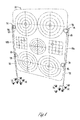
- FIG. 4 illustrates the target body being supported by a first and a second stand.
- FIG. 5 illustrates the target body being supported by the first and second stands, with the tabs on the second side of the target body being used to support a paper target.
- FIG. 6 illustrates a holder of one of the stands with the target body disposed within the holder.
- FIG. 7 illustrates a plurality of clay pigeons supported by the tabs on the second side of the target body.
- FIG. 8 illustrates a combination of clay pigeons and a paper target being supported by the tabs on the second side of the target body.
- FIG. 9 illustrates stands holding signage.
- FIG. 10 illustrates stands with a base portion for use on hard ground or frozen ground.
- FIG. 11 illustrates a store display or merchandiser.
- FIG. 12 is an end view of the merchandiser of FIG. 11 .
- FIG. 13 is a perspective view of the merchandiser of FIG. 11 and FIG. 12 .
- FIG. 1 illustrates a target body 10 having a plurality of target areas printed on a first side 12 of the target body 10 .
- the target areas may include bullseye targets 14 A, 14 B, 14 C, 14 D, 14 E as well as grid targets 16 A, 16 B.
- bullseye targets 14 A, 14 B, 14 C, 14 D, 14 E as well as grid targets 16 A, 16 B.
- other types of targets may be present such as pictorial representations of animals.
- the target body 10 is preferably formed of cardboard.
- FIG. 2 illustrates a second side 20 of the target body 10 where a plurality of clips or tabs 22 , 24 are present which may be used for holding clay targets or paper targets.
- each top tab 22 has a corresponding bottom tab 24 .
- One use for the tabs 22 , 24 is to hold clay targets.
- the bottom tab 24 when it folds back, creates a pocket for the clay target to drop into it so as to securely maintain the clay target in place.
- use of the target to hold clay targets is advantageous over ad hoc methods of placing clay targets
- the tabs 22 , 24 are to hold additional targets such as paper targets.
- the size, shape, and geometry 22 , 24 are well-suited for holding clay targets, although the present invention contemplates numerous variations in the particular structure, size, shape, and number of tabs or clips present.
- the target body 10 is made of cardboard or other material and the tabs 22 , 24 are integrally formed with the rest of the target body.
- the second side 20 may be die-cut hinged tab.
- pegboard hook loops 18 are at the top of the target body.
- the pegboard hook loops allow the target body to be suspended by hooks on a pegboard. This allows the target to be easily stored as well as displayed.
- FIG. 3 illustrates another embodiment of the second side of the target body where the clips or tabs are shown with alternative shape.
- each top tab 22 has corresponding bottom tabs 26 , 28 which are positioned at an angle and are also suitable for holding clay pigeons.
- the target is versatile and may be used for numerous purposes including as a plain target (with multiple target areas), as a clay pigeon holder, to hold paper targets as well as a backer for other targets.
- the target body is cardboard
- the target body may be formed by printing and then die cutting.
- the corrugation is in the vertical direction, but it need not be. This orientation creates stronger resistance and better paper memory to spring or hinge the tabs back.
- the cardboard may have a wall strength (as measured with an Edge Crust Test, “ECT”) of 44 and B flute corrugation.
- ECT Edge Crust Test
- Other types of cardboard may be using with other types of fluting for corrugation or other wall strengths.
- mullen board or fiber board may be used.
- FIG. 4 illustrates the target body being supported by a first and a second stand 40 A, 40 B.
- Each stand 40 A, 40 B may include an elongated body 50 with first and second opposite bottom and top ends 52 , 54 .
- the bottom end 52 serves as a stake.
- an additional structure 56 is provided for insertion into the ground.
- the additional structure 56 may be in the form of a right angle.
- holders 58 are positioned along the elongated body 50 .
- the holders 58 have an annular shape suitable for clipping the target body 10 in place.
- each holder 58 has a double loop structure 60 so that edges of the target may be positioned between the loops of the double loop structure 60 .
- the stand may be formed from a heavier steel upright rod assembly.
- a lighter weight curly Q steel wire may then be attached (such as through welding) to the rod to form the holder.
- Using the lighter weight curly Q allows for better flexibility and ease of inserting targets and signage into the curly Q.
- Attaching the lightweight curly Q (welded) to a heavier steel upright “rod” material allows for a much more rigid stand. This allows for a taller, stronger device. This design allows the user to attach a taller, heavier target or sign to the stand. This design with the heavier, stronger “rod” upright offers desirable wind resistance and rigidity.
- the lighter weight curly Q may flex apart to allow for insertion of a target or sign.
- FIG. 5 illustrates the target body being supported by the first and second stand 40 A, 40 B, with the clips or tabs on the second side of the target body being used to support a paper target 70 .
- FIG. 6 illustrates a holder 58 of a stand 40 with the target body disposed 10 within the holder 58 .
- the target body 10 may be positioned between a first loop 62 and a second loop 64 of the double loop structure 60 .
- FIG. 7 illustrates a plurality of clay targets 72 supported by the clips or tabs 22 , 24 on the second side of the target body 10 .
- FIG. 8 illustrates a combination of clay pigeons 72 and a paper target 70 being supported by the clips or tabs 22 , 24 on the second side of the target body 10 .
- FIG. 9 illustrates stands 40 A, 40 B holding signage 80 .
- the structure provided for the holders 58 may also be used to hold signage 80 .
- the stands 40 A, 40 B may be used to hold signage 80 .
- the stands 40 A, 40 B used for signage 80 may have the same structure as the holders used for targets.
- the stands 40 A, 40 B for signage 80 may have a larger diameter of wire so as to provide additional support as signage stands 40 A, 40 B may be used for longer periods of time than stands 40 A, 40 B used for targets.
- FIG. 10 illustrates an example of stands 40 A, 40 B with base members 84 .
- a base member 84 extends outwardly from each of the stands 40 A, 40 B.
- the base members 84 may be attached in various ways and may be removably attached.
- the base members 84 may have holders 86 in which one leg of the stand 40 A, 40 B may fit.
- the base members 84 allow the stands 40 A, 40 B to be used when the ground is hard, such as during winter time when the ground is frozen, on rock, cement or other hard surfaces.
- FIG. 11 , FIG. 12 and FIG. 13 illustrate a store display or merchandiser.
- the store display or merchandiser provides a means for displaying multi-purpose targets 10 and stands 40 A, 40 B in a manner that effectively illustrates the versatility and usefulness of the multi-purpose targets and holders.
- the store display is simple and effective at displaying a target in the stand.
- An arm on the store display may be used to hang the stands.
- the stands may be zip-tied together in sets of two.
- a first target may be mounted at a top portion of the support structure, and within a first and second of the plurality of stands. Additional targets and stands may be mounted below the first target.
Abstract
A multi-purpose reversible target includes a target body having a first side and a second side, a plurality of target areas printed on the first side of the target body, and a plurality of tabs integral with the target body and on the second side of the target body. A stand includes an elongated body having a top end and an opposite bottom end, the bottom end configured for insertion into ground and at least one holder comprising a first loop and a second operatively connected to the first loop to thereby allow for friction fit of an edge of signage between the first loop and the second loop.
Description
This application claims priority under 35 U.S.C. §119 to provisional application Ser. No. 61/384,595 filed Sep. 20, 2010, herein incorporated by reference in its entirety.
The present invention relates to shooting targets. More specifically, but not exclusively, the present invention relates to a multi-purpose reversible target and related stands and display.
Shooting is a popular and growing sport. Targets are used for various purposes including for practice, competition, and sighting weapons. One of the problems with targets is that they have limited life or function. What is needed is a versatile target with an extended life.
Another problem with use of targets relates to supporting the target itself. Ad hoc methods are often used to support targets during target practice. What is needed is a better way to support targets, especially one which would also be suitable for other purposes, such as supporting signage.
Therefore, it is a primary object, feature, or advantage of the present invention to improve over the state of the art.
It is a further object, feature, or advantage of the present invention to provide a multi-purpose and versatile target.
A further object, feature, or advantage of the present invention is to provide a means for supporting targets.
Yet another object, feature, or advantage of the present invention is to provide a means for holding clay targets.
A still further object, feature, or advantage of the present invention is to provide a single apparatus with multiple targets.
Yet another object, feature, or advantage of the present invention is to provide a display for use in marketing multi-purpose reversible targets and stands which is effective.
A still further object, feature, or advantage of the present invention is to provide stands suitable for holding targets or signs.
A still further object, feature, or advantage of the present invention is to provide a display suitable for use in a store to display targets and stands available for sale.
One or more of these and/or other objects, features, or advantages of the present invention will become apparent from the specification and claims that follow. No single embodiment need exhibit all of these objects, features, and advantages.
According to one aspect, a multi-purpose reversible target is provided. The target includes a target body having a first side and a second side. There are also target areas printed on the first side of the target body. Tabs integral with the target body are on the second side of the target body. The target body may be formed of cardboard. The target body may be supported by a first stand and a second stand, each of the stands having an elongated body with a top and a bottom and at least one holder between the top and the top and the bottom.
According to another aspect, a system of support for signage is provided. The system includes a first stand and a second stand. Each of the first stand and the second stand includes an elongated body having a top end and an opposite bottom end, the bottom end configured for insertion into ground. Each stand further includes at least one holder operatively connected to the elongated body and comprising a first loop and a second operatively connected to the first loop to thereby allow for friction fit of an edge of the signage between the first loop and the second loop. The bottom end of each stand may have both a first prong and a second prong for insertion into the ground. The first stand and the second stand may be formed from a wire or rod with lighter weight curly q wire being welded thereto.
The target body 10 shown in FIG. 1 is reversible. FIG. 2 illustrates a second side 20 of the target body 10 where a plurality of clips or tabs 22, 24 are present which may be used for holding clay targets or paper targets. As shown in FIG. 2 , each top tab 22 has a corresponding bottom tab 24. One use for the tabs 22, 24 is to hold clay targets. The bottom tab 24, when it folds back, creates a pocket for the clay target to drop into it so as to securely maintain the clay target in place. Thus, use of the target to hold clay targets is advantageous over ad hoc methods of placing clay targets
Another use for the tabs 22, 24 is to hold additional targets such as paper targets. The size, shape, and geometry 22, 24 are well-suited for holding clay targets, although the present invention contemplates numerous variations in the particular structure, size, shape, and number of tabs or clips present. Preferably the target body 10 is made of cardboard or other material and the tabs 22, 24 are integrally formed with the rest of the target body. For example the second side 20 may be die-cut hinged tab.
In addition, at the top of the target body are pegboard hook loops 18. The pegboard hook loops allow the target body to be suspended by hooks on a pegboard. This allows the target to be easily stored as well as displayed.
Thus, the target is versatile and may be used for numerous purposes including as a plain target (with multiple target areas), as a clay pigeon holder, to hold paper targets as well as a backer for other targets.
Where the target body is cardboard, the target body may be formed by printing and then die cutting. Preferably the corrugation is in the vertical direction, but it need not be. This orientation creates stronger resistance and better paper memory to spring or hinge the tabs back. Although various types of cardboard may be used, the cardboard may have a wall strength (as measured with an Edge Crust Test, “ECT”) of 44 and B flute corrugation. Other types of cardboard may be using with other types of fluting for corrugation or other wall strengths. Alternatively mullen board or fiber board may be used.
Various embodiments of a multi-purpose reversible target, stands for use with the reversible target or signage, and a store display for the multi-purpose reversible targets and stands have been disclosed. It is to be appreciated that although specific embodiments are described herein, the present invention contemplates numerous variations, modifications, options, and alternatives.
Claims (14)
1. A multi-purpose reversible target, comprising:
a planar target body having a first side and an opposite second side;
a plurality of target areas printed on the first side of the target body;
a plurality of tabs integral with the target body and extending outwardly from a planar surface of the second side of the target body, wherein the plurality of tabs are configured to support clay targets against the planar surface of the second side of the target body;
a first stand and a second stand supporting the planar target body;
wherein each of the first stand and the second stand comprises (a) an elongated body having a top end and an opposite bottom end, the bottom end configured for insertion into ground (b) at least one holder operatively connected to the elongated body and comprising a first straight portion connected to a first side of the elongated body, the first straight portion extending into a first loop, the first loop extending into a second loop, and a second straight portion extending from the second loop to an opposite second side of the elongated body to thereby allow for friction fit of an edge of the planar target body between the first loop and the second loop of the holder.
2. The multi-purpose reversible target of claim 1 wherein the planar target body and the tabs are formed of cardboard.
3. The multi-purpose reversible target of claim 2 wherein the cardboard is corrugated.
4. The multi-purpose reversible target of claim 1 wherein the plurality of target areas includes a plurality of bullseye targets.
5. The multi-purpose reversible target of claim 1 wherein the plurality of target areas includes a plurality of grid targets.
6. The multi-purpose reversible target of claim 1 further comprising a first base member operatively connected to the first stand and a second base member operatively connected to the second stand.
7. The multi-purpose reversible target of claim 1 wherein the plurality of tabs includes sets of tabs, the sets comprising a top tab and a corresponding bottom tab, wherein the bottom tab is configured to fold back to create a pocket for the clay target to drop into.
8. A multi-purpose reversible target, comprising:
a planar target body having a first side and an opposite second side;
a plurality of target areas printed on the first side of the planar target body;
a plurality of tabs integral with the planar target body and on the second side of the planar target body, the plurality of tabs configured to support clay targets;
a first stand and a second stand supporting the planar target body;
wherein each of the first stand and the second stand comprises (a) an elongated body having a top end and an opposite bottom end, the bottom end configured for insertion into ground (b) at least one holder operatively connected to the elongated body and comprising a first straight portion connected to a first side of the elongated body, the first straight portion extending into a first loop, the first loop extending into a second loop, and a second straight portion extending from the second loop to an opposite second side of the elongated body to thereby allow for friction fit of an edge of the planar target body between the first loop and the second loop of the holder.
9. The multi-purpose reversible target of claim 8 wherein the planar target body and the tabs are formed of cardboard.
10. The multi-purpose reversible target of claim 9 wherein the cardboard is corrugated.
11. The multi-purpose reversible target of claim 8 wherein the plurality of target areas includes a plurality of bullseye targets.
12. The multi-purpose reversible target of claim 8 , wherein the plurality of target areas includes a plurality of grid targets.
13. The multi-purpose reversible target of claim 8 further comprising a first base member operatively connected to the first stand and a second base member operatively connected to the second stand.
14. The multi-purpose reversible target of claim 8 wherein the plurality of tabs includes sets of tabs, the sets comprising a top tab and a corresponding bottom tab, wherein the bottom tab is configured to fold back to create a pocket for the clay target to drop into.
Priority Applications (2)
| Application Number | Priority Date | Filing Date | Title |
|---|---|---|---|
| US13/236,779 US8770587B2 (en) | 2010-09-20 | 2011-09-20 | Multi-purpose reversible target, stand, and display |
| US14/058,394 US8813401B2 (en) | 2010-09-20 | 2013-10-21 | Multi-purpose stand(s) |
Applications Claiming Priority (2)
| Application Number | Priority Date | Filing Date | Title |
|---|---|---|---|
| US38459510P | 2010-09-20 | 2010-09-20 | |
| US13/236,779 US8770587B2 (en) | 2010-09-20 | 2011-09-20 | Multi-purpose reversible target, stand, and display |
Related Child Applications (1)
| Application Number | Title | Priority Date | Filing Date |
|---|---|---|---|
| US14/058,394 Division US8813401B2 (en) | 2010-09-20 | 2013-10-21 | Multi-purpose stand(s) |
Publications (2)
| Publication Number | Publication Date |
|---|---|
| US20120068412A1 US20120068412A1 (en) | 2012-03-22 |
| US8770587B2 true US8770587B2 (en) | 2014-07-08 |
Family
ID=45817054
Family Applications (2)
| Application Number | Title | Priority Date | Filing Date |
|---|---|---|---|
| US13/236,779 Active 2032-05-31 US8770587B2 (en) | 2010-09-20 | 2011-09-20 | Multi-purpose reversible target, stand, and display |
| US14/058,394 Active US8813401B2 (en) | 2010-09-20 | 2013-10-21 | Multi-purpose stand(s) |
Family Applications After (1)
| Application Number | Title | Priority Date | Filing Date |
|---|---|---|---|
| US14/058,394 Active US8813401B2 (en) | 2010-09-20 | 2013-10-21 | Multi-purpose stand(s) |
Country Status (1)
| Country | Link |
|---|---|
| US (2) | US8770587B2 (en) |
Cited By (4)
| Publication number | Priority date | Publication date | Assignee | Title |
|---|---|---|---|---|
| US9689647B1 (en) | 2016-06-14 | 2017-06-27 | Todd Ian Dolgoff | Target stand |
| US10308393B2 (en) | 2016-03-16 | 2019-06-04 | Sony Corporation | Reconfigurable fixtures |
| US20230098427A1 (en) * | 2021-09-27 | 2023-03-30 | Ohio Guns, Ltd. | Shooting target stand |
| US11663932B2 (en) | 2020-10-28 | 2023-05-30 | MillerKnoll, Inc. | Stand for supporting a display board |
Families Citing this family (20)
| Publication number | Priority date | Publication date | Assignee | Title |
|---|---|---|---|---|
| US20120161396A1 (en) * | 2010-12-28 | 2012-06-28 | Munn Myron L | Target for patterning a shotgun |
| US8844934B2 (en) * | 2011-06-30 | 2014-09-30 | Jacob T. Dean | Hanging target frame |
| US8919778B2 (en) * | 2012-03-13 | 2014-12-30 | Daniel L. Fodera | Frangible target suspension apparatuses and methods of use thereof |
| US20150069706A1 (en) * | 2012-03-13 | 2015-03-12 | Daniel L. Fodera | Coupled frangible target suspension apparatuses and methods of use thereof |
| US9072953B2 (en) * | 2012-04-16 | 2015-07-07 | Darrell J Moore | Pitching device and method for baseball and softball sports |
| US20150047239A1 (en) * | 2013-08-15 | 2015-02-19 | Alan Ray Scott | Apparatus for social networking in outdoor environments |
| US9528798B1 (en) | 2014-02-26 | 2016-12-27 | James C. Hodge, Jr. | Portable and modular firearm target stand |
| USD742993S1 (en) | 2014-07-17 | 2015-11-10 | Birchwood Casey, LLC | Target holder |
| US9784538B2 (en) * | 2015-01-16 | 2017-10-10 | Action Target Inc. | High caliber target |
| US9927216B2 (en) | 2015-01-16 | 2018-03-27 | Action Target Inc. | Target system |
| US9784539B1 (en) | 2015-06-17 | 2017-10-10 | Patrick A. Preuss | Reactive target retention devices |
| US10215541B2 (en) * | 2016-01-12 | 2019-02-26 | Bret David Nicholson | Clay target shooting system |
| US10876821B2 (en) | 2017-01-13 | 2020-12-29 | Action Target Inc. | Software and sensor system for controlling range equipment |
| US11100821B1 (en) | 2017-02-17 | 2021-08-24 | Fourstar Group Inc. | Retractable banner |
| US10424230B1 (en) * | 2017-02-17 | 2019-09-24 | Fourstar Group Inc. | Retractable banner |
| US20180321018A1 (en) * | 2017-05-03 | 2018-11-08 | Wilson's Gun Shop, Inc | Firearm Training Target and a Method of Using the Same |
| US10049603B1 (en) * | 2017-10-17 | 2018-08-14 | Thomas Crouch | Protective guard for a sign |
| US10753054B2 (en) * | 2017-10-23 | 2020-08-25 | Theodore Eugene Davey | Anchor system for pole marker |
| US11029134B2 (en) | 2018-01-06 | 2021-06-08 | Action Target Inc. | Target carrier system having advanced functionality |
| US11561072B1 (en) * | 2021-03-24 | 2023-01-24 | Greg Larsen | Portable wind resistant target and sign stand |
Citations (18)
| Publication number | Priority date | Publication date | Assignee | Title |
|---|---|---|---|---|
| US2456302A (en) * | 1944-08-16 | 1948-12-14 | Ladimer M Mocnik | Supporting device |
| US2722420A (en) * | 1953-09-04 | 1955-11-01 | Thomas H Adamson | Multi-target holder |
| US2890051A (en) * | 1956-12-24 | 1959-06-09 | Melvin L Williams | Target holder |
| US3080166A (en) * | 1960-09-21 | 1963-03-05 | C F K Mfg Company | Adjustable target holder |
| US3613897A (en) * | 1970-01-05 | 1971-10-19 | I J Filler Enterprises Inc | Spring clip rack |
| US4323251A (en) * | 1980-02-13 | 1982-04-06 | Loveland William A | Target holder |
| US5211404A (en) * | 1992-02-07 | 1993-05-18 | Grant Robert P | Target mounting system |
| US5280920A (en) * | 1992-09-03 | 1994-01-25 | Knapper Ii William J | Portable target system |
| US5671924A (en) * | 1995-01-17 | 1997-09-30 | Scott; Van Edward | Portable target stand |
| US5678824A (en) * | 1996-08-05 | 1997-10-21 | Fortier; Kelly F. | Portable target stand |
| US5860654A (en) * | 1997-11-10 | 1999-01-19 | Jacobs; Bruce P. | Portable target assembly |
| US6435512B1 (en) * | 2000-04-19 | 2002-08-20 | James C. Beckwith, Sr. | Portable target stand and target |
| US6547204B1 (en) * | 2002-04-24 | 2003-04-15 | Robert Peck | Sign holding stake |
| US6755711B2 (en) * | 2001-05-31 | 2004-06-29 | Mcclung Karen Therese | Box games and activities |
| US20070158912A1 (en) * | 2006-01-10 | 2007-07-12 | Dmi Sports, Inc. | Dartboard cover |
| US7422217B2 (en) * | 2005-07-12 | 2008-09-09 | Hinnant Kenneth A | Target assembly for holding clay targets |
| US20090079136A1 (en) * | 2007-09-20 | 2009-03-26 | Matt Shalosky | Target stand system |
| US7845646B1 (en) * | 2006-10-25 | 2010-12-07 | Weber Thomas J | Practice targeting system and method of use thereof |
Family Cites Families (13)
| Publication number | Priority date | Publication date | Assignee | Title |
|---|---|---|---|---|
| US2333302A (en) * | 1941-05-16 | 1943-11-02 | Enk Grace | Garden marker |
| US3398475A (en) * | 1966-11-07 | 1968-08-27 | Donald M. Palmer | Tag holding device |
| US3494057A (en) * | 1967-07-24 | 1970-02-10 | Nuger Ford Products Co | Tire display card holder |
| US3474555A (en) * | 1967-08-07 | 1969-10-28 | Donald M Mccaffrey | Display card holder |
| US3540729A (en) * | 1968-12-12 | 1970-11-17 | Edward J Rahberger | Collapsible rack for holding targets,signals and the like |
| US3557474A (en) * | 1969-05-23 | 1971-01-26 | Donald M Palmer | Tag holding device |
| USD247265S (en) * | 1976-09-29 | 1978-02-14 | Ledebuhr Robert L | Sign stake |
| US4173086A (en) * | 1976-12-20 | 1979-11-06 | Hempfling Walter L | Sign structure |
| US4658527A (en) * | 1985-10-28 | 1987-04-21 | Pingel Matthias A | Sign holders |
| US5083390A (en) * | 1990-07-05 | 1992-01-28 | Edman David C | Modular sign |
| US5067683A (en) * | 1991-01-08 | 1991-11-26 | Quickfire, Inc. | Portable target holder |
| US5375801A (en) * | 1992-02-17 | 1994-12-27 | The South East Queensland Electricity Board | Temporary sign post |
| US6170183B1 (en) * | 1999-01-27 | 2001-01-09 | Patriot Signage Incorporated | Corrugated yard sign |
-
2011
- 2011-09-20 US US13/236,779 patent/US8770587B2/en active Active
-
2013
- 2013-10-21 US US14/058,394 patent/US8813401B2/en active Active
Patent Citations (18)
| Publication number | Priority date | Publication date | Assignee | Title |
|---|---|---|---|---|
| US2456302A (en) * | 1944-08-16 | 1948-12-14 | Ladimer M Mocnik | Supporting device |
| US2722420A (en) * | 1953-09-04 | 1955-11-01 | Thomas H Adamson | Multi-target holder |
| US2890051A (en) * | 1956-12-24 | 1959-06-09 | Melvin L Williams | Target holder |
| US3080166A (en) * | 1960-09-21 | 1963-03-05 | C F K Mfg Company | Adjustable target holder |
| US3613897A (en) * | 1970-01-05 | 1971-10-19 | I J Filler Enterprises Inc | Spring clip rack |
| US4323251A (en) * | 1980-02-13 | 1982-04-06 | Loveland William A | Target holder |
| US5211404A (en) * | 1992-02-07 | 1993-05-18 | Grant Robert P | Target mounting system |
| US5280920A (en) * | 1992-09-03 | 1994-01-25 | Knapper Ii William J | Portable target system |
| US5671924A (en) * | 1995-01-17 | 1997-09-30 | Scott; Van Edward | Portable target stand |
| US5678824A (en) * | 1996-08-05 | 1997-10-21 | Fortier; Kelly F. | Portable target stand |
| US5860654A (en) * | 1997-11-10 | 1999-01-19 | Jacobs; Bruce P. | Portable target assembly |
| US6435512B1 (en) * | 2000-04-19 | 2002-08-20 | James C. Beckwith, Sr. | Portable target stand and target |
| US6755711B2 (en) * | 2001-05-31 | 2004-06-29 | Mcclung Karen Therese | Box games and activities |
| US6547204B1 (en) * | 2002-04-24 | 2003-04-15 | Robert Peck | Sign holding stake |
| US7422217B2 (en) * | 2005-07-12 | 2008-09-09 | Hinnant Kenneth A | Target assembly for holding clay targets |
| US20070158912A1 (en) * | 2006-01-10 | 2007-07-12 | Dmi Sports, Inc. | Dartboard cover |
| US7845646B1 (en) * | 2006-10-25 | 2010-12-07 | Weber Thomas J | Practice targeting system and method of use thereof |
| US20090079136A1 (en) * | 2007-09-20 | 2009-03-26 | Matt Shalosky | Target stand system |
Cited By (4)
| Publication number | Priority date | Publication date | Assignee | Title |
|---|---|---|---|---|
| US10308393B2 (en) | 2016-03-16 | 2019-06-04 | Sony Corporation | Reconfigurable fixtures |
| US9689647B1 (en) | 2016-06-14 | 2017-06-27 | Todd Ian Dolgoff | Target stand |
| US11663932B2 (en) | 2020-10-28 | 2023-05-30 | MillerKnoll, Inc. | Stand for supporting a display board |
| US20230098427A1 (en) * | 2021-09-27 | 2023-03-30 | Ohio Guns, Ltd. | Shooting target stand |
Also Published As
| Publication number | Publication date |
|---|---|
| US20140041267A1 (en) | 2014-02-13 |
| US20120068412A1 (en) | 2012-03-22 |
| US8813401B2 (en) | 2014-08-26 |
Similar Documents
| Publication | Publication Date | Title |
|---|---|---|
| US8770587B2 (en) | Multi-purpose reversible target, stand, and display | |
| CA2242045C (en) | Reinforced strip display assembly capable of supporting high volumes of smaller impulse merchandise | |
| US4658527A (en) | Sign holders | |
| US20230351926A1 (en) | Signage Systems And Merchandising Display Assemblies | |
| US7950536B2 (en) | System for displaying merchandise in front of backer material | |
| US5566837A (en) | Ball cap storage and display rack | |
| US20150068990A1 (en) | Signage systems and merchandising display assemblies | |
| US11263934B2 (en) | Portable reconfigurable display system | |
| US6457684B1 (en) | Support system for banners | |
| US20160203740A1 (en) | Signage systems | |
| US7395937B2 (en) | Adjustable bulletin board | |
| CA2828849C (en) | Display fixture having a display hook | |
| US7788836B2 (en) | Device and method for hanging photographs or cards | |
| US6920985B2 (en) | Display system for wrapping paper and adhesive tape | |
| US11549786B2 (en) | Multi-sided target assembly | |
| US9528798B1 (en) | Portable and modular firearm target stand | |
| US8448362B2 (en) | Curved display arrangement | |
| JP3113539U (en) | Display tools | |
| US20070145208A1 (en) | Apparatus for visual display of greeting cards | |
| JP2012170537A (en) | Easel | |
| JP3110138U (en) | Start display such as ground golf | |
| JP4717150B1 (en) | Fastener | |
| CN204378508U (en) | The fixture of ground, a kind of field chart rack | |
| JPH0130939Y2 (en) | ||
| JP3115754U (en) | Assembled paper advertising billboard for special events |
Legal Events
| Date | Code | Title | Description |
|---|---|---|---|
| STCF | Information on status: patent grant |
Free format text: PATENTED CASE |
|
| MAFP | Maintenance fee payment |
Free format text: PAYMENT OF MAINTENANCE FEE, 4TH YR, SMALL ENTITY (ORIGINAL EVENT CODE: M2551) Year of fee payment: 4 |
|
| MAFP | Maintenance fee payment |
Free format text: PAYMENT OF MAINTENANCE FEE, 8TH YR, SMALL ENTITY (ORIGINAL EVENT CODE: M2552); ENTITY STATUS OF PATENT OWNER: SMALL ENTITY Year of fee payment: 8 |