US8770041B2 - Rotational measurement system for fluid meters - Google Patents
Rotational measurement system for fluid meters Download PDFInfo
- Publication number
- US8770041B2 US8770041B2 US13/497,489 US201013497489A US8770041B2 US 8770041 B2 US8770041 B2 US 8770041B2 US 201013497489 A US201013497489 A US 201013497489A US 8770041 B2 US8770041 B2 US 8770041B2
- Authority
- US
- United States
- Prior art keywords
- magnet
- fluid
- rotor
- meter
- cavity
- Prior art date
- Legal status (The legal status is an assumption and is not a legal conclusion. Google has not performed a legal analysis and makes no representation as to the accuracy of the status listed.)
- Active, expires
Links
- 239000012530 fluid Substances 0.000 title claims abstract description 80
- 238000005259 measurement Methods 0.000 title claims description 21
- 230000000712 assembly Effects 0.000 claims description 5
- 238000000429 assembly Methods 0.000 claims description 5
- 238000004880 explosion Methods 0.000 claims description 3
- 238000006073 displacement reaction Methods 0.000 description 6
- 238000013461 design Methods 0.000 description 5
- 239000000523 sample Substances 0.000 description 4
- 239000000919 ceramic Substances 0.000 description 3
- 230000008878 coupling Effects 0.000 description 3
- 238000010168 coupling process Methods 0.000 description 3
- 238000005859 coupling reaction Methods 0.000 description 3
- 238000004519 manufacturing process Methods 0.000 description 3
- 239000000463 material Substances 0.000 description 3
- 230000009347 mechanical transmission Effects 0.000 description 3
- 238000000034 method Methods 0.000 description 3
- 239000012855 volatile organic compound Substances 0.000 description 3
- 238000005299 abrasion Methods 0.000 description 2
- 210000004907 gland Anatomy 0.000 description 2
- 239000007788 liquid Substances 0.000 description 2
- 238000012856 packing Methods 0.000 description 2
- 229910001220 stainless steel Inorganic materials 0.000 description 2
- 239000010935 stainless steel Substances 0.000 description 2
- CWYNVVGOOAEACU-UHFFFAOYSA-N Fe2+ Chemical compound [Fe+2] CWYNVVGOOAEACU-UHFFFAOYSA-N 0.000 description 1
- 238000013459 approach Methods 0.000 description 1
- 230000009286 beneficial effect Effects 0.000 description 1
- 238000009529 body temperature measurement Methods 0.000 description 1
- 230000009977 dual effect Effects 0.000 description 1
- 238000005516 engineering process Methods 0.000 description 1
- 238000009434 installation Methods 0.000 description 1
- 238000012423 maintenance Methods 0.000 description 1
- 230000003287 optical effect Effects 0.000 description 1
- 230000035515 penetration Effects 0.000 description 1
- 238000012546 transfer Methods 0.000 description 1
Images


Classifications
-
- G—PHYSICS
- G01—MEASURING; TESTING
- G01F—MEASURING VOLUME, VOLUME FLOW, MASS FLOW OR LIQUID LEVEL; METERING BY VOLUME
- G01F1/00—Measuring the volume flow or mass flow of fluid or fluent solid material wherein the fluid passes through a meter in a continuous flow
- G01F1/05—Measuring the volume flow or mass flow of fluid or fluent solid material wherein the fluid passes through a meter in a continuous flow by using mechanical effects
- G01F1/06—Measuring the volume flow or mass flow of fluid or fluent solid material wherein the fluid passes through a meter in a continuous flow by using mechanical effects using rotating vanes with tangential admission
- G01F1/075—Measuring the volume flow or mass flow of fluid or fluent solid material wherein the fluid passes through a meter in a continuous flow by using mechanical effects using rotating vanes with tangential admission with magnetic or electromagnetic coupling to the indicating device
Definitions
- the present invention relates to fluid flow meters. More particularly, the present invention relates to a fluid flow meter which includes a rotor that is magnetically rather than mechanically linked to a rotational measuring device in order to eliminate potential leak paths between the flow path and the surrounding environment.
- fluid meters are used to accurately measure large amounts of fluid passing through a pipeline in order to facilitate selling or otherwise transferring custody of the fluid.
- One type of fluid meter commonly used for this purpose is a reciprocating blade positive displacement (PD) meter.
- PD reciprocating blade positive displacement
- FIG. 1 such meters commonly include a meter housing, a fluid inlet and a fluid outlet.
- a slotted cylindrical rotor is rotatably mounted in the housing.
- a cam is fixedly mounted to the housing within the rotor.
- a number of blades are slidably mounted in the rotor slots and are fitted with cam following bearings.
- As fluid is pumped through the meter it impinges on the blades, forcing the rotor to rotate within the housing.
- the cam causes the blades to reciprocate in and out of the rotor.
- the blades on opposite sides of the cam may be fixed to each other, such that they reciprocate as a unit.
- a maximum of two of the blades are fully extended at any given time.
- the space between the housing, the rotor and the two extended blades is the measuring chamber.
- the space between the housing, the rotor and the inlet and outlet is filled with a block of material which prevents direct fluid flow from the inlet to the outlet, thus forcing all the fluid through the measuring chamber.
- the cam causes the blades to retract into the rotor as they approach and pass the block.
- the volume of the measuring chamber is accurately known, a known volume of liquid passes through the meter for every 1 ⁇ 4 revolution of the rotor.
- the total quantity of liquid passing through the meter can be calculated by accurately measuring the number of revolutions of the rotor.
- the housing may be double walled, with the space between the walls allowed to fill with the process fluid. This arrangement insures that the inner wall is pressure balanced and is not distorted by the pressure. Such distortion can change the volume of the measurement chamber and thus degrade the accuracy of the meter.
- an exemplary prior art reciprocating blade PD meter is shown to include a housing 10 and a cover 12 which is bolted to the housing.
- a mechanical counter 20 is mounted above the cover.
- a rotor 14 is rotatably mounted on a central shaft 16 inside the housing.
- a first set of gears 22 transmits the rotation of the rotor 14 to a secondary shaft 24 .
- the secondary shaft passes through the cover 12 , and packing gland 26 is provided between the cover and the secondary shaft.
- a second set of gears 28 transmits the rotation of the secondary shaft 24 to the mechanical counter 20 .
- the mechanical counter may include an optical encoder.
- a fluid meter having a housing which comprises a cavity that defines a flow bore through which a fluid to be metered is directed; a rotor which is rotatably supported in the cavity and is set into rotation by the fluid flowing through the flow bore; a first magnet which is connected to the rotor; a second magnet which is magnetically coupled to the first magnet; a cap member which is positioned over the first magnet and separates the second magnet from the cavity; and a rotary encoder which is operatively coupled to the second magnet.
- rotation of the rotor is magnetically transmitted through the cap member from the first magnet to the second magnet and is detected by the rotary encoder.
- the rotary encoder comprises a magnetic rotary encoder.
- the rotary encoder may comprise an integrated circuit magnetic rotary encoder.
- the fluid meter also includes a cover which is secured to the housing over the cavity and which comprises a chamber within which the second magnet and the rotary encoder are positioned.
- the chamber may be closed by an explosion proof cap.
- the rotor comprises an axially extending annular end portion which is rotatably supported in a bearing that is mounted to the cover.
- the first magnet may be connected to the end portion.
- the cover comprises an opening which is connected to the chamber and the cap member is secured to the cover over the opening.
- the cap member may comprise a generally tubular configuration and the first magnet may extend through the opening and into the cap member.
- the second magnet may comprise a generally cylindrical base portion which is positioned coaxially over the cap member and a shaft which extends axially from the base portion towards the rotary encoder.
- the shaft may be rotatably supported in a bearing which is mounted to a support member that is secured to the cover over the cap member.
- the rotary encoder may comprise an integrated circuit magnetic rotary encoder which magnetically detects the rotation of the distal end of the shaft or of a third magnet which is disposed on the distal end of the shaft.
- the rotor may comprise a number of blade assemblies, each of which includes two interconnected, diametrically opposite blades.
- each blade may be laterally restrained between a first inside surface portion of the housing and a second inside surface portion of the cover and between a first retaining ring which is mounted in the housing radially inwardly of the first inside surface portion and a second retaining ring which is mounted in the cover radially inwardly of the second inside surface portion.
- plastic wear strips may be mounted to the lateral ends of each of the blades.
- the fluid meter also includes a measurement element which is mounted in the cavity on one side of the rotor and a block which is mounted in the cavity on the diametrically opposite side of the rotor.
- the measurement element may be adjustably connected to the housing.
- the block element may be adjustably connected to the housing.
- the fluid meter of the present invention provides many advantages over the prior art. Since the rotor is magnetically rather than mechanically coupled to the rotary encoder, the pressurized cavity does not need to be penetrated by mechanical transmission elements, thereby eliminating the possibility of fluid leaking out of the meter and into the surrounding environment. In addition, since the rotor blades are laterally restrained, the fluid meter can operate in multiple orientations without affecting the meter factor output of the meter. Furthermore, since the measurement element and the block are adjustably connected to the housing, the meter tolerances can be adjusted during assembly, thereby eliminating the need to maintain relatively restrictive manufacturing tolerances.
- FIG. 1 is a schematic illustration of a prior art reciprocating blade positive displacement meter
- FIG. 2 is a top plan, partial cross sectional view of a prior art reciprocating blade positive displacement meter
- FIG. 3 is an enlarged cross sectional view of the portion of the prior art meter designated “A” in FIG. 2 ;
- FIG. 4 is a side elevation, partial cross sectional view of an exemplary embodiment of the fluid meter of the present invention.
- FIG. 5 is a cross sectional view of the fluid meter taken along line 5 - 5 of FIG. 4 ;
- FIG. 6 is a side elevation view of the fluid meter of FIG. 4 ;
- FIG. 7 is an enlarged cross sectional view of the portion of the fluid meter designated “B” in FIG. 4 showing an embodiment of the rotational measurement system of the meter;
- FIG. 8 is an enlarged cross sectional view of the rotational measurement system shown in FIG. 7 ;
- FIG. 9 is an enlarged cross sectional view of a portion of the fluid meter of FIG. 4 showing an embodiment of the bearing support system for the rotor assembly component of the meter;
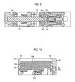
- FIG. 10 is an enlarged cross sectional view of the portion of the fluid meter designated “C” in FIG. 4 showing an embodiment of the blade component of the meter.
- FIGS. 4 through 6 A reciprocating blade positive displacement meter in accordance with an exemplary embodiment of the present invention is shown in FIGS. 4 through 6 .
- the meter includes a housing which comprises an internal cavity 41 over which a cover 42 is bolted.
- the cavity 41 defines a flow bore 45 through which a fluid to be metered is directed.
- the fluid enters the flow bore 45 through an inlet 47 a and exits the flow bore through an outlet 47 b.
- the meter also includes a shaft 44 which is positioned transversely across the cavity 41 and is secured to the inside of the housing 40 .
- a slotted, generally cylindrical rotor assembly 48 is rotatably mounted to the shaft via bearings 82 and 84 .
- the rotor 48 comprises an axially extending annular end portion 49 which is rotatably supported in a bearing 86 that is mounted in the cover 42 .
- the bearings 82 , 84 and 86 may be made of any suitable material, such as a ceramic, a ceramic hybrid or stainless steel.
- the rotor 48 includes two blade assemblies 51 .
- Each blade assembly 51 comprises two interconnected, diametrically opposite blades 50 a and 50 b , each of which is configured to slide within a corresponding slot in the rotor 48 .
- Each blade assembly 51 also includes two cam follower bearings 52 a and 52 b .
- a cam 46 which is fixedly mounted on the shaft 44 engages the cam follower bearings 52 a , 52 b and forces the blade assemblies 51 to reciprocate in the rotor slots.
- each of the blades 50 a , 50 b is laterally restrained between a first inside surface portion 53 of the housing 40 and a second inside surface portion 55 of the cover 42 and between a first retaining ring 54 which is mounted in the housing radially inwardly of the first inside surface portion and a second retaining ring 56 which is mounted in the cover radially inwardly of the second inside surface portion.
- This arrangement prevents the blades 50 a , 50 b from cocking when the meter mounting orientation is changed. As a result, the meter factor is not affected by the orientation of the meter.
- plastic wear strips 58 a and 58 b may be attached to the lateral ends of each of the blades 50 a , 50 b to protect the blades against abrasion.
- the meter also includes a measurement element 72 which is mounted against the inside wall of the housing 40 .
- the space between the measurement element 72 and the rotor 48 defines the measuring chamber of the meter.
- the position of the measuring element 72 may be adjusted via an adjustment screw 78 which is accessed via a plug 80 .
- the meter also includes a block 70 which is mounted against the inside wall of the housing 40 opposite the measurement element 72 .
- the position of the block 70 may be adjusted via an adjustment screw 74 which is accessed via plug 76 .
- the cover 42 may be provided with two temperature probe bosses 120 in which temperature sensing elements, such as resistant temperature devices (RTD's), may be installed.
- temperature sensing elements such as resistant temperature devices (RTD's)
- One temperature probe boss 120 may be used by the customer to monitor the temperature of the metered fluid, thereby eliminating the need to install a separate temperature sensing device in the pipeline to which the meter is connected.
- the other probe boss 120 may be used by Weights and Measures authorities to validate the first temperature measurement device.
- the cover 42 may also be provided with drain plugs 130 to allow the fluid to be drained from the meter in either a horizontal or vertical orientation, thereby providing ease of installation for the user.
- the rotation measurement system generally 90 , includes a generally cylindrical first magnet 92 which is connected to the end portion 49 of the rotor 48 .
- the first magnet 92 extends through an opening 91 in the cover 42 which is connected to the chamber 43 .
- a generally tubular cap member 96 is positioned over the first magnet 92 and is secured and sealed to the cover 42 over the opening 91 .
- the cap member 96 which is preferably made of a non-ferrous material, is a pressure containing member which prevents fluid in the cavity 41 from entering the chamber 43 .
- the first magnet 92 is magnetically coupled to a second magnet 94 which is positioned on the opposite side of the cap member 96 .
- the second magnet includes a generally cylindrical base portion 95 which is positioned concentrically over the first magnet 92 and a shaft 97 which extends axially from the base portion.
- the shaft 97 is rotatably supported in a bearing 88 which is mounted to a support member 98 that is secured to the cover 42 over the cap member 96 .
- Rotation of the second magnet 94 , and thus the rotor 48 is detected by a suitable encoder, such as an integrated circuit magnetic rotary encoder 102 .
- the rotary encoder 102 detects the incremental angular turns of the distal end of the axial extension 97 or, more preferably, a third magnet 100 which is disposed on the distal end of the axial extension.
- the rotary encoder 102 which may be either programmable or non-programmable, outputs a specified number of electronic pulses per rotation of the axial extension 97 or the third magnet 100 . These pulses are then be processed by a microprocessor to calculate fluid flow through the meter.
- the rotary encoder 102 may also be programmed to generate output pulses which are based on the absolute angular position of the axial extension 97 or the third magnet 100 .
- the microprocessor could be programmed to provide linearization of the meter rotational performance to extend the usable flow rate range of the meter from, e.g., 10:1 to 50:1, consistent with global legal metrology Weights and Measurement requirements.
- the meter of the present invention provides many advantages over prior art meters.
- the meter includes an integrated electronics housing (i.e., the chamber 43 ) which reduces the overall size and weight of the meter and eliminates the cost of separate housings. This is especially beneficial for meters which are mounted on delivery tanker vehicles.
- the meter also has an integral explosion-proof cover design that encloses the electronics and any other physical sensing elements that may be desired, such as temperature probes and pressure sensors.
- the meter of the present invention employs a captive blade design that allows the meter to operate in multiple physical mounting positions without affecting the meter factor output.
- the physical mount does not degrade meter performance.
- the captive blades allow for high measurement accuracy even when the meter is mounted on a delivery tanker truck and the truck is parked on an incline.
- the captive blade design also allows customers to mount the meter in the orientation that best fits their applications.
- plastic wear strips on the blade end surfaces provide an abrasion resistant surface. The captive blades and plastic wear strips allow the meter to be operated with the live shaft in a horizontal or off-plane (angled from the horizontal plane) orientation without affecting either the metrological accuracy or the repeatability of the meter.
- the meter of the present invention comprises adjustable measuring elements (i.e., the block 70 and the measurement element 72 ) which allow adjustment of the meter tolerances during assembly in order to accommodate less restrictive manufacturing tolerances than are typically employed on positive displacement meters.
- the adjustable measuring elements also simplify meter assembly and maintenance.
- the meter of the present invention may be produced in a cost effective manner and yet maintain the accuracy required for fluid custody transfer.
- Microprocessor technology combined with the unique use of an angular position sensing integrated circuit allows the effective range of the meter to be extended from that typically provided by mechanical measuring devices.
- the meter measurement chamber is designed to support use of the meter in high pressure applications that previously could normally not be achieved with prior art single housing meters, thus eliminating the need for a dual housing design to keep the measuring element pressure stabilized.
- the meter of the present invention uses a magnetic coupling to transmit rotation of the rotor to a measurement system located outside of the meter housing. This eliminates the need to penetrate the pressure containing parts of the meter in order to transmit rotor rotation, thus eliminating the risk that volatile organic compounds will escape into the atmosphere through, e.g., a packing gland.
- the magnetic coupling also eliminates the gear train that prior art meters commonly use to transmit rotor rotation, thus reducing the part count and cost of the meter.
- the three-bearing ceramic hybrid and/or stainless steel bearing shaft support system allows for free rotation of the rotor 48 over an extended performance turndown ration of 50:1 or greater, thus allowing for repeatable performance across a wide metrological measurement range.
Abstract
Description
Claims (23)
Priority Applications (1)
| Application Number | Priority Date | Filing Date | Title |
|---|---|---|---|
| US13/497,489 US8770041B2 (en) | 2009-09-22 | 2010-09-22 | Rotational measurement system for fluid meters |
Applications Claiming Priority (3)
| Application Number | Priority Date | Filing Date | Title |
|---|---|---|---|
| US27722609P | 2009-09-22 | 2009-09-22 | |
| PCT/US2010/002596 WO2011037625A1 (en) | 2009-09-22 | 2010-09-22 | Improved rotational measurement system for fluid meters |
| US13/497,489 US8770041B2 (en) | 2009-09-22 | 2010-09-22 | Rotational measurement system for fluid meters |
Publications (2)
| Publication Number | Publication Date |
|---|---|
| US20120240689A1 US20120240689A1 (en) | 2012-09-27 |
| US8770041B2 true US8770041B2 (en) | 2014-07-08 |
Family
ID=43796134
Family Applications (1)
| Application Number | Title | Priority Date | Filing Date |
|---|---|---|---|
| US13/497,489 Active 2031-04-18 US8770041B2 (en) | 2009-09-22 | 2010-09-22 | Rotational measurement system for fluid meters |
Country Status (2)
| Country | Link |
|---|---|
| US (1) | US8770041B2 (en) |
| WO (1) | WO2011037625A1 (en) |
Families Citing this family (3)
| Publication number | Priority date | Publication date | Assignee | Title |
|---|---|---|---|---|
| DE112013001969T5 (en) * | 2012-08-02 | 2015-01-08 | Fuji Electric Co., Ltd. | Metal support plate |
| US20150260562A1 (en) * | 2014-03-14 | 2015-09-17 | Andrew Dawn | Wireless liquid metering device |
| WO2017184824A1 (en) * | 2016-04-20 | 2017-10-26 | Dignity Health | Systems and methods for a cerebrospinal fluid flow detector |
Citations (10)
| Publication number | Priority date | Publication date | Assignee | Title |
|---|---|---|---|---|
| US3721483A (en) | 1972-02-15 | 1973-03-20 | Singer Co | Adjustable diameter roller bearing |
| US3949606A (en) | 1973-09-10 | 1976-04-13 | Blancett Joe H | Fluid meter and adapter units therefor |
| US4275291A (en) | 1978-08-21 | 1981-06-23 | Wilgood Corporation | Rotation sensor |
| US4377091A (en) | 1981-03-02 | 1983-03-22 | The Foxboro Company | Vertical axis turbine flowmeter |
| US4553433A (en) | 1983-05-13 | 1985-11-19 | The Singer Company | Rotary meter with integral instrument housing |
| US5271526A (en) | 1990-12-07 | 1993-12-21 | Titan Industries, Inc. | Programmable additive controller |
| US6894484B2 (en) * | 2001-01-25 | 2005-05-17 | Nsk Ltd. | Wheel rotation detecting device |
| US6945125B2 (en) | 2003-12-03 | 2005-09-20 | Daniel Industries, Inc. | High resolution pulse count interface |
| US7281899B1 (en) | 1997-05-05 | 2007-10-16 | King Of Frans, Inc. | Quick assembly blades for ceiling fans |
| US7557569B2 (en) * | 2006-02-28 | 2009-07-07 | Nsk Ltd. | State measuring apparatus for rotary machine |
-
2010
- 2010-09-22 US US13/497,489 patent/US8770041B2/en active Active
- 2010-09-22 WO PCT/US2010/002596 patent/WO2011037625A1/en active Application Filing
Patent Citations (10)
| Publication number | Priority date | Publication date | Assignee | Title |
|---|---|---|---|---|
| US3721483A (en) | 1972-02-15 | 1973-03-20 | Singer Co | Adjustable diameter roller bearing |
| US3949606A (en) | 1973-09-10 | 1976-04-13 | Blancett Joe H | Fluid meter and adapter units therefor |
| US4275291A (en) | 1978-08-21 | 1981-06-23 | Wilgood Corporation | Rotation sensor |
| US4377091A (en) | 1981-03-02 | 1983-03-22 | The Foxboro Company | Vertical axis turbine flowmeter |
| US4553433A (en) | 1983-05-13 | 1985-11-19 | The Singer Company | Rotary meter with integral instrument housing |
| US5271526A (en) | 1990-12-07 | 1993-12-21 | Titan Industries, Inc. | Programmable additive controller |
| US7281899B1 (en) | 1997-05-05 | 2007-10-16 | King Of Frans, Inc. | Quick assembly blades for ceiling fans |
| US6894484B2 (en) * | 2001-01-25 | 2005-05-17 | Nsk Ltd. | Wheel rotation detecting device |
| US6945125B2 (en) | 2003-12-03 | 2005-09-20 | Daniel Industries, Inc. | High resolution pulse count interface |
| US7557569B2 (en) * | 2006-02-28 | 2009-07-07 | Nsk Ltd. | State measuring apparatus for rotary machine |
Also Published As
| Publication number | Publication date |
|---|---|
| US20120240689A1 (en) | 2012-09-27 |
| WO2011037625A1 (en) | 2011-03-31 |
Similar Documents
| Publication | Publication Date | Title |
|---|---|---|
| US6694825B2 (en) | Method and apparatus for flow control of NH3 | |
| US8770041B2 (en) | Rotational measurement system for fluid meters | |
| US7942070B2 (en) | Flow rate sensor | |
| EP1889014A1 (en) | Oval gear meter | |
| MX2008011317A (en) | Apparatus for measuring and/or controlling liquid levels. | |
| CA2764083C (en) | Mass flow meter | |
| JPS589025A (en) | Flowmeter | |
| JP6436642B2 (en) | Membrane gas meter and manufacturing method thereof | |
| FI87607C (en) | Method and apparatus for measuring the volume of a flowing liquid | |
| US9322682B2 (en) | Insertable flow meter | |
| JPS6335924B2 (en) | ||
| WO2012138239A1 (en) | Velocity type flow meter with electronic readout | |
| US4091653A (en) | Turbine meter in-line checking apparatus and method | |
| KR101810976B1 (en) | Gas-meter having fuction of compensating temperature and pressure | |
| CN103674124A (en) | Gear type flow direction flow transmitter | |
| US7168328B2 (en) | Measuring device for determining the mass rate of flow of a mass flow | |
| KR101488277B1 (en) | Volume type flow meter | |
| FI78781B (en) | MAETANORDNING FOER MAETNING AV STROEMNING OCH / ELLER DESS EGENSKAPER. | |
| RU2337319C1 (en) | Tangential turbine flow meter | |
| US4157662A (en) | Liquid meter with compensated dual outputs | |
| US11448540B2 (en) | High resolution elliptical gear flowmeter | |
| RU2234686C2 (en) | Liquid gauging tank | |
| KR102120471B1 (en) | Blocking rotor type flow meter | |
| FI70324C (en) | FOERBAETTRINGAR VID WOLTMANN-MAETARE | |
| Siev et al. | Positive Displacement Liquid Meters and Provers |
Legal Events
| Date | Code | Title | Description |
|---|---|---|---|
| AS | Assignment |
Owner name: FMC TECHNOLOGIES, INC., TEXAS Free format text: ASSIGNMENT OF ASSIGNORS INTEREST;ASSIGNORS:SMITH, ROBERT M.;LANTZ, JEFFREY W.;BRETER, JAMES C.;REEL/FRAME:028287/0629 Effective date: 20120419 |
|
| STCF | Information on status: patent grant |
Free format text: PATENTED CASE |
|
| MAFP | Maintenance fee payment |
Free format text: PAYMENT OF MAINTENANCE FEE, 4TH YEAR, LARGE ENTITY (ORIGINAL EVENT CODE: M1551) Year of fee payment: 4 |
|
| MAFP | Maintenance fee payment |
Free format text: PAYMENT OF MAINTENANCE FEE, 8TH YEAR, LARGE ENTITY (ORIGINAL EVENT CODE: M1552); ENTITY STATUS OF PATENT OWNER: LARGE ENTITY Year of fee payment: 8 |
|
| AS | Assignment |
Owner name: JPMORGAN CHASE BANK, N.A., AS ADMINISTRATIVE AGENT, TEXAS Free format text: SECURITY INTEREST;ASSIGNORS:FMC TECHNOLOGIES, INC.;SCHILLING ROBOTICS, LLC;REEL/FRAME:064193/0870 Effective date: 20230623 Owner name: DNB BANK ASA, NEW YORK BRANCH, AS ADMINISTRATIVE AGENT, NEW YORK Free format text: SECURITY INTEREST;ASSIGNORS:FMC TECHNOLOGIES, INC.;SCHILLING ROBOTICS, LLC;REEL/FRAME:064193/0810 Effective date: 20230623 |
|
| AS | Assignment |
Owner name: FMC TECHNOLOGIES, INC., TEXAS Free format text: RELEASE BY SECURED PARTY;ASSIGNOR:DNB BANK ASA, NEW YORK BRANCH, AS ADMINISTRATIVE AGENT;REEL/FRAME:066733/0052 Effective date: 20240311 Owner name: FMC TECHNOLOGIES, INC., TEXAS Free format text: RELEASE BY SECURED PARTY;ASSIGNOR:JPMORGAN CHASE BANK, N.A., AS ADMINISTRATIVE AGENT;REEL/FRAME:066732/0976 Effective date: 20240311 |