US8769758B2 - Force sensing oral care instrument - Google Patents
Force sensing oral care instrument Download PDFInfo
- Publication number
- US8769758B2 US8769758B2 US13/237,443 US201113237443A US8769758B2 US 8769758 B2 US8769758 B2 US 8769758B2 US 201113237443 A US201113237443 A US 201113237443A US 8769758 B2 US8769758 B2 US 8769758B2
- Authority
- US
- United States
- Prior art keywords
- load member
- handle
- force
- less
- oral hygiene
- Prior art date
- Legal status (The legal status is an assumption and is not a legal conclusion. Google has not performed a legal analysis and makes no representation as to the accuracy of the status listed.)
- Active, expires
Links
Images


Classifications
-
- A—HUMAN NECESSITIES
- A46—BRUSHWARE
- A46B—BRUSHES
- A46B15/00—Other brushes; Brushes with additional arrangements
- A46B15/0002—Arrangements for enhancing monitoring or controlling the brushing process
- A46B15/0004—Arrangements for enhancing monitoring or controlling the brushing process with a controlling means
- A46B15/0012—Arrangements for enhancing monitoring or controlling the brushing process with a controlling means with a pressure controlling device
-
- A—HUMAN NECESSITIES
- A46—BRUSHWARE
- A46B—BRUSHES
- A46B15/00—Other brushes; Brushes with additional arrangements
- A46B15/0002—Arrangements for enhancing monitoring or controlling the brushing process
- A46B15/0038—Arrangements for enhancing monitoring or controlling the brushing process with signalling means
- A46B15/0044—Arrangements for enhancing monitoring or controlling the brushing process with signalling means with light signalling means
-
- A—HUMAN NECESSITIES
- A46—BRUSHWARE
- A46B—BRUSHES
- A46B2200/00—Brushes characterized by their functions, uses or applications
- A46B2200/10—For human or animal care
- A46B2200/1066—Toothbrush for cleaning the teeth or dentures
Definitions
- the present invention pertains to a personal hygiene device, more particularly to a personal hygiene device including a force indication system.
- dental professionals may recommend the use of a soft bristled toothbrush.
- the use of a soft bristled toothbrush does not preclude the application of high brushing forces to the oral cavity.
- studies have shown that the cleaning ability of a toothbrush may in fact be reduced if brushing force is increased to too high a level.
- the insert comprises a load member capable of pivoting with respect to the housing; an output source disposed in electromagnetic communication with the load member, the output source having a first contact arm and a second contact arm; a power source in electrical communication with the output source, the power source having a first contact area and a second contact area; an engagement section capable of receiving an oral care attachment; and an indication element forming an outer facing surface of the oral hygiene implement.
- the first contact arm makes contact with a first contact area and/or the second contact arm makes contact with the second contact area thereby causing the power source to deliver power to the output source, wherein the output source provides electromagnetic energy to the load member, wherein the load member transmits the electromagnetic energy from the output source to the indication element, and wherein load member, the indication element, and the engagement section are integral with one another.
- FIG. 1 is an elevational view showing a left side of an oral hygiene implement, e.g. a toothbrush, constructed in accordance with the present invention.
- an oral hygiene implement e.g. a toothbrush
- FIG. 2A is a plan view showing an insert of the toothbrush for FIG. 1 .
- FIG. 2B is a plan view of the insert of FIG. 1 with an optional removable head/neck.
- FIG. 3A is a close up view showing a proximal portion of the insert of FIG. 2B .
- FIG. 3B is a close up view showing the proximal portion of the insert of FIG. 2B with a load member removed for ease of explanation.
- FIG. 3C is a close up view showing the proximal portion of the insert of FIG. 2B with support removed for ease of explanation.
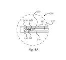
- FIG. 4A is a close up view showing a first face of a distal portion of the insert of FIG. 2B .
- FIG. 4B is a close up view showing a second face of the distal portion of the insert of FIG. 2B .
- FIG. 4C is a close up view showing a cross section of the distal portion of the insert of FIG. 2B taken along line 4 C- 4 C.
- FIGS. 5A-5D are close up views showing various embodiments for receptacles of the load member for an electromagnetic source.
- FIG. 5E is a close up view showing another embodiment of the load member where the electromagnetic source is not disposed within a receptacle.
- FIG. 6A is a close up view showing the proximal end of the insert of FIG. 2B with some features removed for ease of explanation.
- FIG. 6B is partial cross sectional view of the proximal end of the insert shown in FIG. 6A taken along line 6 B- 6 B.
- FIG. 6C is a close up view showing the proximal end of the insert of FIG. 6A with some features removed for ease of explanation.
- FIGS. 7A-7E are cross sectional views showing various embodiments of an indication element and reflective core shown in FIG. 6C , each being taken along line 7 - 7 .
- FIG. 8A is a close up view of a proximal end showing another embodiment for an insert.
- FIG. 8B is a close up view of a distal end of the insert of FIG. 8A .
- FIG. 9 is a partial cross sectional view showing another embodiment for an insert of the present invention.
- FIGS. 10A-10C show a neck and head for use with the present invention.
- FIGS. 11A-11D are cross sectional views of exemplary LEDs which are suitable for use with the oral hygiene implement of the present invention.
- FIG. 12 is a side view showing a toothbrush constructed in accordance with the present invention.
- FIG. 13 shows a sample toothbrush fixed in a frame for testing.
- FIG. 14 is a cross sectional view showing the sample toothbrush of FIG. 13 and a pull block on a toothbrush head of the sample toothbrush.
- FIG. 15 is a close up view showing the sample toothbrush of FIG. 13 and the pull block on the toothbrush head of the sample toothbrush.
- FIG. 16 is a close up view showing a force gauge attached to the pull block of FIGS. 14 and 15 .
- FIG. 17A is a cross sectional view showing another embodiment of an oral hygiene implement constructed in accordance with the present invention.
- FIG. 17B is a close up view showing the cross section of the oral hygiene implement of FIG. 17A .
- personal hygiene implement refers to any implement which can be utilized for the purposes of personal hygiene. Some suitable examples include toothbrushes, either manual or powered; razors, either manual or powered; shavers, either manual or powered; trimmers, etc.
- oral hygiene implement refers to any device which can be utilized for the purposes of oral hygiene.
- Some suitable examples of such devices include toothbrushes (both manual and power), flossers (both manual and power), water picks, and the like.
- the oral hygiene implement described hereafter shall be a manual toothbrush; however, as stated above, an oral hygiene implement constructed in accordance with the present invention is not limited to a manual toothbrush construction. Additionally, the embodiments described hereafter are equally applicable to blades, razors, other personal hygiene implements, or the like.
- a toothbrush 10 comprises a handle 12 , a head 14 , and a neck 16 extending between the handle 12 and the head 14 .
- a contact element field 20 extends from a first surface 14 A of the head 14 .
- the handle 12 may comprise a distal end 80 and a proximal end 90 .
- a tongue cleaner, soft tissue cleanser, massaging element, or the like may be disposed on a second surface 14 B of the head 14 .
- the contact element field 20 , the tongue cleaners, soft tissue cleansers, massaging elements, or the like, are discussed hereafter.
- An indication element 30 may be disposed between the handle 12 and the neck 16 adjacent the proximal end 90 .
- the indication element 30 may provide a visible signal to a user for at least one of a plurality of conditions.
- the visible signal may be provided when a user has brushed for an adequate amount of time, e.g. two minutes, when the toothbrush needs to be replaced, and/or when the user is applying too much force when brushing. Additional conditions for which a signal may be provided are discussed hereafter.
- the indication element 30 may be placed in any suitable location on the toothbrush 10 .
- the indication element 30 may surround the neck 16 or may surround the handle 12 .
- the indication element 30 may surround a portion of the handle 12 and/or a portion of the neck 16 .
- the indication element 30 may be disposed on a back-facing surface 40 B of the handle 12 and/or the neck 16 .
- the indication element 30 may be disposed on a front-facing surface 40 A of the handle 12 and/or the neck 16 .
- the indication element 30 may be positioned between a first sealing element 70 and a second sealing element 75 .
- the first sealing element 70 may be configured to preclude or reduce the likelihood of moisture entering into the handle 12 .
- the first sealing element 70 may have a first portion 70 A which sealingly engages an interior surface of the handle 12 .
- the first sealing element 70 may have a second portion 70 B which sealingly engages a proximal surface 30 A of the indication element 30 and sealingly engages an interface between the handle 12 and the first sealing element 70 .
- the second sealing element 75 may sealingly engages a distal surface 30 B of the indication element 30 and sealingly engage the neck 16 .
- Embodiments are contemplated where the head 14 is replaceable, e.g. removably attached to the neck 16 .
- the head 14 may be replaced by a another new head.
- the head 14 and neck 16 are integrally formed, e.g. unitary.
- the neck 16 may be removably attached to the handle 12 and can be replaced after a period of time, e.g. three months.
- the neck 16 may have receiving section which is configured to receive an engagement section 316 .
- the engagement section 316 may comprise detents which act as snap features which preclude or reduce the likelihood that the neck 16 can be removed during normal brushing by a user.
- an insert 200 may be disposed within the handle 12 (shown in FIG. 1 ).
- the insert 200 may comprise a first support 215 and a second support 216 .
- the insert 200 may further comprise a load member 230 , a power source 240 , and an electromagnetic source 250 , e.g. LED.
- the first support 215 and the second support 216 may provide support for the load member 230 , power source 240 , and electromagnetic source 250 within the handle 12 (shown in FIG. 1 ).
- the first support 215 and the second support 216 may be configured to engage structures within the handle 12 (shown in FIG. 1 ) in order to lock the insert 200 in place during use.
- first support 215 , the second support 216 , and the structure within the handle 12 may comprise detents to lock the insert 200 within the handle 12 (shown in FIG. 1 ).
- a fastening element e.g. screw may be utilized in the distal end 80 (shown in FIG. 1 ) to attach the insert 200 to the handle 12 (shown in FIG. 1 ).
- Other suitable fastening elements are contemplated, for example, adhesive, VelcroTM, the like, or combinations thereof.
- the load member 230 may be pivotally attached to the first support 216 and/or the second support 215 via springs 280 and/or 290 .
- the springs 280 and 290 may comprise torsion bars.
- the springs 280 and 290 should be constructed such that pivoting of the load member 230 does not cause plastic deformation in the springs 280 and 290 . Instead, the pivoting motion of the load member 230 should only cause elastic deformation of the springs 280 and 290 .
- the springs 280 and 290 should be designed to avoid fatigue failure. Variables which can impact fatigue failure and elastic deformation are material selection, sizing of the springs, and angular displacement of the springs 280 and 290 .
- the springs 280 and 290 may comprise any suitable size.
- the springs 280 and 290 may comprise a cross section area which is greater than about 3 mm 2 to about 50 mm 2 , or any individual number within the range.
- the springs may comprise a cross sectional area of between about 10 mm 2 to about 20 mm 2 .
- the springs may comprise a cross sectional area which is greater than about 3 mm 2 , greater than about 5 mm 2 , greater than about 7 mm 2 , greater than about 10 mm 2 , greater than about 15 mm 2 , greater than about 17 mm 2 , greater than about 20 mm 2 , greater than about 25 mm 2 , greater than about 30 mm 2 , greater than about 35 mm 2 , greater than about 40 mm 2 , greater than about 45 mm 2 , and/or less than about 50 mm 2 , less than about 45 mm 2 , less than about 40 mm 2 , less than about 35 mm 2 , less than about 30 mm 2 , less than about 25 mm 2 , less than about 20 mm 2 , less than about 15 mm 2 , less than about 12 mm 2 , less than about 10 mm 2 , less than about 7 mm 2 , less than about 5 mm 2 , or any ranges within the disclosed numbers.
- the springs 280 and 290 can be configured to influence the response force.
- One example of influencing the response force is to change the cross sectional area of the springs 280 and/or 290 .
- Other examples of influencing the response force include material selection, length of the spring.
- the load member 230 may be created separately from the springs 280 and/or 290 and later attached thereto.
- the spring 280 may be configured such that a first surface 230 A of the load member 230 engages a first engaging surface 280 A of the spring 280 such that the first surface 230 A does not rotate with respect to the first engaging surface 280 A.
- the spring 290 may be configured such that a second surface 230 B does not rotate with respect to a first engaging surface 290 A of the spring 290 .
- the first engaging surface 280 A may comprise a detent which engages with a complimentary depression in the first surface 230 A.
- the first engaging surface 280 A may comprise a complimentary depression which engages a detent which is comprised by the first surface 230 A.
- both the first engaging surface 280 A and the first surface 230 A may comprise a detent and a depression and be configured such that the detent of the first surface 230 A engages the depression of the first engaging surface 280 A and such that the detent of the first engaging surface 280 A engages the depression of the first surface 230 A.
- the second surface 230 B and the first engagement surface 290 A may be configured similarly. Embodiments are contemplated where a plurality of detents and complimentary depressions may be utilized on the first surface 230 A, the second surface 230 B, and/or the first engaging surfaces 280 A and 290 A.
- the load member 230 may be integrally formed with the springs 280 and/or 290 .
- the springs 280 and/or 290 may be configured such that a first inner-facing surface 215 A of the first support 215 engages a second engaging surface 280 B of the spring 280 such that the first inner-facing surface 215 A does not rotate with respect to the second engaging surface 280 B.
- the spring 290 may be configured such that a second inner-facing surface 216 A does not rotate with respect to a second engaging surface 290 B of the spring 290 .
- the detents and depressions described heretofore may be utilized in order to preclude or at least reduce the likelihood of rotation.
- a length 1580 of spring 280 is defined by the distance between the first engaging surface 280 A and the second engaging surface 280 B.
- the length 1580 of the spring 280 may be impacted by the material selected for the spring. Additional factors include aesthetics as well as gripability by a user.
- the length 1580 may be any suitable length.
- the length 1580 may be greater than about 1 mm, greater than about 1.5 mm, greater than about 2.0 mm, greater than about 2.5 mm, greater than about 3.0 mm, greater than about 3.5 mm, greater than about 4.0 mm, greater than about 4.5 mm, greater than about 5.0 mm, greater than about 5.5 mm, greater than about 6 mm, greater than about 6.5 mm, greater than about 7 mm, greater than about 7.5 mm, and/or equal to about 8.0 mm, less than about 7.5 mm, less than about 7.0 mm, less than about 6.5 mm, less than about 6.0 mm, less than about 5.5 mm, less than about 5.0 mm, less than about 4.5 mm, less than about 4.0 mm, less than about 3.5 mm, less than about 3.0 mm, less than about 2.5 mm, less than about 2.0 mm, less than about 1.5 mm, or any numbers or ranges within or including the values above.
- Spring 290 may be constructed similarly.
- the load member 230 is integrally formed with the first support 215 , the second support 216 , and/or springs 280 and 290 .
- the load member 230 may be integrally formed with the first support 215 , the second support 216 , springs 280 and 290 , and/or engagement portion 316 .
- the load member 230 may comprise a first contact arm 265 A and a second contact arm 265 B which can provide electrical communication between the electromagnetic source 250 and the power source(s) 240 .
- Embodiments are contemplated where only a single power source is utilized. In such embodiments, only one contact arm may be required.
- the load member 230 may comprise a stop 285 which is configured to engage an inner surface of the handle 12 (shown in FIG. 1 ).
- the load member 230 pivots with respect to the first support 215 and/or second support 216 . If the applied force is too high, then the load member 230 pivots such that the first contact arm 265 A and the second contact arm 265 B establish electrical communication between the power source(s) 240 and the electromagnetic source 250 . Because the contact arms 265 A and 265 B are in contact with their respective power source(s) 240 , additional applied force tends to cause deflection in the load member 230 .
- the stop 285 may be disposed on the load member 230 .
- the stop 285 may be integrally formed with the load member 230 , or the stop 280 may be a discrete element which is attached to the load member 230 .
- the stop 285 may be positioned in any suitable location along the load member 230 . Additional embodiments are contemplated where the load member 230 comprises a plurality of stops. Furthermore, embodiments are contemplated where the handle comprises a stop protruding toward the load member 230 from an inner surface of the handle. Embodiments are contemplated where a plurality of stops protrude from an inner surface of the handle. Also, embodiments are contemplated where a plurality of stops are utilized and at least one protrudes from the load member 230 and at least one protrudes from the inner surface of the handle.
- the stop 285 may be any suitable size.
- the stop 285 may have a height 281 which is greater than about 1 mm, greater than about 2 mm, greater than about 3 mm or any number or range including or within these values.
- the stop 285 should be designed to withstand applied brushing forces as well as forces which exceed the threshold high value force.
- the stop 285 may be designed to withstand greater than about greater than about 4 Newtons, greater than about 5 Newtons of applied load, greater than about 6 Newtons, greater than about 7 Newtons, greater than about 8 Newtons, greater than about 9 Newtons, less than about 9 Newtons, less than about 8 Newtons, less than about 7 Newtons, less than about 6 Newtons, less than about 5 Newtons, or any number or range including or within these values.
- the electromagnetic source 250 may be disposed on the load member 230 .
- the electromagnetic source 250 may be powered on, thereby supplying electromagnetic energy to the load member 230 .
- the load member 230 may transmit the electromagnetic energy from the electromagnetic source 250 to the indication element 30 .
- the load member 230 may be a light pipe, light guide, fiber optic, or the like.
- the material selected for the load member 230 may be clear, transparent, translucent or combinations thereof.
- Some suitable examples for the load member 230 include glass, polymethylmethacrylate, polycarbonate, copolyester, polypropylene, polyethyleneteraphthalate, combinations thereof, e.g. polyester and polycarbonate, or the like.
- the indication element 30 and the load member 230 may be unitary.
- the load member 230 and the indication element 30 may be integrally constructed out of a first material during an injection molding process.
- load member 230 may be a discrete part which is later connected to the indication element 30 .
- the indication element 30 , the load member 230 , the engagement section 316 , first support 215 , and/or second support 216 may be integrally formed.
- the indication element 30 , load member 230 , and/or engagement section 316 may be integrally formed and subsequently attached to the first support 215 and/or second support 216 .
- a benefit of such embodiments is that a reduced number of components are required for the brush which can reduce the cost and/or time of assembly.
- the load member 230 may transmit electromagnetic energy, e.g. visible light, to the indication element 30 via internal reflection or external reflection.
- External reflections are reflections where the light originates in a material of low refractive index (such as air) and reflects off of a material with a higher refractive index (such as aluminum or silver).
- a common household mirror operates on external reflection.
- Internal reflections are reflections where the light originates in a material of higher refractive index (such as polycarbonate) and reflects off of a material with lower refractive index (such as air or vacuum or water).
- Fiber optic technology operates on the principle of internal reflections.
- Refractive index is an optic attribute of any material which measures the tendency of light to refract, or bend, when passing through the material. Even materials that do not conduct light (such as aluminum) have indices of refraction.
- a foil or some other highly reflective material can be utilized within the handle 12 .
- the highly reflective material e.g. foil
- the highly reflective material, e.g. foil can be wrapped around the load member 230 .
- One downside to such embodiments is that additional manufacturing steps may be required in order to provide the highly reflective material to the appropriate location(s).
- a material may be selected having high refractive index, e.g. above 1.0.
- the material selected for the load member 230 may comprise a refractive index of greater than about 1.4, greater than about 1.5, greater than about 1.6, and/or less than about 1.7, less than about 1.6, less than about 1.5, or any number or ranges within or including the values provided.
- the material selected for the load member 230 has a refractive index of between about 1.4 to about 1.6.
- an outer surface 429 of the load member 230 may be polished.
- the polished outer surface 429 of the load member 230 can reduce the amount of leakage of light from the load member 230 .
- the load member 230 may comprise a receptacle 553 A, 553 B, 553 C, 553 D for receiving the electromagnetic source 250 .
- the receptacle 553 A, 553 B, 553 C, 553 D may be disposed on an end 555 A, 555 B, 555 C, 555 D of the load member 230 .
- One benefit of implementing the receptacle 553 A, 553 B, 553 C, 553 D on the end 555 A, 555 B, 555 C, 555 D of the load member 230 is that during manufacturing, the electromagnetic source 250 may be inserted into the receptacle 553 A, 553 B, 553 C, 553 D thereby reducing the chance for misalignment of the electromagnetic source 250 with respect to the load member 230 . This can help reduce the amount of leakage of light between the electromagnetic source 250 and the load member 230 .
- impinging light should be above the critical angle.
- the angle at which light impinges upon the load member 230 can be impacted by the distribution angle (discussed hereafter) of the electromagnetic source 250 .
- the design of the receptacle 553 A e.g. sides 557 A and 557 B perpendicular to face 557 C, may be sufficient to capture the majority of light emitted from the electromagnetic source 250 for internal reflection.
- any light which is not above the critical angle will generally not be internally reflected.
- the receptacle 553 B sides 559 A, 559 B and/or the face 559 C may be configured to increase the amount of light which is above the critical angle.
- the face 559 C may comprise an angle for increasing the angle of incidence of electromagnetic energy from the electromagnetic source 250 .
- the receptacle 553 C may comprise sides 551 A, 551 B and a face 551 C which has an arcuate shape, e.g. lens.
- the receptacle 553 D may comprise sides 549 A, 549 B, and a face 549 C.
- the sides 549 A and/or 549 B may taper toward the face 549 C. Combinations of these features are also contemplated.
- a receptacle may comprise tapered sides tapered either toward the face or away therefrom and/or may comprise an angled face, an arcuate face, e.g. lens, or the like.
- a load member 230 may be configured with a flat surface on an end 555 .
- the electromagnetic source 250 e.g. LED
- the electromagnetic source 250 may be positioned a distance 560 away from the end 555 .
- distance B should generally be within the following guidelines.
- ⁇ is the half angle ⁇ available from a manufacturer's specifications for an electromagnetic source
- a ( 567 ) is a leg of projection on the load member 230 .
- the leg of projection 567 is the straight line distance from the midpoint of the output source 250 projected onto the load member 230 to an edge 569 of the load member 230 .
- the distribution angle of the electromagnetic source 250 should be considered. If the distribution angle is too broad, a portion of the light provided to the load member 230 may not be internally reflected and instead will be leaked out of the load member 230 . Any suitable distribution angle may be utilized.
- suitable distribution angles include greater than about 0 degrees, greater than about 1 degrees, greater than about 2 degrees, greater than about 5 degrees, greater than about 6 degrees, greater than about 8 degrees, greater than about 10 degrees, greater than about 12 degrees, greater than about 14 degrees, greater than about 16 degrees, greater than about 18 degrees, greater than about 20 degrees, greater than about 22 degrees, and/or less than about 22 degrees, less than about 20 degrees, less than about 18 degrees, less than about 16 degrees, less than about 14 degrees, less than about 12 degrees, less than about 10 degrees, less than about 8 degrees, or any number or any ranges within or including the values provided.
- the load member 230 can transmit electromagnetic energy from the electromagnetic source 250 , to the indication element 30 .
- a reflective core 661 (shown in FIG. 6 ) may be utilized.
- a reflective core may be utilized in the neck 16 and/or head 14 .
- the reflective core 661 may be disposed in the indication element 30 and extend to the engagement section 316 .
- the reflective core 661 can reduce the amount of light which is lost through the engagement section 316 and into the neck and/or head of the brush. Additionally, the reflective core 661 can assist in distributing light through the indication element 30 to a periphery 630 of the indication element 30 .
- the reflective core 661 may be configured to assist in providing light to the first sealing element 70 and/or the second sealing element 75 . In the embodiments where the first sealing element 70 and/or the second sealing element 75 are transparent or translucent, a unique visual effect may be created.
- the reflective core 661 may comprise a polished area 667 having a face 668 .
- the polished area 667 of the reflective core 661 is that portion of the reflective core 661 disposed within the indication element 30 .
- the remainder of the reflective core 661 may be polished but it does not need to be.
- the polished area 667 can be configured to redirect light transmitted through the load member 230 to the indication element 30 , the first sealing element 70 and/or the second sealing element 75 .
- the polished area 667 may be configured in the form of a cone (see FIG. 7A ).
- a polished area 667 B may comprise a face 668 B having multiple sides.
- an indication element 30 C may comprise an outer periphery 630 C having multiple sides.
- a polished area 667 C may be configured in the form of a cone.
- an indication element 30 D may comprise a periphery 630 D having multiple sides.
- a polished area 667 D may comprise a face 668 D having multiple sides.
- the sides of the face 668 D may be substantially parallel to the sides of the sides of the periphery 630 D of the indication element 30 D.
- an indication element 30 E may comprise a periphery 630 D having multiple sides
- a polished area 667 E may comprise a face 668 E having multiple sides.
- the sides of the face 668 E may be arranged in a non-parallel fashion with the side of the outer periphery 630 E of the indication element 30 E. It is believed that such arrangements may produce a different visual effect than that of a polished area 667 , 667 C which is conical.
- the polished area may be configured to distribute transmitted light to a portion of the indication element that is visible to the user.
- the polished area may be configured as a portion of a cone which distributes light to the indication element.
- the reflective core 661 as shown can be a recess which remains empty in the final product.
- the reflective core 661 may be partially filled with a material. Where the reflective core 661 is partially filled, an air gap between the filling material and the polished area 667 may be provided. The existence of this air gap can ensure that internal reflection is maintained within the indication element.
- the reflective core 661 may be completely filled with material which has a lower refractive index than that of the material which forms the reflective core 661 .
- the light emitted by the indication element is greater than about 10 percent of the light provided by the electromagnetic source, greater than about 20 percent, greater than about 30 percent, greater than about 40 percent, greater than about 50 percent, greater than about 60 percent, greater than about 70 percent, greater than about 80 percent, greater than about 90 percent, less than about 100 percent, less than about 90 percent, less than about 80 percent, less than about 70 percent, less than about 60 percent, less than about 50 percent, less than about 40 percent, less than about 30 percent, less than about 20 percent, or any number or any ranges including and/or within the values above.
- a test method for measuring the light emission efficiency is discussed hereafter.
- an insert 800 may comprise a load member 830 may be pivotally attached to a first support 815 and/or second support 816 similar to the insert 200 .
- the insert 800 may further comprise an indication element, a power source, and an electromagnetic source as described herein and may be constructed similarly to the insert 200 except as described below.
- the load member 830 may be pivotally attached to the first support 815 and/or second support 816 via a pivot support 870 instead of springs, e.g. 280 and 290 as discussed heretofore.
- the pivot support 870 can be fixedly attached to the first support 815 and/or the second support 816 such that the pivot support 870 cannot rotate with respect to the first support 815 and/or the second support 816 .
- the pivot support 870 may be rotationally fixed to the load member 830 such that the load member 830 may rotate with respect to the pivot support 870 .
- Other configurations are contemplated.
- the pivot support 870 may be fixed to the load member 830 such that the pivot support 870 cannot rotate with respect to the load member 830 .
- the pivot support 870 may be rotationally fixed with respect to the first support 815 and the second support 816 .
- the pivot support 870 may be integrally formed with the load member 830 .
- the pivot support 870 may be integrally formed with the first support 815 and/or the second support 816 .
- the pivot support 870 may be configured to offer little to no resistance to the rotation of the load member 830 .
- a resistance element may be utilized.
- the load member 830 may comprise a stop 880 similar to the stop 285 discussed heretofore with regard to insert 200 .
- the load member 830 may comprise a resilient member 890 , e.g. spring.
- the resilient member 890 may be configured such that an applied load to the contact element field causes the resilient member 890 is compressed.
- the resilient member 890 may be configured such that an applied load to the contact element field causes the resilient member 890 to be elongated.
- more than one resilient member may be utilized such that an applied load causes one resilient member to elongate and one to compress.
- an insert 900 may comprise a load member 930 which is pivotally attached to a handle 912 .
- the insert 900 may further comprise a first sealing element 970 and a second sealing element 975 which may be configured as discussed with regard to the first sealing element 70 and the second sealing element 75 .
- the insert 900 may comprise an engagement portion 916 which can be configured similarly to the engagement portion 316 .
- the insert 900 may further comprise an indication element 1930 for providing visible signals to a user.
- the engagement portion 916 , the indication element 1930 , and/or the load member 930 may be integrally formed.
- the load member 930 may comprise a receptacle as described heretofore which can accommodate an electromagnetic source 950 , e.g. LED.
- the electromagnetic source 950 may comprise contacts 965 A and 965 B which can provide electrical communication between the electromagnetic source 950 and power supply 940 when too much force is applied by a user.
- the load member 930 may be pivotally mounted via pivot support which provides little to no resistance to the rotation of the load member 930 .
- a contact e.g. 965 B may be utilized as the spring which provides resistance to the movement of the load member 930 .
- the contact 965 B may tend to move toward a contact base 967 .
- a support base 981 integral with the load member 930 may be utilized to effect the appropriate bending of the contact 965 B when too high of a force is applied.
- the load members 830 and 930 may be configured similar to the load member 230 described heretofore.
- the load members 830 and 930 may transmit electromagnetic energy to their respective indication elements via internal reflection or external reflection.
- the inserts 800 and 900 may be constructed similar to the insert 200 .
- their respective indication elements may comprise a reflective core as described herein.
- a toothbrush may comprise an insert 1700 having a load member 1730 which is pivotally attached to a support 1715 .
- the pivot connection between the load member 1730 and the support 1715 may be configured such that little resistance to motion, if any, exists.
- the load member 1730 may be constructed similarly to the load members 230 , 830 , and 930 .
- the load member 1730 may comprise an indication element 2730 .
- the indication element 2730 may comprise an elastomeric material which is injection overmolded onto the load member 1730 .
- a sealing element 1770 may be integrally formed with the indication element 2730 . The sealing element 1770 may engage an inner surface of a handle to prevent or reduce the likelihood of water and/or other contaminants from entering the cavity of the handle.
- the indication element 2730 may comprise a translucent or transparent material to allow electromagnetic energy from an electromagnetic source 1750 to be provided to the user. Additionally, unique color combinations may be created by utilizing a colored material for the indication element 2730 .
- the electromagnetic source 1750 may provide an electromagnetic output of a first color while the indication element 2730 may comprise a second color. The first color may be different from the second color, e.g. blue and yellow, respectively.
- the indication element 2730 may comprise a complimentary color.
- the indication element 2730 may be a first color and the electromagnetic source may emit electromagnetic energy comprising primarily the first color, e.g. red and red.
- the load member 1730 pivots with respect to the support 1715 when an applied load 1751 exceeds a certain threshold limit.
- a resilient element 1790 may be positioned between a first contact 1765 A and the load member 1730 .
- the resilient element 1790 may be appropriately sized such that the load member 1730 does not pivot with respect to the support until a first threshold force is applied.
- the resilient member 1790 may be applied to provide a pre-stress on the load member of about 3.2 Newtons. In such embodiments, the load member 1730 would not pivot with respect to the support 1715 until the applied force 1751 exceeded about 3.2 Newtons.
- the load member 1730 pivots with respect to the support 1715 .
- the load member 1730 moves a second contact 1765 B into contact with the first contact 1765 A.
- the first contact 1765 A and the second contact 1765 B may be in electrical communication with a power supply 1740 such that when the first contact 1765 A and the second contact 1765 B are in contact, a circuit powering the electromagnetic output 1750 is energized.
- the second contact 1765 B may be configured to provide little to no resistance to the motion of the load member 1730 .
- the second contact 1765 B may be configured to provide some resistance to this motion in addition to the resilient element 1790 .
- the load member 1730 may comprise a reflective core 1761 .
- the reflective core 1761 may be constructed similar to the reflective cores discussed herein.
- the load member 1730 may comprise a stop as described heretofore with regard to FIGS. 8A and 8B .
- a distance 1741 between a first surface 1730 A of the load member 1730 and an inner surface 1766 of the first contact 1765 A can be any suitable distance.
- the distance 1741 can be greater than about 0.3 mm to about 1.3 mm.
- the distance 1741 may be greater than about 0.3 mm, greater than about 0.4 mm, greater than about 0.5 mm, greater than about 0.6 mm, greater than about 0.7 mm, greater than about 0.8 mm, greater than about 0.9 mm, greater than about 1.0 mm, greater than about 1.1 mm, greater than about 1.2 mm, less than about 1.3 mm, less than about 1.2 mm, less than about 1.1 mm, less than about 1.0 mm, less than about 0.9 mm, less than about 0.8 mm, less than about 0.7 mm, less than about 0.6 mm, less than about 0.5 mm, less than about 0.4 mm or any number or range including or within the values provided. In some embodiments, the distance 1741 is about 0.8 mm.
- the pre-stressing of the load member 1730 such that the pivot motion does not begin until after an applied force 1751 of about 3.2 Newtons is important from a tolerance based perspective in addition to the distance 1741 .
- the load member 1730 may be pre-stressed by about 3.2 Newtons, and the distance 1741 between the first surface 1730 A and the inner surface 1766 may be about 0.7 mm.
- the 0.7 mm distance 1741 corresponds to 1.8 Newtons or 2.5 N/mm.
- the 0.7 mm distance 1741 corresponds to 5 Newtons or 7.1 N/mm.
- a tolerance of plus/minus 0.2 mm can lead force indication variances.
- a plus 0.2 mm to the distance 1741 means an indication of too high of an applied force at about 5.5 Newtons.
- a plus 0.2 mm means an indication at about 6.4 Newtons.
- indication of too high of an applied force would occur at an applied force of about 4.5 Newtons.
- a tolerance of minus 0.2 mm to distance 1741 in the second example with no pre-loading the indication of too high of an applied force would occur at about 3.55 Newtons. So, pre-loading can be beneficial when trying to reduce tolerance based variances in force indication.
- the amount of pre-loading can be any suitable force.
- pre-loading can be greater than about 2 Newtons, greater than about 3 N, greater than about 3.2 N, greater than about 3.4 N, greater than about 3.6 N, greater than about 3.8 N, greater than about 4.0 N, greater than about 4.2 N, greater than about 4.4 N, greater than about 4.6 N, greater than about 4.8 N, less than about 5 N, less than about 4.8 N, less than about 4.6 N, less than about 4.4 N, less than about 4.2 N, less than about 4.0 N, less than about 3.8 N, less than about 3.6 N, less than about 3.4 N, or any number or range including or within these values.
- the pre-loading is about 4 N.
- the tolerance based variance is less than about 20 percent of the indication value. For example, if the indication value is about 5 Newtons, the tolerance based variance is less than about 1 Newton. In some embodiments, the tolerance based variance is less than about 15 percent of the indication value, less than about 10 percent of the indication value, less than about 5 percent of the indication value or any number or range including or within these values.
- At least one benefit of the embodiments FIGS. 8A , 8 B, 9 , and 17 A- 17 B is the customizability of the inserts 800 , 900 , and 1700 .
- a resilient member e.g. spring 890 , 1790 and contact 965 B
- the inserts may be utilized ubiquitously with little modification.
- a first brush head may require that a force threshold of 2.5 Newtons is exceeded before a signal is provided to the user that the applied brushing force is too high.
- a second brush head may require that a force threshold of 3.5 Newtons is exceeded before a signal is provided to the user that the applied brushing force is too high.
- modification of the resilient member 890 , 1790 and contact 965 B, between the first brush head and the second brush head can provide the correct force thresholds for the two brushes. Accordingly, during manufacturing of the brushes, one can customize the inserts as required for a given brush head such that the appropriate force threshold is supplied by the insert.
- the first sealing element 70 , the second sealing element 75 , and/or the sealing element 1770 can provide some resistance to the movement of the load member.
- the material for the sealing elements is selected to be of a shore A hardness of the less than about 50.
- the sealing element 1770 may have a reduced cross sectional area adjacent to the indication element 2730 thereby reducing the impact that the sealing element 1770 has on any opposing force to the applied brushing force.
- the movement of the head 1014 in this plane can be determined by measuring a straight line distance 1089 between an at rest plane 1061 and an applied force plane 1063 where the straight line 1089 is orthogonal to the at rest plane 1061 and is tangent to the toothbrush head 1014 at an intersection 1071 .
- the at rest plane 1061 extends through the pivot axis 1010 and extends through the intersection 1071 between a side 1073 and a first face 1075 of the toothbrush head 1014 . Where the intersection 1071 includes a rounded edge, the point of intersection between the side 1073 and the first surface 1075 shall be the bisection of the rounded edge.
- the at rest plane 1061 is referenced while there is no load on the contact element field 20 .
- the applied force plane 1063 similar to the at rest plane 1061 , extends through the pivot axis 1010 and extends through the intersection 1071 .
- the applied force plane 1063 is referenced while there is a predetermined applied load 1090 applied to the cleaning element field 20 .
- the predetermined applied load 1090 is 5 Newtons.
- the straight line distance 1089 may be less than about 6 mm, less than about 5 mm, less than about 4 mm, less than about 3 mm, less than about 2 mm, less than about 1 mm and/or greater than about 1 mm, greater than about 2 mm, or any number or range including or within the values provided.
- a signal can be provided to the user regarding the application of too high of a brushing force being utilized; however, in addition, at least one of the following conditions may similarly be indicated to the user: (1) too little force is being applied; (2) a sufficient force is being applied; (3) too much force is being applied, within a range just above sufficient force; (4) a much higher force is being applied (much higher than suitable force); (5) an upper limit for too high of a force being applied has been reached; (6) a lower limit for too low of a force being applied has been reached.
- combinations of signals can be utilized for any combination of conditions. For example, to signal the user that too little force is being applied a first signal may be audible while a second signal signifying too much force may be visual. Any suitable combinations of signals can be utilized. As yet another example, to signal the user that too little force is being applied a first signal may be visual and comprise a first color while a second signal signifying too much force may similarly be visual but comprise a second color which contrasts with the first color. Any suitable colors may be utilized, e.g. red, green, yellow, blue, purple, the like, or combinations thereof. Such combinations of signals may also be applied where the electromagnetic source is configured to provide a signal for a sufficient force and/or upper and lower values thereof.
- mouth feel for example, oral care implements comprising cleaning elements which are very soft can generally provide a comfortable mouth feel to a user at forces which are higher than those oral care implements having more stiff cleaning elements.
- cleaning elements which comprise elastomeric materials may be more comfortable for a user and therefore may allow a higher force to be applied during brushing while still being within the user's comfort level.
- efficacy cleaning elements having surface features, as described in U.S. Pat. Nos. 5,722,106; 5,836,769; 6,058,541; 6,018,840; U.S. Patent Application Publication Nos.
- 2006/0080794; 2006/0272112; and 2007/0251040; and PCT Publication No. WO2011/093874 may require a lower force during brushing to provide sufficient cleaning/plaque removal when compared to/cleaning elements having smooth surface features.
- Another consideration which can be taken into account includes clinical safety. For example, a force which provides good mouth feel to consumer may cause gum irritation, gum recession, and/or tooth enamel abrasion.
- consumer testing, clinical testing, and/or robot testing may be utilized to empirically determine values for: (1) too little force being applied; (2) too much force being applied; and/or (3) sufficient force being applied; (4) a low end of the sufficient force range being applied; and/or (5) a high end of the sufficient force range being applied, which can still provide comfortable mouth feel, cleaning efficacy, and clinical safety.
- User testing and/or clinical testing may provide some insight as to an appropriate value for the upper end of the tolerance of a sufficient force for a particular brush and/or an appropriate value for the lower end of the tolerance of the sufficient force for the particular brush.
- users can try a particular toothbrush and apply a prescribed force while brushing.
- brushes of the present invention may be utilized to signal to the user when the prescribed force was reached, exceeded, and/or not met. After brushing, the users may be asked to provide feedback with regard to the feel of the brush in the oral cavity.
- plaque scans can be taken of the oral cavities of consumers prior to brushing and then post brushing. Comparison can be made of the before and after in order to determine efficacy at a particular force.
- clinical testing can be performed on the upper end of the range of the sufficient force to determine whether gum irritation, gum recession, and/or tooth enamel abrasion occurs at this value.
- iterative testing the appropriate values for force thresholds during brushing for a variety of brush heads.
- robot testing may be utilized to determine efficacy of a particular brush at a given force.
- a toothbrush is operated by a robot arm which moves the toothbrush in a brushing motion across teeth of a model of an oral cavity.
- the teeth of the model are covered by a synthetic plaque which is well known in the art.
- the robot arm can apply a predetermined force to the toothbrush during the simulation.
- plaque analysis before brushing and after brushing can be compared.
- a cleaning/efficacy determination can be made. Through iteration, the lower level of sufficient force range may be determined for any cleaning element/massaging element configuration.
- Each of consumer testing, clinical testing, and robot testing can provide useful information on the values of force associated with the conditions: (1) too little force being applied; (2) too much force being applied; and/or (3) a sufficient force being applied; (4) a lower end of the sufficient force range being applied; and/or (5) an upper end of the sufficient force range being applied, which can still provide comfortable mouth feel as well as cleaning efficacy.
- a value of too much applied brushing force may be greater than or equal to about 1 Newton, 1.25 Newtons, 1.5 Newtons, 1.75 Newtons, 2.00 Newtons, 2.10 Newtons, 2.20 Newtons, 2.30 Newtons, 2.40 Newtons, 2.50 Newtons, 2.60 Newtons, 2.75 Newtons, 2.85 Newtons, greater than or equal to about 3.00 Newtons, greater than or equal to about 3.50 Newtons, greater than or equal to about 3.75 Newtons, greater than or equal to about 4.00 Newtons, greater than or equal to about 4.25 Newtons, greater than or equal to about 4.50 Newtons, greater than or equal to about 4.75 Newtons, greater than or equal to about 5.00 Newtons, greater than or equal to about 5.25 Newtons, greater than or equal to about 5.50 Newtons, greater than or equal to about 5.75 Newtons, or greater than or equal to about 6.00 Newtons.
- a value of too little force being applied may be less than or equal to about 5.00 Newtons, about 4.75 Newtons, about 4.5 Newtons, about 4.25 Newtons, about 4.00 Newtons, about 3.75 Newtons, about 3.5 Newtons, about 3.25 Newtons, about 3.00 Newtons, about 2.75 Newtons, about 2.50 Newtons, about 2.25 Newtons, about 2.00 Newtons, about 1.75 Newtons, about 1.50 Newtons, about 1.25 Newtons, about 1.00 Newtons, about 0.75 Newtons, or about 0.50 Newtons.
- values for a low end of a sufficient force range, an upper end of the sufficient force range, and/or the sufficient force range may be selected from any of the values provided above with regard to the too much force and/or too little force conditions.
- the signal provided to the user may be constant, e.g. provide a signal to the user in real time during the entire brushing routine.
- the signal provided to the user can be provided at the end of the brushing routine.
- the signal provided to the user may flash a first color or show the first color for a predetermined time period.
- the signal provided to the user may flash a second color or show the second color for a predetermined period of time.
- the signal provided to the user may flash a third color or show the third color for a predetermined period of time.
- combinations of various signals may be utilized.
- the signal can be provided to the user intermittently during the brushing routine.
- the signal can be provided to the user on predetermined time intervals.
- a signal may be provided to the user every 20 seconds.
- Any suitable time interval can be selected.
- the time interval between signals can be greater than about 0.1 second, greater than about 0.2 seconds, greater than about 0.3 seconds, greater than about 0.4 seconds, greater than about 0.5 seconds, greater than about 0.6 seconds, greater than about 0.7 seconds, greater than about 0.8 seconds, greater than about 0.9 seconds, greater than about 1 second, greater than about 2 seconds, greater than about 3 seconds, greater than about 4 seconds, greater than about 5 seconds, greater than about 6 seconds, greater than about 10 seconds, greater than about 15 seconds, greater than about 20 seconds, greater than about 25 seconds, greater than about 30 seconds, greater than about 40 seconds, greater than about 50 seconds, greater than about 60 seconds, and/or less than about 60 seconds, less than about 50 seconds, less than about 40 seconds, less than about 30 seconds, less than about 25 seconds, less than
- Toothbrushes of the present invention may further comprise a processor.
- the processor may be in signal communication with the load member and the electromagnetic source.
- the processor may be utilized to log the performance of the user for the duration of the brushing regimen. For example, the user may brush for a predetermined time period, e.g. two minutes, after such time period the processor may cause the electromagnetic source to provide the user with a signal that a sufficient force was applied for the duration of the two minute period.
- the processor may cause the electromagnetic source to provide the user with a signal that a sufficient force was applied for about half of the two minute period.
- the processor may cause the electromagnetic source to provide the user with a signal that a high force was applied for all and/or more than fifty percent of the two minute period.
- the processor may cause the electromagnetic source to provide the user with a signal that a low force was applied for all and/or more than fifty percent of the two minute period.
- the signals provided to the user may include those signals previously described herein.
- the processor may be useful in eliminating force spikes from indication.
- the processor may serve as a buffer for the electromagnetic source by building in a time delay between occurrence of the condition and the provided signal by the electromagnetic source.
- the processor may be configured to include a five second time delay such that an applied brushing force which is too high must remain too high for at least five seconds before the processor causes the electromagnetic source to provide a signal to the user.
- the processor may filter the input from the load member such that the electromagnetic source does not cause a plurality of flashing signals to the user.
- the time delay may be any suitable delay.
- the time delay may be less than about 10 seconds, less than about 9 second, less than about 8 second, less than about 7 second, less than about 6 second, less than about 5 seconds, less than about 4 seconds, less than about 3 seconds, less than about 2 seconds, less than about 1 second, less than about 0.75 seconds, less than about 0.5 seconds, less than about 0.25 seconds, less than about 0.10 seconds.
- a low pass filter of at least the first order may be utilized.
- the low pass filter may preclude a force spike from causing the electromagnetic source to provide an output because of the high frequency of the force spike.
- the processor may be programmed to include a digital filter which can eliminate force spikes from causing the electromagnetic source to provide an output. Force spike filtration is further described in U.S. Pat. No. 7,120,960.
- the processor may be configured to modify the time interval between the signals provided to the user either during a particular brushing routine or over a series of brushing routines. For example, during a first brushing routine, if the user alternates between utilizing too much force and/or too little force, the interval between signals to the user may be at a first time interval. However, if in the first brushing routine, the user also utilizes a force which is within the sufficient force range, the signals to the user may be at a second time interval. In such an embodiment, the first time interval may be less than the second time interval thereby providing more feedback to the user. In some embodiments, the time intervals may be switched such that the user if provided more feedback for forces which are within the predetermined sufficient force range.
- the processor may similarly modify the time interval between signals provided to the user over a series of brushing routines. For example, during a first brushing routine, the user may apply too much force and/or too little force for a majority of a time period of the first brushing routine.
- the time interval between signals may be at a first time interval.
- the processor may be configured to process data regarding applied force during the first brushing routine and modify the time interval for the next brushing routine. For example, for a second brushing routine, based upon the data of the first brushing routine, the processor may modify the time interval between signals during the second brushing routine to a second time interval. The second time interval may be less than the first time interval such that the user may be provided more feedback during the second brushing routine.
- the processor may modify the time interval between signals for a third brushing routine. For example, the time interval between signals for the third brushing routine may be less than the second time interval. However, if during the second time interval, the user applies, for a majority of the second brushing routine a force which is too high and/or too low for a majority of the time period of the second brushing routine, then the processor may adjust the time interval between signals for the third brushing routine to be less than the second time interval such that the user may be provided with even more feedback than in the second brushing routine. In some embodiments, the processor may be configured to provide more feedback with regard to a force within the range of sufficient force at increasing and/or decreasing time intervals.
- the electromagnetic source may comprise a plurality of visual components, e.g. LEDs.
- the use of at least one light source and/or a plurality of light sources to provide feedback to the user is discussed in more detail in U.S. Pat. No. 7,120,960 and PCT application serial number IB2010/051194, entitled “Electric Toothbrush and Method of Manufacturing an Electric Toothbrush”, filed on Mar. 18, 2010.
- the toothbrushes of the present invention may comprise a processor.
- the processor may be in electrical communication with the electromagnetic output source such that the processor may control the output of the electromagnetic output source.
- a receptacle (discussed heretofore) of a load member may be configured such that two LEDs may be positioned therein.
- a first LED may provide a first output signal for one condition, e.g. brushing time, while a second LED may provide a second output signal for a second condition, e.g. time for brush replacement, wherein the first output signal and the second output signal are different.
- a plurality of output sources e.g. LEDs, may be utilized.
- an LED 1115 may include a lens 1130 , and one negative lead 1121 and one positive lead 1109 .
- the LED 1115 may comprise more than one light emitter and more than one semi-conductor substrate, and can have more than two leads.
- the LED comprises two dices. Additionally, embodiments are contemplated where the LED comprises more than two dices.
- the LED 1115 may comprise multiple light emitting dices 1105 and 1117 and a wire bonding 1107 and 1118 .
- the wire bonding 1118 may serve as the connection between the dices 1105 and 1117 . This connection can be either a parallel connection or a serial connection.
- an LED 1115 B may comprise multiple dices 1105 and 1117 connected in series.
- the LED 1115 B may include one positive lead 1109 and one negative lead 1127 .
- each dice 1105 and 1117 may have an individual pedestal 1137 and 1139 .
- the dices have a serial connection 1111 connecting the top of dices 1105 to the bottom of dices 1117 , and wire bonding 1113 connects the top of dices 1117 to the negative lead 1127 . All light from the light emitting sources may be combined to result in a single light output at lens 1130 of LED 1115 B.
- an LED 1115 C may include multiple dices 1105 and 1117 connected in parallel.
- the LED 1115 C may comprise a single light output, the lens 1130 , and one positive lead 1109 , and one negative lead 1127 .
- the dices may have a parallel connection, wire bonding 1137 connecting the top of dices 1105 to the top of dices 1117 , and wire bonding 1107 connecting the top of dices 1117 to the top of the common negative lead 1127 . All light from the light emitting sources can be combined to result in a single light output at lens 1130 of LED 815 C.
- an LED 1115 D may include multiple dices 1105 and 1117 .
- the LED 1115 D may comprise a lens 1130 , two semiconductor substrates, dices 1105 and 1117 shown connected in parallel, wire bondings 1119 and 1121 , one positive lead 1133 , and two negative leads 1131 and 1135 .
- This LED 1115 D also emits light from a single light output, the lens 1130 .
- Each dice may have an individual pedestal 1137 and 1139 . It is also contemplated that the LED 1115 D can comprise two positive leads, and one negative lead; and the dices 1105 and 1117 can be connected in series.
- the LED can comprise more than two semi-conductor substrates having light emitting properties, and the LED can comprise more than two leads.
- the LED can have a common or shared lead, or can have individual leads for each semi-conductor substrate having light emitting properties. Further, each semi-conductor substrate having light emitting properties can be individually powered by a separate power source, such as a battery.
- the dices 1105 and 1117 may be independently operated.
- the dices 1105 and 1117 may be independently controlled. So, the first dice 1105 may be operated at eighty percent capacity while the second dice 1107 is operated at twenty percent capacity. As another example, the first dice 1105 may be operated at fifty percent while the second dice 1117 is operated at 100 percent. There are countless combinations for operating levels of the first dice 1105 and the second dice 1117 . It is believed that such combinations can achieve color blends which create a unique visual effect for the user.
- the polarity of the supply voltage can be switched at a high enough rate, e.g. higher than 70 Hz, such that the dices can be driven and create a blended color effect.
- a first dice When the polarity of the supply voltage is in a first state, a first dice may be energized.
- a second dice When the polarity of the supply voltage is in a second state, a second dice may be energized. If the polarity of the supply voltage is switched fast enough, a user may perceive a color blend.
- the switching rate of the polarity of the supply voltage may be greater than about 70 Hz, greater than about 80 Hz, greater than about 90 Hz, greater than about 100 Hz, greater than about 110 Hz, greater than about 120 Hz, greater than about 130 Hz, less than about 130 Hz, less than about 120 Hz, less than about 110 Hz, less than about 100 Hz, less than about 90 Hz, or any number within the values provided or any ranges within the values provided.
- these dices can be electrically connected in parallel or in series. When they are connected in series, all current considerations are the same as for one single dice.
- Serial connection works well because it adjusts for differences between the dices.
- the dices When the dices are connected in series, they automatically adjust their forward voltages and their luminous intensity become very close. In either arrangement the two dices have approximately the luminous intensity of 1.6 ⁇ P i , where P i is luminous intensity of a single dice. A three dices LED will likely have the luminous intensity of about 2.26 ⁇ P i . (Interference between the dices can prevent the luminous intensity calculation from being a multiplier by the number of dice.) These dices can deliver the same color of light, or they can have different colors of light. However, if each individual light emitter emits the same light, the luminous intensity of that color light from that one single LED is greater than a single standard LED emitting light of one color.
- a single LED could also contain two dices emitting different colors of light, for example a wavelength selected from the range of greater than about 370, 380, 390, 400, 425, 440, 450, 475, 480 and/or less than about 500 nanometers.
- the dices could also be selected such that the dices emit light of a different wavelength within the same color range; for example the dices could emit light having different wavelengths that result in the color blue.
- Some colors are difficult to achieve by a single wavelength of light; this invention can be used to produce light of one of these unique colors. Thus the combination of different colors at the single optical output may result in a color that cannot be achieved by one dice alone.
- the oral hygiene implement of the present invention may provide the user with multiple signals.
- a first dice may be energized providing the user with a first visual signal.
- the first visual signal may correlate to a predetermined amount of time brushed by the user, for example.
- a second dice may be energized providing the user with a second visual signal.
- the second visual signal may indicate to the user that it is time to replace the oral care device.
- the first visual indication may comprise first color while the second visual indication comprises a second color which is different than the first color. Any suitable colors may be utilized.
- a light source e.g. may be in any suitable location. While the light source may be placed on the handle, there is a tendency for the light source to be blocked from the view of the user by the user's hand. To facilitate viewing by the user, an area overlapping the neck and the handle can be particularly beneficial for the location of the light source. The area may be disposed on a backside surface of the toothbrush.
- the light source can be selected such that the light source has a wide dispersion angle.
- the light source can be positioned on the toothbrush such that the light emitted from the light source is in the line of sight of the user.
- the light source can be positioned such that the light emitted from the light source shines on the face of the user.
- the light from the light source can light up the user's face when activated. This shining of the light on the user's face can facilitate the viewing by the user even in the absence of a mirror.
- the light source can be positioned asymmetrically with respect to a longitudinal axis of the toothbrush. In such embodiments, the light source may be positioned at an angle towards the face of the user.
- the toothbrush of the present invention may further comprise a timer.
- the timer may be positioned inside the toothbrush or may be disposed in a remote display.
- the timer may be configured to begin automatically such as with the application of a brushing force. Independently, or in conjunction with the application of brushing force, the timer may be activated by motion of the toothbrush.
- the toothbrush may comprise accelerometers or other suitable device for measuring/monitoring the motion of the toothbrush.
- accelerometers or other suitable device for measuring/monitoring the motion of the toothbrush.
- Such devices for monitoring/measuring the motion of the toothbrush are described in U.S. Patent Application Ser. No. 61/116,327, entitled, “PERSONAL CARE SYSTEMS, PRODUCTS, AND METHODS”, filed on Nov. 20, 2008.
- An example of a suitable timer is a 555 timer integrated circuit available from many electronics stores where integrated circuits are sold.
- the toothbrush of the present invention may further comprise a power source as discussed previously.
- the power source may be any suitable element which can provide power to the toothbrush.
- a suitable example includes batteries.
- the battery may be sized in order to minimize the amount of real estate required inside the toothbrush.
- the electromagnetic source consists of a light emitting element or vibratory motor (used for signaling the user and not vibrating the cleaning elements of the head and/or movement of the head)
- the power source may be sized relatively small, e.g. smaller than a triple A battery.
- the vibratory device may be relatively small.
- the battery may be rechargeable or may be disposable. Additionally, a plurality of batteries may be utilized.
- the power source may include alternating current power as provided by a utility company to a residence. Other suitable power sources are described in U.S. patent application Ser. No. 12/102,881, filed on Apr. 15, 2008, and entitled, “Personal Care Products and Methods”.
- a user operated switch may be provided which can allow the user to control when pressure indication begins as well as when the timer begins.
- the switch may be in electrical communication with the power source and the electromagnetic source and/or the timer.
- the toothbrush of the present invention may be comprised by an oral care system which further comprises an external display which is in signal communication with the toothbrush.
- the external display and the toothbrush may communicate with one another via any suitable manner.
- Some suitable examples of communication between a personal hygiene device, e.g. toothbrush, and an external display are described in U.S. Patent Application Ser. Nos. 61/176,618, entitled, “PERSONAL CARE SYSTEMS, PRODUCTS, AND METHODS”, filed on May 8, 2009; 61/180,617, entitled, “PERSONAL CARE SYSTEMS, PRODUCTS, AND METHODS”, filed on May 22, 2009; and U.S. Patent Application Publication No. 2008/0109973.
- the signal discussed herein may be provided to the user via the external display and/or via the indication element.
- any suitable material may be utilized for the first and second sealing elements.
- suitable material include thermoplastic elastomers, silicone, nitrile butadiene rubber, ethylene propylene diene monomer rubber, or the like.
- suitable examples include thermoplastic elastomers, silicone based materials, NBR (nitrile butadiene rubber), EPDM (ethylene propylene diene monomer), VitonTM, etc.
- the sealing elements may be fixed to the handle in any suitable manner, for example, overmolding.
- the handle and the sealing elements may overlap to some extent to help reduce the likelihood of contaminants entering between the seam of the sealing elements and the handle.
- the material of the sealing elements may also extend along a portion or portions of the handle, to provide a gripping surface, e.g elastomer grip features.
- the sealing elements and/or elastomer grip feature(s) may include visual texture or features which provide a visual signal indicating the flexibility of the toothbrush.
- a toothbrush 1410 may comprise a handle 1412 having a first sealing element 1270 and a second sealing element 1275 .
- the first sealing element 1270 and/or the second sealing element 1275 may comprise rugosities 1480 .
- the rugosities 1480 may provide visual communication to the consumer regarding the flexibility of the toothbrush.
- an indication element 1430 may be positioned between the first sealing element 1270 and the second sealing element 1275 which may allow the indication element 1430 to provide a visual signal to the consumer.
- first sealing element and/or second sealing elements as described herein may be transparent and/or translucent.
- the sealing elements may enhance a visual signal be displaying light distributed by the reflective core.
- the handle may be any suitable material.
- suitable materials include polypropylene, ABS (acrylonitrile-butadiene-styrene copolymer), ASA (acrylonitrile-styrene-acrylate), copolyester, POM (polyaformaldeyde), combinations thereof, and the like.
- Additional suitable materials include polypropylene, nylon, high density polyethylene, other moldable stable polymers, the like, and/or combinations thereof.
- the handle, the neck, and/or the head may be formed from a first material and include recesses, channels, grooves, for receiving a second material which is different from the first.
- the handle may include an elastomeric grip feature or a plurality of elastomeric grip features.
- the elastomers among the plurality of elastomeric grip features may be similar materials or may be different materials, e.g. color, hardness, combinations thereof or the like.
- the elastomeric grip features of the handle may be utilized to overmold, at least in part, a portion of the timer, electromagnetic source, processor, indication element, and/or power source. In such embodiments, these components may be in electrical communication via wiring which can similarly be overmolded.
- the elastomeric grip features may include portions which are positioned for gripping by the palm of the user and/or portions which are positioned for gripping by the thumb and index finger of the user. These elastomeric grip features may be composed of the same material or may be different, e.g. color, shape, composition, hardness, the like, and/or combinations thereof.
- the elastomeric grip features of the handle may be in communication with a channel, groove, and/or recess, in the neck via an external channel, groove, recess and/or via an internal channel, groove, recess.
- the elastomeric grip features may be in communication with a channel, groove, and/or recess in the head via an internal channel, groove, and/or recess, and/or an external channel, groove, and/or recess.
- the grip features of the handle may be discrete elements from the features of the head and/or neck.
- recycled and/or plant derived plastics may be utilized.
- PET may be utilized in some embodiments.
- the PET may be bio based.
- the PET may comprise from about 25 to about 75 weight percent of a terephthalate component and from about 20 to about 50 weight percent of a diol component, wherein at least about one weight percent of at least one of the terephthalate and/or the diol component is derived from at least one bio-based material.
- the terephthalate component may be derived from a bio based material.
- bio based materials include but are not limited to corn, sugarcane, beet, potato, starch, citrus fruit, woody plant, cellulosic lignin, plant oil, natural fiber, oily wood feedstock, and a combination thereof.
- Some of the specific components of the PET may be bio based.
- monoethylene glycol and terephthalic acid may be formed from bio based materials.
- the formation of bio based PET and its manufacture are described in United States Patent Application Publication Nos. 20090246430A1 and 20100028512A1.
- contact elements is used to refer to any suitable element which can be inserted into the oral cavity.
- suitable elements include bristle tufts, elastomeric massage elements, elastomeric cleaning elements, massage elements, tongue cleaners, soft tissue cleaners, hard surface cleaners, combinations thereof, and the like.
- the head may comprise a variety of contact elements.
- the head may comprise bristles, abrasive elastomeric elements, elastomeric elements in a particular orientation or arrangement, e.g. pivoting fins, prophy cups, or the like.
- the cleaning elements may be tapered, notched, crimped, dimpled, or the like. Some suitable examples of these cleaning elements and/or massaging elements are described in U.S. Pat. Nos. 6,151,745; 6,058,541; 5,268,005; 5,313,909; 4,802,255; 6,018,840; 5,836,769; 5,722,106; 6,475,553; and U.S. Patent Application Publication No. 2006/0080794.
- the contact elements may be attached to the head in any suitable manner. Conventional methods include stapling, anchor free tufting, and injection mold tufting. For those contact elements that comprise an elastomer, these elements may be formed integral with one another, e.g. having an integral base portion and extending outward therefrom.
- the head may comprise a soft tissue cleanser constructed of any suitable material.
- suitable material include elastomeric materials; polypropylene, polyethylene, etc; the like, and/or combinations thereof.
- the soft tissue cleanser may comprise any suitable soft tissue cleansing elements. Some examples of such elements as well as configurations of soft tissues cleansers on a toothbrush are described in U.S. Patent Application Nos.
- the elastomeric elements may be integrally formed via channels or gaps which extend through the material of the head. These channels or gaps can allow elastomeric material to flow through the head during an injection molding process such that both the elastomeric elements of the first side and the second side may be formed in one injection molding step.
- the toothbrush may comprise an accelerometer or other suitable device for monitoring the orientation of the toothbrush.
- the processor can determine whether the soft tissue cleanser is being engaged or the cleaning elements are being engaged. The signal or a plurality of signals may be provided to the user as described herein. Providing feedback to the user regarding the applied force to soft tissue can assist the user in preventing damage to the soft tissue, e.g. papillae, while still achieving efficacious cleaning.
- the test for determining an applied force for which indication occurs requires an adjustable frame and a force gauge 1697 (Shown in FIG. 16 ).
- the force gauge used should be capable of providing force readouts to at least two places to the right of a decimal (hundredths of a Newton).
- a suitable force gauge is available from Lutron Electronic Enterprise Co., Ltd. and available under model number FG-20KG. Prior to testing, the force gauge should be calibrated according to the manufacturer's recommendations or should be sent to the manufacturer for calibration.
- the three point fixture 1350 will hold a handle region 1312 of the toothbrush 1300 via a first point 1302 , a second point 1304 , and a third point 1306 .
- the points 1302 , 1304 , 1306 should be adjusted to preclude movement of the handle region 1312 during testing.
- the toothbrush 1300 should be fixed in the fixture 1350 , such that the head 1314 (shown in FIG. 14 ) is substantially parallel to a horizontal surface.
- a pull block 1420 is attached to a head 1314 (Shown in FIG. 14 and covered by the pull block 1420 in FIG. 13 ) of the toothbrush 1300 .
- the pull block 1420 should be made of a rigid material which can allow a force of 10 Newtons to 15 Newtons to be applied to the head 1314 of the toothbrush 1300 .
- the pull block 1420 should engage a top surface 1475 of the head.
- No cleaning elements 1421 should be positioned between the top surface 1475 and the pull block 1420 . If required, cleaning elements 1421 or a portion thereof, may be removed in order to allow the pull block 1420 to properly engage the top surface 1475 of the head 1314 .
- the pull block 1420 should be constructed such that a hook 1440 can extend from an underside 1490 of the pull block 1420 .
- the hook 1440 can be attached in any suitable manner to the pull block 1420 .
- the hook 1440 should be rigidly fixed to the pull block 1420 , such that the hook 1440 does not move relative to the pull block 1420 during testing.
- the hook 1440 should be positioned on the pull block 1420 such that a centerline 1441 of the hook 1440 bisects a distance 1460 of the cleaning elements 1421 .
- the distance 1460 is the maximum straight line distance between cleaning elements which are furthest apart from one another along a lateral direction.
- the hook 1440 should be positioned on the pull block 1420 such that the centerline 1441 bisects a distance 1470 of the cleaning elements 1421 .
- the distance 1470 is the maximum straight line distance between cleaning elements which are furthest apart from one another along a longitudinal direction.
- a lower end (not shown) of the force gauge 1697 should be fixed to the horizontal surface to which the head 1314 (shown in FIG. 13 ) of the toothbrush is substantially parallel.
- the force gauge 1697 is fixed to the horizontal surface such that the force gauge is plumb with the horizontal surface. Raise the adjustable frame until indication of a predetermined force is provided by the toothbrush 1300 . Record the reading on the force gauge 1697 . Repeat the test five times on additional samples of the toothbrush 1300 .
- the samples of the output source should be identical to that utilized in the brush.
- the testing facility will test each of the three samples of the brush and each of the samples of the output source in an appropriately sized integrating sphere. For example, a 12 inch integrating sphere may be suitable to fit the brush samples.
- the testing facility will calibrate all equipment prior to measurement of any samples.
- the samples of the output source will be tested prior to the testing of the brushes.
- the testing facility will place one sample of the output source in the integrating sphere in accordance with standard testing procedures.
- the output source will be powered by the same voltage as that provided in the brush. Specifically, if the brush utilizes two 1.5 volt watch batteries, then the output source shall similarly be powered by two 1.5 volt watch batteries.
- the output source shall be powered on, the integrating sphere closed, and the total light radiated from the output source shall be measured. Each of the remaining samples of output source shall be measured similarly. The total light output of each of the samples of output source will be recorded and noted by each sample.
- a harness may be utilized to move the head/neck of the brush to ensure that the indication element/output source is activated. Measure the total light radiated from the sample brush. Repeat for the remaining samples of brush.
- the total light radiated from sample output source one will be divided by the total light radiated from sample brush one.
- the quotient is then multiplied by 100 to determine percent one.
- the total light radiated from sample output source two will be divided by the total light radiated from sample brush two.
- the quotient is then multiplied by 100 to determine percentage two.
- the total light radiated from sample output source three will be divided by the total light radiated from sample brush three.
- the quotient is then multiplied by 100 to determined percentage three. The percentages one, two, and three, are averaged to obtain the percent efficiency.
Landscapes
- Brushes (AREA)
Abstract
Description
V=V f1 +V f2 + . . . +V fn
Claims (12)
Priority Applications (1)
| Application Number | Priority Date | Filing Date | Title |
|---|---|---|---|
| US13/237,443 US8769758B2 (en) | 2010-09-20 | 2011-09-20 | Force sensing oral care instrument |
Applications Claiming Priority (4)
| Application Number | Priority Date | Filing Date | Title |
|---|---|---|---|
| US38448510P | 2010-09-20 | 2010-09-20 | |
| US201161440929P | 2011-02-09 | 2011-02-09 | |
| US201161482888P | 2011-05-05 | 2011-05-05 | |
| US13/237,443 US8769758B2 (en) | 2010-09-20 | 2011-09-20 | Force sensing oral care instrument |
Publications (2)
| Publication Number | Publication Date |
|---|---|
| US20120198640A1 US20120198640A1 (en) | 2012-08-09 |
| US8769758B2 true US8769758B2 (en) | 2014-07-08 |
Family
ID=46599646
Family Applications (1)
| Application Number | Title | Priority Date | Filing Date |
|---|---|---|---|
| US13/237,443 Active 2032-04-10 US8769758B2 (en) | 2010-09-20 | 2011-09-20 | Force sensing oral care instrument |
Country Status (1)
| Country | Link |
|---|---|
| US (1) | US8769758B2 (en) |
Cited By (46)
| Publication number | Priority date | Publication date | Assignee | Title |
|---|---|---|---|---|
| US20140020198A1 (en) * | 2012-07-23 | 2014-01-23 | Jonathan T. Slocum | Force sensitive toothbrush |
| US9848968B2 (en) * | 2011-05-05 | 2017-12-26 | Braun Gmbh | Oral care instrument |
| USD844997S1 (en) | 2016-12-15 | 2019-04-09 | Water Pik, Inc. | Toothbrush handle |
| USD845636S1 (en) | 2016-12-15 | 2019-04-16 | Water Pik, Inc. | Toothbrush handle |
| US10449023B2 (en) | 2015-07-08 | 2019-10-22 | Water Pik, Inc. | Oral cleansing device with energy conservation |
| US10561480B2 (en) | 2016-05-09 | 2020-02-18 | Water Pik, Inc. | Load sensing for oral devices |
| US10582764B2 (en) | 2016-11-14 | 2020-03-10 | Colgate-Palmolive Company | Oral care system and method |
| USD878765S1 (en) | 2013-03-15 | 2020-03-24 | Water Pik, Inc. | Brush head for oral cleansing device |
| US10610008B2 (en) | 2016-12-15 | 2020-04-07 | Water Pik, Inc. | Brushing device with illumination features |
| USD884351S1 (en) * | 2018-05-02 | 2020-05-19 | Braun Gmbh | Electric toothbrush |
| USD890528S1 (en) * | 2017-11-02 | 2020-07-21 | Braun Gmbh | Handle for electric toothbrush |
| USD894610S1 (en) * | 2017-11-02 | 2020-09-01 | Braun Gmbh | Handle for electric toothbrush |
| US10835028B2 (en) | 2016-11-14 | 2020-11-17 | Colgate-Palmolive Company | Oral care system and method |
| US11043141B2 (en) | 2016-11-14 | 2021-06-22 | Colgate-Palmolive Company | Oral care system and method |
| EP3542667B1 (en) | 2015-05-04 | 2021-06-30 | Trisa Holding AG | Hand toothbrush |
| US11213120B2 (en) | 2016-11-14 | 2022-01-04 | Colgate-Palmolive Company | Oral care system and method |
| USD950248S1 (en) | 2017-11-02 | 2022-05-03 | Braun Gmbh | Head for electric toothbrush |
| US20220143884A1 (en) * | 2020-11-06 | 2022-05-12 | The Gillette Company Llc | Method for manufacturing a handle for a personal care implement |
| USD953038S1 (en) | 2017-11-02 | 2022-05-31 | Braun Gmbh | Handle for electric toothbrush |
| USD953744S1 (en) | 2019-02-08 | 2022-06-07 | Braun Gmbh | Head for electric toothbrush |
| US11361672B2 (en) | 2016-11-14 | 2022-06-14 | Colgate-Palmolive Company | Oral care system and method |
| USD957135S1 (en) | 2020-07-02 | 2022-07-12 | The Gillette Company Llc | Toothbrush head |
| USD957822S1 (en) | 2019-03-22 | 2022-07-19 | The Gillette Company Llc | Toothbrush |
| USD959841S1 (en) | 2018-02-09 | 2022-08-09 | The Gillette Company Llc | Toothbrush |
| USD960581S1 (en) | 2018-02-09 | 2022-08-16 | The Gillette Company Llc | Toothbrush head |
| USD960583S1 (en) | 2018-09-03 | 2022-08-16 | The Gillette Company Llc | Toothbrush |
| US11638477B2 (en) | 2017-11-15 | 2023-05-02 | Colgate-Palmolive Company | System and method for assessing toothbrush effectiveness |
| US20230132413A1 (en) * | 2016-11-14 | 2023-05-04 | Colgate-Palmolive Company | Oral Care System and Method |
| USD994341S1 (en) | 2020-11-06 | 2023-08-08 | The Gillette Company Llc | Toothbrush |
| US11865748B2 (en) | 2018-02-09 | 2024-01-09 | The Gillette Company Llc | Connector |
| USD1014095S1 (en) | 2020-07-02 | 2024-02-13 | The Gillette Company Llc. | Toothbrush |
| USD1014975S1 (en) | 2020-12-02 | 2024-02-20 | Braun Gmbh | Head for electric toothbrush |
| USD1033910S1 (en) | 2021-07-02 | 2024-07-09 | Braun Gmbh | Handle for electric toothbrush |
| USD1033909S1 (en) | 2020-12-11 | 2024-07-09 | Braun Gmbh | Electric toothbrush |
| US12048370B2 (en) | 2017-12-20 | 2024-07-30 | The Gillette Company Llc | Manual toothbrush |
| USD1051608S1 (en) | 2021-05-04 | 2024-11-19 | The Gillette Company Llc | Handle for battery operated toothbrush |
| US12152145B2 (en) | 2020-11-06 | 2024-11-26 | The Gillette Company Llc | Polymeric handle material and use thereof |
| US12226010B2 (en) | 2017-12-20 | 2025-02-18 | The Gillette Company Llc | Oral care implement |
| US12226008B2 (en) | 2017-12-20 | 2025-02-18 | The Gillette Company Llc | Manual toothbrush |
| US12245685B2 (en) | 2018-02-09 | 2025-03-11 | The Gillette Company Llc | Manual toothbrush having replaceable head |
| US12257116B2 (en) | 2020-01-22 | 2025-03-25 | The Gillette Company Llc | Method for making a handle for an electrically operated personal care implement |
| US12376670B2 (en) | 2020-11-06 | 2025-08-05 | The Gillette Company Llc | Handle for a personal care implement and personal care implement |
| US12376671B2 (en) | 2020-11-06 | 2025-08-05 | The Gillette Company Llc | Handle for a personal care implement and personal care implement |
| US12419409B2 (en) | 2020-11-06 | 2025-09-23 | The Gillette Company Llc | Handle for a personal care implement and personal care implement |
| US12521900B2 (en) | 2020-11-06 | 2026-01-13 | The Gillette Company Llc | Handle for a personal care implement and personal care implement |
| US12543845B2 (en) | 2020-11-06 | 2026-02-10 | The Gillette Company Llc | Handle for a personal care implement and personal care implement |
Families Citing this family (21)
| Publication number | Priority date | Publication date | Assignee | Title |
|---|---|---|---|---|
| US10086262B1 (en) | 2008-11-12 | 2018-10-02 | David G. Capper | Video motion capture for wireless gaming |
| US9586135B1 (en) | 2008-11-12 | 2017-03-07 | David G. Capper | Video motion capture for wireless gaming |
| US9462878B1 (en) * | 2014-02-20 | 2016-10-11 | Appcessories Llc | Self-contained, interactive gaming oral brush |
| US10888201B2 (en) | 2014-11-11 | 2021-01-12 | ZeroBrush, Inc. | Systems, devices, and methods for providing customized oral care agents |
| US10869541B2 (en) * | 2014-11-11 | 2020-12-22 | ZeroBrush, Inc. | Systems, devices, and methods for customized dental care |
| US12053339B2 (en) | 2014-11-11 | 2024-08-06 | ZeroBrush Inc. | Methods of designing and fabricating customized dental care for particular users |
| US12337544B2 (en) | 2014-11-11 | 2025-06-24 | ZeroBrush, Inc. | Methods of designing and fabricating customized dental care for particular users |
| KR20170084197A (en) * | 2014-12-19 | 2017-07-19 | 더 질레트 컴퍼니 엘엘씨 | Force-sensing toothbrush |
| GB2536620A (en) * | 2015-03-16 | 2016-09-28 | Sihra Saranjit | A mouth cleaning device |
| WO2016174621A1 (en) * | 2015-04-29 | 2016-11-03 | Koninklijke Philips N.V. | Systems and methods for providing angle guidance for a user operating an oral hygiene device |
| EP3501336B1 (en) | 2017-12-20 | 2024-09-18 | The Gillette Company LLC | Oral care implement |
| US11388985B2 (en) | 2018-02-09 | 2022-07-19 | The Gillette Company Llc | Connector for a manual oral care implement |
| US11400627B2 (en) | 2018-02-09 | 2022-08-02 | The Gillette Company Llc | Method for manufacturing an oral care implement |
| PL3524092T3 (en) | 2018-02-09 | 2025-11-24 | The Gillette Company Llc | Connector for a manual oral care implement |
| US11140974B1 (en) | 2018-03-30 | 2021-10-12 | Appcessories Llc | Isolated pivoting bar-oscillating tooth brush with denta-haptic feedback |
| EP3616561B1 (en) | 2018-09-03 | 2022-09-28 | The Gillette Company LLC | Head for an oral care implement and a kit comprising such head |
| US11659922B2 (en) | 2018-09-03 | 2023-05-30 | The Gillette Company, LLC. | Head for an oral-care implement and a kit comprising such head |
| EP3714732B1 (en) | 2019-03-29 | 2024-11-20 | The Gillette Company LLC | Head for an oral care implement and oral care implement |
| EP3782778A1 (en) * | 2019-08-20 | 2021-02-24 | Koninklijke Philips N.V. | Handheld personal care device with a light indicator for indicating an operational condition |
| EP3818904B1 (en) | 2019-11-06 | 2024-12-18 | The Gillette Company LLC | Handle for an electrically operated personal care implement |
| EP3892233B1 (en) * | 2020-04-08 | 2023-10-11 | The Gillette Company LLC | Unit for a handle of a personal care implement and personal care implement |
Citations (33)
| Publication number | Priority date | Publication date | Assignee | Title |
|---|---|---|---|---|
| US4341230A (en) * | 1979-10-31 | 1982-07-27 | Joseph Siahou | Sound-producing toothbrush assembly |
| US4476604A (en) * | 1983-05-27 | 1984-10-16 | Larry W. White | Pressure sensing device for holding a toothbrush |
| US4802255A (en) | 1987-08-10 | 1989-02-07 | Gillette Canada Inc. | Novel brush filaments |
| JPH02101490A (en) * | 1988-10-11 | 1990-04-13 | Lion Corp | Device for learning brushing force with toothbrush |
| JPH05111409A (en) * | 1991-10-19 | 1993-05-07 | Hiroshi Fukuba | Toothbrush |
| US5268005A (en) | 1991-06-17 | 1993-12-07 | Gillette Canada Inc. | Method for ring-dyeing nylon filaments with indigotine dye for tooth-brushes |
| US5282291A (en) * | 1992-09-16 | 1994-02-01 | Bioware Inc. | Force sensitive handle for hand operated implement |
| US5313909A (en) | 1992-11-05 | 1994-05-24 | Gillette Canada Inc. | Brush filaments |
| US5331707A (en) * | 1993-01-26 | 1994-07-26 | Joseph Irizarry | Pressure alarm toothbrush assembly |
| JPH07236519A (en) * | 1994-02-25 | 1995-09-12 | Yoshio Chiyoda | Tooth brush with polishing pressure sensor |
| JPH09322824A (en) * | 1996-06-04 | 1997-12-16 | Total Health:Kk | Toothbrush with tooth polish pressure detecting and alarming function |
| US5722106A (en) | 1995-02-01 | 1998-03-03 | Gillette Canada Inc. | Tooth polishing brush |
| JPH10108734A (en) * | 1996-10-07 | 1998-04-28 | Lion Corp | Tooth brushing pressure indicator |
| US5836769A (en) | 1996-12-03 | 1998-11-17 | Gillette Canada Inc. | Toothbrush, method of making a toothbrush, and method of brushing teeth |
| US6018840A (en) | 1998-03-09 | 2000-02-01 | Gillette Canada Inc. | Notched dental hygiene article |
| US6058541A (en) | 1996-07-03 | 2000-05-09 | Gillette Canada Inc. | Crimped bristle toothbrush |
| US6151745A (en) | 1995-11-09 | 2000-11-28 | Gillette Canada, Inc. | Gum-massaging oral brush |
| JP2001299451A (en) * | 2000-04-26 | 2001-10-30 | Sunstar Inc | Toothbrush with excessive brushing pressure sensing function |
| US6475553B2 (en) | 1998-07-10 | 2002-11-05 | Gillette Canada Company | Method of manufacturing a textured toothbrush bristle |
| US6553604B1 (en) | 2000-03-16 | 2003-04-29 | Gillette Canada Company | Toothbrush |
| US20040154112A1 (en) | 2003-02-11 | 2004-08-12 | Braun Phillip M. | Toothbrushes |
| US20050053896A1 (en) | 2003-09-09 | 2005-03-10 | The Procter & Gamble Company | Illuminated electric toothbrushes emitting high luminous intensity toothbrush |
| US20060080794A1 (en) | 2004-10-20 | 2006-04-20 | Punshon Laurence R | Toothbrushes |
| US7120960B2 (en) | 2001-02-08 | 2006-10-17 | Braun Gmbh | Electric toothbrushes |
| US20060272112A9 (en) | 2003-03-14 | 2006-12-07 | The Gillette Company | Toothbrush |
| US20070251040A1 (en) | 2003-03-14 | 2007-11-01 | The Procter & Gamble Company | Toothbrush head |
| US20080109973A1 (en) | 2006-11-15 | 2008-05-15 | Farrell Mark E | Personal care products and methods |
| US7383603B2 (en) * | 2003-11-25 | 2008-06-10 | Fitmouth, Inc. | Flexible neck toothbrush |
| US20090246430A1 (en) | 2008-03-28 | 2009-10-01 | The Coca-Cola Company | Bio-based polyethylene terephthalate polymer and method of making same |
| US20100028512A1 (en) | 2008-03-28 | 2010-02-04 | The Coca-Cola Company | Bio-based polyethylene terephthalate packaging and method of making thereof |
| US20110289708A1 (en) | 2010-01-29 | 2011-12-01 | Colgate-Palmolive Company | Oral care implement |
| JP5111409B2 (en) * | 2009-02-02 | 2013-01-09 | ヤンマー株式会社 | Work vehicle |
| US8544131B2 (en) * | 2009-06-26 | 2013-10-01 | The Gillette Company | Pressure indicator for an oral care instrument |
-
2011
- 2011-09-20 US US13/237,443 patent/US8769758B2/en active Active
Patent Citations (34)
| Publication number | Priority date | Publication date | Assignee | Title |
|---|---|---|---|---|
| US4341230A (en) * | 1979-10-31 | 1982-07-27 | Joseph Siahou | Sound-producing toothbrush assembly |
| US4476604A (en) * | 1983-05-27 | 1984-10-16 | Larry W. White | Pressure sensing device for holding a toothbrush |
| US4802255A (en) | 1987-08-10 | 1989-02-07 | Gillette Canada Inc. | Novel brush filaments |
| JPH02101490A (en) * | 1988-10-11 | 1990-04-13 | Lion Corp | Device for learning brushing force with toothbrush |
| US5268005A (en) | 1991-06-17 | 1993-12-07 | Gillette Canada Inc. | Method for ring-dyeing nylon filaments with indigotine dye for tooth-brushes |
| JPH05111409A (en) * | 1991-10-19 | 1993-05-07 | Hiroshi Fukuba | Toothbrush |
| US5282291A (en) * | 1992-09-16 | 1994-02-01 | Bioware Inc. | Force sensitive handle for hand operated implement |
| US5313909A (en) | 1992-11-05 | 1994-05-24 | Gillette Canada Inc. | Brush filaments |
| US5331707A (en) * | 1993-01-26 | 1994-07-26 | Joseph Irizarry | Pressure alarm toothbrush assembly |
| JPH07236519A (en) * | 1994-02-25 | 1995-09-12 | Yoshio Chiyoda | Tooth brush with polishing pressure sensor |
| US5722106B1 (en) | 1995-02-01 | 2000-06-06 | Gillette Canada | Tooth polishing brush |
| US5722106A (en) | 1995-02-01 | 1998-03-03 | Gillette Canada Inc. | Tooth polishing brush |
| US6151745A (en) | 1995-11-09 | 2000-11-28 | Gillette Canada, Inc. | Gum-massaging oral brush |
| JPH09322824A (en) * | 1996-06-04 | 1997-12-16 | Total Health:Kk | Toothbrush with tooth polish pressure detecting and alarming function |
| US6058541A (en) | 1996-07-03 | 2000-05-09 | Gillette Canada Inc. | Crimped bristle toothbrush |
| JPH10108734A (en) * | 1996-10-07 | 1998-04-28 | Lion Corp | Tooth brushing pressure indicator |
| US5836769A (en) | 1996-12-03 | 1998-11-17 | Gillette Canada Inc. | Toothbrush, method of making a toothbrush, and method of brushing teeth |
| US6018840A (en) | 1998-03-09 | 2000-02-01 | Gillette Canada Inc. | Notched dental hygiene article |
| US6475553B2 (en) | 1998-07-10 | 2002-11-05 | Gillette Canada Company | Method of manufacturing a textured toothbrush bristle |
| US6553604B1 (en) | 2000-03-16 | 2003-04-29 | Gillette Canada Company | Toothbrush |
| JP2001299451A (en) * | 2000-04-26 | 2001-10-30 | Sunstar Inc | Toothbrush with excessive brushing pressure sensing function |
| US7120960B2 (en) | 2001-02-08 | 2006-10-17 | Braun Gmbh | Electric toothbrushes |
| US20040154112A1 (en) | 2003-02-11 | 2004-08-12 | Braun Phillip M. | Toothbrushes |
| US20060272112A9 (en) | 2003-03-14 | 2006-12-07 | The Gillette Company | Toothbrush |
| US20070251040A1 (en) | 2003-03-14 | 2007-11-01 | The Procter & Gamble Company | Toothbrush head |
| US20050053896A1 (en) | 2003-09-09 | 2005-03-10 | The Procter & Gamble Company | Illuminated electric toothbrushes emitting high luminous intensity toothbrush |
| US7383603B2 (en) * | 2003-11-25 | 2008-06-10 | Fitmouth, Inc. | Flexible neck toothbrush |
| US20060080794A1 (en) | 2004-10-20 | 2006-04-20 | Punshon Laurence R | Toothbrushes |
| US20080109973A1 (en) | 2006-11-15 | 2008-05-15 | Farrell Mark E | Personal care products and methods |
| US20090246430A1 (en) | 2008-03-28 | 2009-10-01 | The Coca-Cola Company | Bio-based polyethylene terephthalate polymer and method of making same |
| US20100028512A1 (en) | 2008-03-28 | 2010-02-04 | The Coca-Cola Company | Bio-based polyethylene terephthalate packaging and method of making thereof |
| JP5111409B2 (en) * | 2009-02-02 | 2013-01-09 | ヤンマー株式会社 | Work vehicle |
| US8544131B2 (en) * | 2009-06-26 | 2013-10-01 | The Gillette Company | Pressure indicator for an oral care instrument |
| US20110289708A1 (en) | 2010-01-29 | 2011-12-01 | Colgate-Palmolive Company | Oral care implement |
Cited By (81)
| Publication number | Priority date | Publication date | Assignee | Title |
|---|---|---|---|---|
| US9848968B2 (en) * | 2011-05-05 | 2017-12-26 | Braun Gmbh | Oral care instrument |
| US9289055B2 (en) * | 2012-07-23 | 2016-03-22 | Jonathan T. Slocum | Force sensitive toothbrush |
| US20140020198A1 (en) * | 2012-07-23 | 2014-01-23 | Jonathan T. Slocum | Force sensitive toothbrush |
| USD878765S1 (en) | 2013-03-15 | 2020-03-24 | Water Pik, Inc. | Brush head for oral cleansing device |
| USD959840S1 (en) | 2013-03-15 | 2022-08-09 | Water Pik, Inc. | Brush head for oral cleansing device |
| EP3542667B1 (en) | 2015-05-04 | 2021-06-30 | Trisa Holding AG | Hand toothbrush |
| EP3542667B2 (en) † | 2015-05-04 | 2025-03-12 | Trisa Holding AG | Electric appliance for personal care |
| EP3928659B1 (en) | 2015-05-04 | 2023-07-26 | Trisa Holding AG | Electric appliance for personal care |
| US11284980B2 (en) | 2015-07-08 | 2022-03-29 | Water Pik, Inc. | Oral cleansing device with rotatable fluid connector |
| US10449023B2 (en) | 2015-07-08 | 2019-10-22 | Water Pik, Inc. | Oral cleansing device with energy conservation |
| US10561480B2 (en) | 2016-05-09 | 2020-02-18 | Water Pik, Inc. | Load sensing for oral devices |
| US11361672B2 (en) | 2016-11-14 | 2022-06-14 | Colgate-Palmolive Company | Oral care system and method |
| US10835028B2 (en) | 2016-11-14 | 2020-11-17 | Colgate-Palmolive Company | Oral care system and method |
| US11043141B2 (en) | 2016-11-14 | 2021-06-22 | Colgate-Palmolive Company | Oral care system and method |
| US11213120B2 (en) | 2016-11-14 | 2022-01-04 | Colgate-Palmolive Company | Oral care system and method |
| US10582764B2 (en) | 2016-11-14 | 2020-03-10 | Colgate-Palmolive Company | Oral care system and method |
| US20230132413A1 (en) * | 2016-11-14 | 2023-05-04 | Colgate-Palmolive Company | Oral Care System and Method |
| US11602216B2 (en) | 2016-11-14 | 2023-03-14 | Colgate-Palmolive Company | Oral care system and method |
| USD845636S1 (en) | 2016-12-15 | 2019-04-16 | Water Pik, Inc. | Toothbrush handle |
| USD881584S1 (en) | 2016-12-15 | 2020-04-21 | Water Pik, Inc. | Toothbrush handle |
| USD906688S1 (en) | 2016-12-15 | 2021-01-05 | Water Pik, Inc. | Toothbrush handle |
| US11013315B2 (en) | 2016-12-15 | 2021-05-25 | Water Pik, Inc. | Light diffuser for oral cleansing devices |
| US10610008B2 (en) | 2016-12-15 | 2020-04-07 | Water Pik, Inc. | Brushing device with illumination features |
| USD844997S1 (en) | 2016-12-15 | 2019-04-09 | Water Pik, Inc. | Toothbrush handle |
| USD1000122S1 (en) | 2017-11-02 | 2023-10-03 | Braun Gmbh | Head for electric toothbrush |
| USD1019146S1 (en) | 2017-11-02 | 2024-03-26 | Braun Gmbh | Head for electric toothbrush |
| USD953038S1 (en) | 2017-11-02 | 2022-05-31 | Braun Gmbh | Handle for electric toothbrush |
| USD890528S1 (en) * | 2017-11-02 | 2020-07-21 | Braun Gmbh | Handle for electric toothbrush |
| USD998974S1 (en) | 2017-11-02 | 2023-09-19 | Braun Gmbh | Head for electric toothbrush |
| USD1082326S1 (en) | 2017-11-02 | 2025-07-08 | Braun Gmbh | Head for electric toothbrush |
| USD894610S1 (en) * | 2017-11-02 | 2020-09-01 | Braun Gmbh | Handle for electric toothbrush |
| USD950248S1 (en) | 2017-11-02 | 2022-05-03 | Braun Gmbh | Head for electric toothbrush |
| USD984136S1 (en) | 2017-11-02 | 2023-04-25 | Braun Gmbh | Head for electric toothbrush |
| USD950249S1 (en) | 2017-11-02 | 2022-05-03 | Braun Gmbh | Head for electric toothbrush |
| US11638477B2 (en) | 2017-11-15 | 2023-05-02 | Colgate-Palmolive Company | System and method for assessing toothbrush effectiveness |
| US12226010B2 (en) | 2017-12-20 | 2025-02-18 | The Gillette Company Llc | Oral care implement |
| US12226008B2 (en) | 2017-12-20 | 2025-02-18 | The Gillette Company Llc | Manual toothbrush |
| US12239217B2 (en) | 2017-12-20 | 2025-03-04 | The Gillette Company Llc | Manual toothbrush |
| US12048370B2 (en) | 2017-12-20 | 2024-07-30 | The Gillette Company Llc | Manual toothbrush |
| US12420463B2 (en) | 2018-02-09 | 2025-09-23 | The Gillette Company Llc | Handle connection mechanism |
| USD959841S1 (en) | 2018-02-09 | 2022-08-09 | The Gillette Company Llc | Toothbrush |
| USD1097586S1 (en) | 2018-02-09 | 2025-10-14 | The Gillette Company Llc | Toothbrush head |
| USD1041902S1 (en) | 2018-02-09 | 2024-09-17 | The Gillette Company Llc | Toothbrush head |
| US11865748B2 (en) | 2018-02-09 | 2024-01-09 | The Gillette Company Llc | Connector |
| USD960581S1 (en) | 2018-02-09 | 2022-08-16 | The Gillette Company Llc | Toothbrush head |
| US12245685B2 (en) | 2018-02-09 | 2025-03-11 | The Gillette Company Llc | Manual toothbrush having replaceable head |
| US12194664B2 (en) | 2018-02-09 | 2025-01-14 | The Gillette Company Llc | Method of manufacturing a connector, handle and head |
| USD884351S1 (en) * | 2018-05-02 | 2020-05-19 | Braun Gmbh | Electric toothbrush |
| USD960583S1 (en) | 2018-09-03 | 2022-08-16 | The Gillette Company Llc | Toothbrush |
| USD1036127S1 (en) | 2019-02-08 | 2024-07-23 | Braun Gmbh | Head for electric toothbrush |
| USD953744S1 (en) | 2019-02-08 | 2022-06-07 | Braun Gmbh | Head for electric toothbrush |
| USD1039842S1 (en) | 2019-02-08 | 2024-08-27 | Braun Gmbh | Head for electric toothbrush |
| USD957822S1 (en) | 2019-03-22 | 2022-07-19 | The Gillette Company Llc | Toothbrush |
| USD959843S1 (en) | 2019-03-22 | 2022-08-09 | The Gillette Company Llc | Toothbrush |
| US12257116B2 (en) | 2020-01-22 | 2025-03-25 | The Gillette Company Llc | Method for making a handle for an electrically operated personal care implement |
| USD1014095S1 (en) | 2020-07-02 | 2024-02-13 | The Gillette Company Llc. | Toothbrush |
| USD1104481S1 (en) | 2020-07-02 | 2025-12-09 | The Gillette Company Llc | Toothbrush |
| USD1104480S1 (en) | 2020-07-02 | 2025-12-09 | The Gillette Company Llc | Toothbrush |
| USD957135S1 (en) | 2020-07-02 | 2022-07-12 | The Gillette Company Llc | Toothbrush head |
| USD1043128S1 (en) | 2020-07-02 | 2024-09-24 | The Gillette Company Llc | Toothbrush head |
| USD1057432S1 (en) | 2020-07-02 | 2025-01-14 | The Gillette Company Llc | Toothbrush head |
| USD1006453S1 (en) | 2020-07-02 | 2023-12-05 | The Gillette Company Llc | Toothbrush head |
| USD1072491S1 (en) | 2020-11-06 | 2025-04-29 | The Gillette Company Llc | Toothbrush head |
| US12152145B2 (en) | 2020-11-06 | 2024-11-26 | The Gillette Company Llc | Polymeric handle material and use thereof |
| US12543845B2 (en) | 2020-11-06 | 2026-02-10 | The Gillette Company Llc | Handle for a personal care implement and personal care implement |
| US12521900B2 (en) | 2020-11-06 | 2026-01-13 | The Gillette Company Llc | Handle for a personal care implement and personal care implement |
| USD1041913S1 (en) | 2020-11-06 | 2024-09-17 | The Gillette Company Llc | Toothbrush handle |
| US12128595B2 (en) * | 2020-11-06 | 2024-10-29 | The Gillette Company Llc | Method for manufacturing a handle for a personal care implement |
| USD994341S1 (en) | 2020-11-06 | 2023-08-08 | The Gillette Company Llc | Toothbrush |
| US12376670B2 (en) | 2020-11-06 | 2025-08-05 | The Gillette Company Llc | Handle for a personal care implement and personal care implement |
| US12376671B2 (en) | 2020-11-06 | 2025-08-05 | The Gillette Company Llc | Handle for a personal care implement and personal care implement |
| US20220143884A1 (en) * | 2020-11-06 | 2022-05-12 | The Gillette Company Llc | Method for manufacturing a handle for a personal care implement |
| US12419409B2 (en) | 2020-11-06 | 2025-09-23 | The Gillette Company Llc | Handle for a personal care implement and personal care implement |
| USD1095042S1 (en) | 2020-11-06 | 2025-09-30 | The Gillette Company Llc | Toothbrush handle |
| USD1041903S1 (en) | 2020-12-02 | 2024-09-17 | Braun Gmbh | Head for electric toothbrush |
| USD1108156S1 (en) | 2020-12-02 | 2026-01-06 | Braun Gmbh | Head for electric toothbrush |
| USD1108157S1 (en) | 2020-12-02 | 2026-01-06 | Braun Gmbh | Head for electric toothbrush |
| USD1014975S1 (en) | 2020-12-02 | 2024-02-20 | Braun Gmbh | Head for electric toothbrush |
| USD1033909S1 (en) | 2020-12-11 | 2024-07-09 | Braun Gmbh | Electric toothbrush |
| USD1051608S1 (en) | 2021-05-04 | 2024-11-19 | The Gillette Company Llc | Handle for battery operated toothbrush |
| USD1033910S1 (en) | 2021-07-02 | 2024-07-09 | Braun Gmbh | Handle for electric toothbrush |
Also Published As
| Publication number | Publication date |
|---|---|
| US20120198640A1 (en) | 2012-08-09 |
Similar Documents
| Publication | Publication Date | Title |
|---|---|---|
| US8769758B2 (en) | Force sensing oral care instrument | |
| US9848968B2 (en) | Oral care instrument | |
| US8904590B2 (en) | Oral care instrument | |
| US8763189B2 (en) | Oral hygiene implement | |
| US20120110763A1 (en) | Force sensing oral care instrument | |
| EP2618696B1 (en) | Force sensing toothbrush | |
| EP2811860B1 (en) | A toothbrush in a display package. | |
| HK1184347B (en) | Force sensing oral care instrument | |
| HK1203132B (en) | Oral hygiene implement | |
| HK1188096B (en) | Toothbrush with optical indication element |
Legal Events
| Date | Code | Title | Description |
|---|---|---|---|
| AS | Assignment |
Owner name: THE GILLETTE COMPANY, MASSACHUSETTS Free format text: ASSIGNMENT OF ASSIGNORS INTEREST;ASSIGNORS:JUNGNICKEL, UWE;WASOW, SOEREN JAN;SCHREMPEL, BERT;AND OTHERS;SIGNING DATES FROM 20111122 TO 20111213;REEL/FRAME:027477/0786 |
|
| FEPP | Fee payment procedure |
Free format text: PAYOR NUMBER ASSIGNED (ORIGINAL EVENT CODE: ASPN); ENTITY STATUS OF PATENT OWNER: LARGE ENTITY |
|
| STCF | Information on status: patent grant |
Free format text: PATENTED CASE |
|
| AS | Assignment |
Owner name: THE GILLETTE COMPANY LLC, MASSACHUSETTS Free format text: MERGER AND CHANGE OF NAME;ASSIGNORS:THE GILLETTE COMPANY;THE GILLETTE COMPANY LLC;REEL/FRAME:040145/0258 Effective date: 20160901 |
|
| MAFP | Maintenance fee payment |
Free format text: PAYMENT OF MAINTENANCE FEE, 4TH YEAR, LARGE ENTITY (ORIGINAL EVENT CODE: M1551) Year of fee payment: 4 |
|
| MAFP | Maintenance fee payment |
Free format text: PAYMENT OF MAINTENANCE FEE, 8TH YEAR, LARGE ENTITY (ORIGINAL EVENT CODE: M1552); ENTITY STATUS OF PATENT OWNER: LARGE ENTITY Year of fee payment: 8 |
|
| MAFP | Maintenance fee payment |
Free format text: PAYMENT OF MAINTENANCE FEE, 12TH YEAR, LARGE ENTITY (ORIGINAL EVENT CODE: M1553); ENTITY STATUS OF PATENT OWNER: LARGE ENTITY Year of fee payment: 12 |