US8768584B2 - Drive force control for vehicle - Google Patents
Drive force control for vehicle Download PDFInfo
- Publication number
- US8768584B2 US8768584B2 US13/414,638 US201213414638A US8768584B2 US 8768584 B2 US8768584 B2 US 8768584B2 US 201213414638 A US201213414638 A US 201213414638A US 8768584 B2 US8768584 B2 US 8768584B2
- Authority
- US
- United States
- Prior art keywords
- range
- values
- engine
- accelerator
- vehicle
- Prior art date
- Legal status (The legal status is an assumption and is not a legal conclusion. Google has not performed a legal analysis and makes no representation as to the accuracy of the status listed.)
- Active, expires
Links
Images


Classifications
-
- B—PERFORMING OPERATIONS; TRANSPORTING
- B60—VEHICLES IN GENERAL
- B60W—CONJOINT CONTROL OF VEHICLE SUB-UNITS OF DIFFERENT TYPE OR DIFFERENT FUNCTION; CONTROL SYSTEMS SPECIALLY ADAPTED FOR HYBRID VEHICLES; ROAD VEHICLE DRIVE CONTROL SYSTEMS FOR PURPOSES NOT RELATED TO THE CONTROL OF A PARTICULAR SUB-UNIT
- B60W20/00—Control systems specially adapted for hybrid vehicles
- B60W20/10—Controlling the power contribution of each of the prime movers to meet required power demand
- B60W20/15—Control strategies specially adapted for achieving a particular effect
- B60W20/16—Control strategies specially adapted for achieving a particular effect for reducing engine exhaust emissions
-
- B—PERFORMING OPERATIONS; TRANSPORTING
- B60—VEHICLES IN GENERAL
- B60W—CONJOINT CONTROL OF VEHICLE SUB-UNITS OF DIFFERENT TYPE OR DIFFERENT FUNCTION; CONTROL SYSTEMS SPECIALLY ADAPTED FOR HYBRID VEHICLES; ROAD VEHICLE DRIVE CONTROL SYSTEMS FOR PURPOSES NOT RELATED TO THE CONTROL OF A PARTICULAR SUB-UNIT
- B60W30/00—Purposes of road vehicle drive control systems not related to the control of a particular sub-unit, e.g. of systems using conjoint control of vehicle sub-units
- B60W30/18—Propelling the vehicle
- B60W30/188—Controlling power parameters of the driveline, e.g. determining the required power
- B60W30/1882—Controlling power parameters of the driveline, e.g. determining the required power characterised by the working point of the engine, e.g. by using engine output chart
-
- B—PERFORMING OPERATIONS; TRANSPORTING
- B60—VEHICLES IN GENERAL
- B60W—CONJOINT CONTROL OF VEHICLE SUB-UNITS OF DIFFERENT TYPE OR DIFFERENT FUNCTION; CONTROL SYSTEMS SPECIALLY ADAPTED FOR HYBRID VEHICLES; ROAD VEHICLE DRIVE CONTROL SYSTEMS FOR PURPOSES NOT RELATED TO THE CONTROL OF A PARTICULAR SUB-UNIT
- B60W2540/00—Input parameters relating to occupants
- B60W2540/10—Accelerator pedal position
-
- B—PERFORMING OPERATIONS; TRANSPORTING
- B60—VEHICLES IN GENERAL
- B60W—CONJOINT CONTROL OF VEHICLE SUB-UNITS OF DIFFERENT TYPE OR DIFFERENT FUNCTION; CONTROL SYSTEMS SPECIALLY ADAPTED FOR HYBRID VEHICLES; ROAD VEHICLE DRIVE CONTROL SYSTEMS FOR PURPOSES NOT RELATED TO THE CONTROL OF A PARTICULAR SUB-UNIT
- B60W2710/00—Output or target parameters relating to a particular sub-units
- B60W2710/06—Combustion engines, Gas turbines
- B60W2710/0677—Engine power
-
- Y—GENERAL TAGGING OF NEW TECHNOLOGICAL DEVELOPMENTS; GENERAL TAGGING OF CROSS-SECTIONAL TECHNOLOGIES SPANNING OVER SEVERAL SECTIONS OF THE IPC; TECHNICAL SUBJECTS COVERED BY FORMER USPC CROSS-REFERENCE ART COLLECTIONS [XRACs] AND DIGESTS
- Y02—TECHNOLOGIES OR APPLICATIONS FOR MITIGATION OR ADAPTATION AGAINST CLIMATE CHANGE
- Y02T—CLIMATE CHANGE MITIGATION TECHNOLOGIES RELATED TO TRANSPORTATION
- Y02T10/00—Road transport of goods or passengers
- Y02T10/10—Internal combustion engine [ICE] based vehicles
- Y02T10/40—Engine management systems
Definitions
- the present disclosure relates to controlling the operation of a vehicle, and more particularly, to facilitating or providing a more efficient operation of the vehicle.
- Such fuel-saving driving techniques are generally referred to as hypermile driving and can include driving techniques such as using light accelerations, smooth decelerations, cruise control or turning off the engine instead of idling.
- One hypermile driving technique includes what is referred to as pulse-and-glide driving where the driver alternates between accelerating in a pulse phase and coasting with minimal power in a glide phase.
- Fuel economy with pulse-and-glide driving is typically improved over a base fuel-saving driving style of using light accelerations, smooth decelerations and attempting to maintain a relatively constant speed.
- the improved fuel economy associated with pulse-and-glide driving is primarily due to the reduced amount of fuel required to coast in the glide phase.
- the above described pulse-and-glide driving can be improved by accelerating in the pulse phase at a vehicle power which is relatively efficient in terms of fuel economy.
- the above described pulse-and-glide driving can be further improved by substantially maintaining the relatively efficient power throughout the pulse phase.
- control would require precise control of an accelerator pedal.
- a driver would need to move the accelerator pedal to a specific angle to obtain and maintain the relatively efficient power while looking at a system power or fuel economy indicator.
- the drive force system includes an engine configured to provide power to move the vehicle and a transmission operatively coupled to the engine.
- An accelerator sensor is configured to detect an accelerator input and a controller is connected to the accelerator sensor and the engine.
- the controller is configured to receive the accelerator input and control the engine to provide limited or no power to the transmission when the accelerator input is within a first range of values. On the other hand, if the accelerator input is within a second range of values, the engine is controlled to provide a substantially constant power to the transmission.
- the accelerator input can vary while maintaining either a little or no power state in a glide phase.
- the accelerator input can vary while maintaining a substantially constant power, thereby reducing the need for a driver to precisely control an accelerator.
- the substantially constant power provided by the engine corresponds to a relatively efficient operation point for the vehicle or the engine.
- the drive force system includes an internal combustion engine and the substantially constant power provided by the engine corresponds to a relatively efficient region in a brake specific fuel consumption (BSFC) map for the internal combustion engine.
- BSFC brake specific fuel consumption
- a method for providing a more efficient operation of a vehicle.
- An accelerator input is detected from an accelerator sensor and it is determined whether the accelerator input is within a first range of values or within a second range of values. If it is determined that the accelerator input is within the first range of values, an engine is controlled to provide limited or no power to a transmission. If it is determined that the accelerator input is within the second range of values, the engine is controlled to provide a substantially constant power to the transmission.
- a controller includes a computer-readable memory and a processor configured to execute computer-executable process steps stored in the memory.
- the process steps include receiving an accelerator input from an accelerator sensor and determining whether the accelerator input is within a first range of values or within a second range of values.
- An engine is controlled to provide limited or no power to a transmission when it is determined that the accelerator input is within the first range of values.
- the engine is controlled to provide a substantially constant power to the transmission.
- FIG. 1 depicts a schematic of a vehicle according to an embodiment of the present invention.
- FIG. 2A is an accelerator tuning map for vehicle torque according to an embodiment of the present invention.
- FIG. 2B is an accelerator tuning map for vehicle power according to an embodiment of the present invention.
- FIG. 3A is an accelerator tuning map for vehicle torque according to an embodiment of the present invention.
- FIG. 3B is an accelerator tuning map for vehicle power according to an embodiment of the present invention.
- FIG. 4 is a brake specific fuel consumption (BSFC) map according to an embodiment of the present invention.
- FIG. 5A is a view of a vehicle cabin according to an embodiment of the present invention.
- FIG. 5B is a close-up view of a display in the vehicle cabin of FIG. 5A according to an embodiment of the present invention.
- FIG. 6A is a first part of a flowchart depicting a process for providing a more efficient operation of a vehicle according to an embodiment of the present invention.
- FIG. 6B is the second part of the flowchart of FIG. 6A .
- FIG. 7 is a bar graph illustrating results from a test drive of a vehicle incorporating an embodiment of the present invention.
- FIG. 1 depicts a simplified schematic of a vehicle 100 which includes wheels 102 , an axle 104 and a drive force system 200 .
- the vehicle 100 is a passenger automobile or vehicle.
- the present invention is not limited to passenger automobiles. Accordingly, the locations and quantities of the components shown in FIG. 1 can vary without departing from the spirit or scope of the present invention.
- the vehicle 100 can be a different type of vehicle such as a bus or a train.
- the wheels 102 are coupled to the axle 104 , which in turn, is coupled to a transmission 202 .
- Mechanical power is delivered from the drive force system 200 to the transmission 202 for moving the vehicle 100 .
- the drive force system 200 includes the transmission 202 , an engine 204 , a battery unit 212 , an inverter box 214 , a controller 216 , an accelerator sensor 222 , an accelerator 224 , a drive mode selector 226 , and a speed sensor 228 .
- the vehicle 100 is a hybrid vehicle using two different power sources to move the vehicle 100 .
- the engine 204 includes an internal combustion engine 206 and electric motors 208 and 210 to provide power to move the vehicle 100 .
- the engine 206 may include only an internal combustion engine, a fuel cell, an electric motor, or various combinations of these power sources, such as one internal combustion engine and one electric motor.
- the electric motors 208 and 210 serve as motors in a drive mode and serve as generators in a regeneration mode. More specifically, the electric motors 208 and 210 operate as motors by converting electrical power into mechanical power in a drive mode, but operate as generators by converting mechanical power into electrical power in a regeneration mode.
- the electrical power delivered to or from the electric motors 208 and 210 passes through the inverter box 214 , which is connected to the battery unit 212 .
- the inverter box 214 can include various electrical components, such as a boost converter and an inverter for modifying the transmitted electrical power.
- the inverter box 214 may also include a motor controller for adjusting the electrical power according to control signals sent from the controller 216 .
- the battery box 212 includes components such as a main battery for storing electrical power and a battery cooling fan.
- the controller 216 includes the processor 218 and the memory 220 .
- the processor 218 can be implemented using one or more processors for executing instructions and can include a microcontroller, a Digital Signal Processor (DSP), an Application Specific Integrated Circuit (ASIC), a Field Programmable Gate Array (FPGA), hard-wired logic, analog circuitry and/or a combination thereof.
- the memory 220 is a computer-readable memory and can include, for example, a non-volatile solid-state memory such as NAND flash.
- the controller 216 is connected through electrical wiring to the transmission 202 , the engine 204 , the battery unit 212 , the inverter box 214 , the accelerator sensor 222 , the driving mode selector 226 , and the speed sensor 228 .
- the connections between any of the foregoing components of the drive force system 200 and the controller 216 may be through other connection types utilizing, for example, wireless or optical signals.
- the accelerator 224 is an accelerator pedal which can be positioned by a driver of the vehicle 100 to adjust the power and the torque provided by the engine 204 to the transmission 202 .
- the accelerator sensor 222 is a sensor, such as a potentiometer, which detects a position of the accelerator pedal 224 .
- the accelerator sensor 222 can include other types of sensors for detecting or measuring a position of the accelerator 224 , such as an optical sensor.
- the accelerator 224 can be omitted where the accelerator sensor 222 acts as a direct interface with a driver or computer system controlling the vehicle 100 .
- the accelerator sensor 222 can be a push button or other type of driver interface device.
- the speed sensor 228 is mounted to an output shaft of the transmission 202 and detects the rotation of the output shaft of the transmission 202 as magnetic pulses.
- the magnetic pulses form a speed input which is converted into a vehicle speed by the controller 216 .
- the accelerator sensor 222 detects a position of the accelerator 224 as an accelerator input, which is accepted by the controller 216 .
- the controller 216 accepts a speed input from the speed sensor 228 , and controls the engine 204 based on the accepted speed and accelerator inputs in accordance with a drive mode input received from the drive mode selector 226 . More specifically, control signals are sent from the controller 216 to the engine 204 and the inverter box 214 to adjust the torque and power provided by the engine 204 to the transmission 202 based on accelerator tuning maps stored in the memory 220 .
- the accelerator tuning maps comprise data correlating the accepted accelerator input and the speed input for different driving modes selected by the drive mode selector 226 .
- FIG. 2A illustrates one accelerator tuning map for the vehicle 100 when a hypermile drive force (HMDF) mode has been selected via the drive mode selector 226 . More specifically, FIG. 2A illustrates relationships between a target vehicle torque to be generated by the wheels 102 of the vehicle 100 in relation to an accelerator position of the accelerator 224 for different vehicle speeds detected by the speed sensor 228 .
- the accelerator position detected by the accelerator sensor 222 is represented as a percentage of a farthest pedal position, which is represented by 100% on the x-axis of the accelerator tuning map of FIG. 2A .
- Each line in the accelerator tuning map of FIG. 2A represents a target vehicle torque over a range of positions of the accelerator 224 at particular speeds of the vehicle 100 .
- the vehicle speeds shown in FIG. 2A such as 20 kph or 34 kph, are merely for purposes of illustration. As understood by those of ordinary skill in the art, the present invention is not limited to the particular speeds shown in FIG. 2A .
- the memory 220 of the controller 216 can store data relating to the target vehicle torques and the accelerator positions for hundreds of different vehicle speeds.
- the values for the accelerator position and the target vehicle torque for each vehicle speed are stored as data in the memory 220 for access by the processor 218 in controlling the engine 204 .
- the controller 216 accepts an accelerator input from the accelerator sensor 222 indicating an accelerator position.
- the controller 216 also accepts a speed input from the speed sensor 228 indicating a vehicle speed.
- the processor 218 or the controller 216 correlates the vehicle speed and the accelerator position using the stored accelerator tuning map to determine a target vehicle torque along the vehicle torque lines shown in FIG. 2A .
- the target vehicle torque is then used by the processor 218 to control the engine 204 .
- the processor 218 uses the speed sensor 228 and current measurements from the electric motors 208 and 210 to estimate an actual torque used by the processor 218 to control the engine 204 to deliver the target vehicle torque.
- the tuning map of FIG. 2A is divided into four zones which are designated at the top of the tuning map as zones 1 , 2 , 3 and 4 .
- each of these zones is defined by a range of accelerator pedal positions and corresponds to a glide, transition, pulse, or high power acceleration zone.
- zone 1 is a glide zone defined between accelerator pedal positions from 0% to 20%
- zone 2 is a transition zone defined between accelerator pedal positions from 21% to 29%
- zone 3 is a pulse zone defined between accelerator pedal positions from 30% to 50%
- zone 4 is a high power acceleration zone defined beyond an accelerator pedal position of 50%.
- the foregoing accelerator pedal positions for the different zones can vary.
- glide zone 1 can be defined between accelerator pedal positions from 0% to 25% and pulse zone 3 can be defined between accelerator pedal positions from 35% to 55%.
- glide zone 1 and pulse zone 3 are defined within a large enough range of accelerator pedal positions such that a driver can remain in glide zone 1 or pulse zone 3 without requiring precise control of the accelerator 224 .
- the controller 216 controls the engine 204 to provide little or no torque to the transmission 202 .
- the controller 216 controls the engine 204 to provide a substantially constant torque to the transmission 202 for a given vehicle speed, as indicated by the relatively flat vehicle torque lines in pulse zone 3 .
- transition zone 2 provides an increase in torque to reach the substantially constant vehicle torques shown in pulse zone 3 .
- the substantially constant vehicle torques in pulse zone 3 generally range from approximately 50 Nm at 119 kph to approximately 280 Nm at 20 kph and correspond to relatively efficient operation points for the vehicle 100 .
- One example of a relatively efficient operation point for the vehicle 100 considers a ratio of a total power used by the drive force system 200 to a vehicle power generated by the wheels 102 at a particular operating point.
- Other examples include operation points that consider the energy losses from conversion and transfer between the electrical and mechanical components and the battery unit 212 , or operation points that consider the aging effects of the battery unit 212 or the engine 204 .
- the torque lines for pulse zone 3 in FIG. 2A can also correspond to relatively efficient operation points for the engine 204 .
- the torque lines for pulse zone 3 can correspond to a relatively efficient region in a brake specific fuel consumption (BSFC) map for the internal combustion engine 206 of the engine 204 .
- BSFC brake specific fuel consumption
- the controller 216 controls the engine 204 to provide torque to the transmission 202 that is proportional to the detected accelerator position.
- This zone is depicted in FIG. 2A as high power acceleration zone 4 .
- greater torque is provided to accommodate for rapid accelerations or emergency maneuvers.
- high power acceleration zone 4 can be removed.
- the controller 216 disables the HMDF driving mode and an accelerator tuning map different from FIG. 2A is used.
- FIG. 2B illustrates an accelerator tuning map for such control by relating a target vehicle power to be generated by the wheels 102 and a detected position of the accelerator 224 for different vehicle speeds.
- the processor 218 uses the speed sensor 228 and current measurements from the electric motors 208 and 210 to estimate an actual power used by the processor 218 to control the engine 204 to deliver the target vehicle power.
- the tuning map of FIG. 2B is divided into glide zone 1 , transition zone 2 , pulse zone 3 , and high power acceleration zone 4 .
- the accelerator pedal positions defining these zones are merely for illustration. In alternative embodiments, the accelerator pedal positions can differ from FIGS. 2A and 2B .
- the vehicle speeds shown in FIG. 2B are merely for purposes of illustration and do not limit the present invention to any particular vehicle speeds or range of vehicle speeds.
- the controller 216 controls the engine 204 to provide limited or no power to the transmission 202 in glide zone 1 .
- the controller 216 controls the engine 204 to provide a substantially constant power to the transmission 202 .
- the vehicle power increases in zone 2 to reach the substantially constant vehicle power shown in pulse zone 3 .
- the substantially constant vehicle power shown in pulse zone 3 is approximately 20 kW for the speeds shown in FIG. 2B and corresponds to a relatively efficient operation point for the vehicle 100 .
- the efficiency of operating at a particular vehicle power will vary depending upon the characteristics of the vehicle 100 .
- the vehicle power lines for pulse zone 3 can correspond to relatively efficient operation points for the engine 204 .
- the vehicle power lines in pulse zone 3 of the accelerator tuning map correspond to a relatively efficient region in a BSFC map for the internal combustion engine 206 of the engine 204 .
- the controller 216 controls the engine 204 to provide power to the transmission 202 that is proportional to the detected accelerator position.
- This zone is depicted in FIG. 2B as high power acceleration zone 4 .
- greater power is provided to accommodate for rapid accelerations or emergency maneuvers.
- high power acceleration zone 4 can be removed.
- the controller 216 disables the HMDF driving mode and an accelerator tuning map different from FIG. 2B is used.
- FIGS. 3A and 3B depict accelerator tuning maps which include regeneration zone 0 where the controller 216 controls the engine 204 such that the electric motors 208 and 210 convert mechanical power from the transmission 202 into electrical power for storage in the battery unit 212 .
- the electric motors 208 and 210 act as generators when an accelerator pedal position is detected within regeneration zone 0 .
- negative vehicle torques are shown in the regeneration zone 0 of FIG. 3A to indicate a vehicle torque that opposes a forward direction of the vehicle 100 and ordinarily causes the vehicle 100 to decelerate in regeneration zone 0 .
- the accelerator tuning map of FIG. 3A has glide zone 1 defined between a detected accelerator pedal position from 16% to 29%. Little to no torque is provided by the engine 204 in glide zone 1 .
- Transition zone 2 is defined between a detected accelerator pedal position from 30% to 40%.
- Pulse zone 3 is defined between 41% and 55%, and high power acceleration zone 4 is defined beyond 55%.
- accelerator positions for these ranges can vary without departing from the spirit and scope of the present invention.
- FIG. 3B illustrates an accelerator tuning map depicting vehicle power instead of vehicle torque and including regeneration zone 0 .
- the electric motors 208 and 210 are controlled to convert mechanical power from the transmission 202 into electrical power for storage in the battery unit 212 .
- the target vehicle powers shown in FIG. 3B are negative in regeneration zone 0 to indicate a vehicle power that opposes the forward direction for the vehicle 100 . This opposing vehicle power ordinarily causes the vehicle 100 to decelerate.
- the substantially constant power or torque provided in pulse zone 3 can correspond to a relatively efficient operation point for the vehicle 100 or for the engine 204 .
- the substantially constant power or torque provided in pulse zone 3 corresponds to a relatively efficient region in a BSFC map for the internal combustion engine 206 .
- FIG. 4 illustrates an example of a BSFC map for the internal combustion engine 206 .
- BSFC is generally defined as the rate of fuel consumption divided by the power produced.
- One way of expressing BSFC mathematically is:
- BSFC r P
- r is a fuel consumption rate in grams per hour
- P is a power in kilowatts, which is provided by the internal combustion engine 206 . Accordingly, lower values for BSFC indicate more efficient operating points for the internal combustion engine 206 , and in the example embodiment of FIG. 4 , relatively efficient operating points for the engine 204 overall.
- constant BSFC plot lines are shown such as 220 grams per kilowatt hour or 240 grams per kilowatt hour.
- the operation of the internal combustion engine (ICE) 206 is shown for various speeds (RPM) across the x-axis and for different torques provided by the internal combustion engine 206 along the y-axis.
- the dashed regions notated as 3 and 4 are BSFC regions which correspond to pulse zone 3 and high power acceleration zone 4 in an accelerator tuning map.
- region 3 indicates a more efficient region of the BSFC map than region 4 since the BSFC is lower for the internal combustion engine 206 when it is operating in region 3 than in region 4 .
- the controller 216 controls the internal combustion engine 206 to operate in region 3 when the accelerator input is within a range of positions for a pulse zone in an accelerator tuning map.
- the controller 216 controls the internal combustion engine 206 to operate in region 4 .
- the controller 216 controls the internal combustion engine 206 to operate close to or at zero torque with zero or low RPM. At this point, little or no fuel is consumed by the internal combustion engine 206 , which is considered off at zero torque and zero RPM in FIG. 4 .
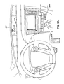
- FIG. 5A is a view of the cabin of the vehicle 100 according to an example embodiment.
- the cabin includes the accelerator 224 , the drive mode selector 226 and the display 300 .
- the relative locations of the drive mode selector 226 and the display 300 are not limited to the locations shown in FIG. 5A .
- the accelerator 224 is depicted as an accelerator pedal in FIG. 5A .
- the accelerator 224 can be omitted where the accelerator sensor 222 acts as a direct interface with a driver or computer system controlling the vehicle 100 .
- the drive mode selector 226 is a push button designated as “ECO MODE”.
- the drive mode selector 226 can be designated with other markings, such as “HMDF”.
- the HMDF mode of the present embodiment is turned on by a driver pushing and holding the drive mode selector 226 for a designated period of time, such as for two seconds. By having a period of time for which the drive mode selector 226 is depressed, it is ordinarily possible to reduce an accidental selection of the HMDF mode. However, as will be appreciated by those of ordinary skill in the art, such a user interface feature is optional. To turn off the HMDF mode, the drive mode selector 226 can be pressed again.
- FIG. 5B provides a close-up view of the display 300 which displays information for a driver when the HMDF mode has been enabled via the drive mode selector 226 .
- the display 300 includes the mode indicator 302 , the glide zone indicator 304 , the pulse zone indicator 306 , the HMDF indicator 308 , the status bar 310 , and the current zone block 312 .
- the mode indicator 302 illuminates and the HMDF indicator 308 , the status bar 310 and the current zone block 312 appear on the display 300 .
- the glide zone indicator 304 illuminates when the accelerator sensor 222 detects the accelerator input within the range of values defining the glide zone in the accelerator tuning map. In addition, the glide zone indicator 304 turns off when the accelerator sensor 222 detects the accelerator input outside of the range of values defining the glide zone.
- the pulse zone indicator 306 illuminates when the accelerator sensor 222 detects the accelerator input within the range of values defining the pulse zone.
- the pulse zone indicator 306 indicates “SWEET SPOT” to reference the efficient operation point of the vehicle 100 or the engine 204 .
- the pulse zone indicator 306 turns off when the accelerator sensor 222 detects the accelerator input outside of the range of values defining the pulse zone.
- Additional information is provided to a driver with the status bar 310 , which provides a graphical representation of the accelerator input in relation to the four zones described above.
- the current status block 312 moves along the status bar 310 to indicate the current location of the accelerator input, thereby providing the driver with information on whether the accelerator 224 is in a position corresponding to a glide, a transition, a pulse or a high power acceleration zone.
- the current status block 312 provides the driver with a sense of how close the accelerator input is to moving into a different zone, which can ordinarily allow the driver to correct the position of the accelerator 224 to reduce the chance of accidentally entering an unwanted zone.
- the status bar 310 and the indicators 302 , 304 , 306 and 308 are only examples of graphical representations for providing information in one embodiment of an HMDF mode. As will be appreciated by those of ordinary skill in the art, various other graphical representations are possible.
- FIGS. 6A and 6B comprise a flowchart depicting an example process for implementing an HMDF mode in the vehicle 100 .
- an HMDF ON signal is received by the controller 216 .
- the HMDF ON signal can be sent, for example, as a result of the drive mode selector 226 being held down.
- the processor 218 or the controller 216 enables the HMDF mode.
- the processor 218 determines whether an HMDF OFF signal has been received from the drive mode selector 226 .
- the HMDF OFF signal may come from either the drive mode selector 226 or from the vehicle 100 having been turned off.
- the processor 218 disables the HMDF mode in step 406 . If the HMDF OFF signal has not been received, the controller 216 accepts a detected accelerator input in step 408 from the accelerator sensor 222 . In addition, the controller 216 accepts a speed input from the speed sensor 228 in step 410 .
- Steps 412 to 418 are optional steps which are included if the HMDF mode includes a regeneration zone.
- the processor 218 determines whether the accepted accelerator input is within a regeneration range of values. If so, a target torque or target power is retrieved in step 414 by the processor 218 from the memory 220 . More specifically, a target torque or target power is retrieved by the processor 218 using the accelerator input accepted in step 408 , the speed input accepted in step 410 and an accelerator tuning map stored in the memory 220 .
- the processor 218 controls the engine 204 such that the internal combustion engine 206 provides limited or no torque or power while the electric motors 208 and 210 convert mechanical power from the transmission 202 into electrical power.
- the processor 218 controls the inverter box 214 to modify the converted electrical power and store it in the battery unit 212 . The process then returns to step 404 to determine whether an HMDF OFF signal has been received by the controller 216 .
- step 420 The processor 218 determines whether the accepted accelerator input is within a first range of values in step 420 .
- the first range of values corresponds to a glide zone of an accelerator tuning map stored in the memory 220 . If the accelerator input is within the first range of values, the processor 218 retrieves a target torque or target power in step 422 by using the accelerator input accepted in step 408 , the speed input accepted in step 410 and the accelerator tuning map.
- step 424 the processor 218 controls the engine 204 to provide limited or no torque or power to the transmission 202 using the target torque or target power retrieved in step 422 . Such control can be achieved by operating the engine 204 in a very low power state or by turning off the engine 204 .
- the process then returns to step 404 to determine if an HMDF OFF signal has been received.
- step 426 the processor 218 determines whether the accelerator input is within a transition range of values corresponding to a transition zone, such as transition zone 2 in FIG. 3A . If so, in step 428 , the processor 218 retrieves a target torque or target power from the memory 220 corresponding to the accepted accelerator input and the accepted speed input for the transition zone of the accelerator tuning map. As discussed above, the target torque or target power for the transition zone is proportional to the accepted accelerator input. In step 430 , the processor 218 controls the engine 204 using the retrieved target torque or target power for the transition zone. The process then returns to step 404 to determine whether an HMDF OFF signal has been received by the controller 216 .
- step 426 determines in step 426 that the accepted accelerator input is not within the transition range of values
- the process proceeds to step 432 to determine whether the accelerator input is within a second range of values corresponding to a pulse zone in an accelerator tuning map stored in the memory 220 . If so, in step 434 , the processor 218 retrieves a target torque or target power from the memory 220 corresponding to the accepted accelerator input and the accepted speed input for the pulse zone.
- step 436 the processor 218 controls the engine 204 to provide a substantially constant power for the pulse zone using the retrieved target torque or target power. The process then returns to step 404 to determine whether an HMDF OFF signal has been received by the controller 216 .
- step 432 determines in step 432 that the accepted accelerator input is not within the second range of values
- the process proceeds to step 438 to determine whether the accelerator input is within a third range of values corresponding to a high power acceleration zone in an accelerator tuning map stored in the memory 220 . If the accelerator input is within the third range of values, a target torque or target power is retrieved in step 440 by the processor 218 from the memory 220 using the accepted accelerator input from step 408 and the accepted speed input from step 410 . The target torque or target power for the high power acceleration zone is proportional to the accepted accelerator input. The processor 218 then controls the engine 204 in step 442 to provide the target torque or the target power to the transmission 202 .
- steps 440 and 442 can be removed and the HMDF mode can be disabled if the accepted accelerator input is within the third range of values.
- the process returns to step 404 after step 442 to determine whether an HMDF OFF signal has been received by the controller 216 .
- the processor 218 disables the HMDF mode in step 406 and the process ends.
- FIG. 7 is a bar graph illustrating results from a thirty-six mile test drive of a hybrid vehicle incorporating an embodiment of the present invention.
- the test course included several different types of driving conditions including freeway driving and various types of city roads having a variety of traffic patterns.
- a base driving style including light accelerations and smooth decelerations resulted in an average fuel economy of 47.5 miles per gallon while driving with an HMDF mode of the present disclosure resulted in an average fuel economy of 50.8 miles per gallon. This difference in fuel economy accounts for approximately a 7% improvement in fuel economy over the base driving style.
- a software module may reside in RAM memory, flash memory, ROM memory, EPROM memory, EEPROM memory, registers, hard disk, a removable disk, a CD-ROM, or any other form of storage medium known in the art.
- An exemplary storage medium is coupled to the processor such that the processor can read information from, and write information to, the storage medium.
- the storage medium may be integral to the processor.
- the processor and the storage medium may reside in an Application Specific Integrated Circuit (ASIC).
- ASIC Application Specific Integrated Circuit
Landscapes
- Engineering & Computer Science (AREA)
- Automation & Control Theory (AREA)
- Transportation (AREA)
- Mechanical Engineering (AREA)
- Electric Propulsion And Braking For Vehicles (AREA)
- Hybrid Electric Vehicles (AREA)
- Combined Controls Of Internal Combustion Engines (AREA)
Abstract
Description
where, r is a fuel consumption rate in grams per hour, and P is a power in kilowatts, which is provided by the
Claims (20)
Priority Applications (1)
| Application Number | Priority Date | Filing Date | Title |
|---|---|---|---|
| US13/414,638 US8768584B2 (en) | 2012-03-07 | 2012-03-07 | Drive force control for vehicle |
Applications Claiming Priority (1)
| Application Number | Priority Date | Filing Date | Title |
|---|---|---|---|
| US13/414,638 US8768584B2 (en) | 2012-03-07 | 2012-03-07 | Drive force control for vehicle |
Publications (2)
| Publication Number | Publication Date |
|---|---|
| US20130238203A1 US20130238203A1 (en) | 2013-09-12 |
| US8768584B2 true US8768584B2 (en) | 2014-07-01 |
Family
ID=49114827
Family Applications (1)
| Application Number | Title | Priority Date | Filing Date |
|---|---|---|---|
| US13/414,638 Active 2032-08-17 US8768584B2 (en) | 2012-03-07 | 2012-03-07 | Drive force control for vehicle |
Country Status (1)
| Country | Link |
|---|---|
| US (1) | US8768584B2 (en) |
Cited By (3)
| Publication number | Priority date | Publication date | Assignee | Title |
|---|---|---|---|---|
| US9766629B1 (en) | 2016-09-12 | 2017-09-19 | Ford Global Technologies, Llc | Autonomous pulse and glide system |
| WO2019037325A1 (en) * | 2017-08-22 | 2019-02-28 | 清华大学 | Energy-saving stability motion control method for networked automobile queue |
| US10752245B2 (en) * | 2016-12-08 | 2020-08-25 | Hyundai Motor Company | Auto cruise control method and system for hybrid electric vehicle |
Families Citing this family (3)
| Publication number | Priority date | Publication date | Assignee | Title |
|---|---|---|---|---|
| FR3024856B1 (en) * | 2014-08-12 | 2018-01-26 | Psa Automobiles Sa. | METHOD AND DEVICE FOR MONITORING OPERATING MODES OF A HYBRID TRANSMISSION CHAIN OF A VEHICLE, BASED ON EVOLUTION LAWS |
| FR3064574B1 (en) * | 2017-03-28 | 2020-06-12 | Renault S.A.S | METHOD FOR CONTROLLING THE TORQUE TRANSMITTED TO THE WHEELS OF AN ELECTRIC OR HYBRID VEHICLE ACCORDING TO THE ADMISSIBLE REGENERATIVE TORQUE |
| JP2024112710A (en) * | 2023-02-08 | 2024-08-21 | トヨタ自動車株式会社 | Vehicle display device, vehicle display method, and vehicle display program |
Citations (17)
| Publication number | Priority date | Publication date | Assignee | Title |
|---|---|---|---|---|
| US6246951B1 (en) * | 1999-05-06 | 2001-06-12 | Ford Global Technologies, Inc. | Torque based driver demand interpretation with barometric pressure compensation |
| EP1113943A2 (en) | 1998-09-14 | 2001-07-11 | Paice Corporation | Hybrid vehicles |
| US6350217B1 (en) | 1999-05-14 | 2002-02-26 | Bayerische Motoren Werke Aktiengesellschaft | Method for establishing a defined active relationship between the operation of the accelerator pedal and the resulting braking torque of a vehicle |
| US6367447B1 (en) * | 2001-02-21 | 2002-04-09 | Ford Global Technologies, Inc. | Adjustment of driver demand for atmospheric conditions |
| US6565482B2 (en) | 1999-04-01 | 2003-05-20 | Komatsu Ltd. | Working vehicle and vehicle speed control method thereof, variable power engine and power setting method thereof, and vehicle with variable power engine and power control method thereof |
| US6953023B2 (en) | 2003-09-05 | 2005-10-11 | Ford Global Technologies, Llc | Acceleration pedal interpretation when engine torque is limited |
| US20070255478A1 (en) * | 2006-04-28 | 2007-11-01 | Honda Motor Co., Ltd. | Running control apparatus for vehicle |
| US20100042280A1 (en) | 2008-08-08 | 2010-02-18 | MAGNETIC MARELLI S.p.A | Control method and unit of an electric traction motorcycle according to the position of an accelerator grip |
| US20100191403A1 (en) | 2009-01-29 | 2010-07-29 | General Motors Corporation | System and method for communicating with a vehicle about then-current vehicle operating conditions using a telematics unit |
| US20110054768A1 (en) | 2009-08-27 | 2011-03-03 | Sullivan Joshua Ward | Systems and methods for optimizing vehicle fuel efficiency |
| US20110125294A1 (en) | 2008-07-03 | 2011-05-26 | Fuel Saving Technologies, Llc | Energy conservation systems and methods |
| US20110130901A1 (en) | 2006-12-11 | 2011-06-02 | Magna Steyr Fahrzeugtechnik Ag & Co. Kg | Method for controlling the hybrid drive of a motor vehicle and control system |
| US7954579B2 (en) | 2008-02-04 | 2011-06-07 | Illinois Institute Of Technology | Adaptive control strategy and method for optimizing hybrid electric vehicles |
| US7969291B2 (en) | 2008-08-05 | 2011-06-28 | Toyota Motor Engineering & Manufacturing North America, Inc. | Fuel enrichment indicator |
| US20110166774A1 (en) | 2010-08-26 | 2011-07-07 | Ford Global Technologies, Llc | Conservational vehicle routing |
| US8007401B2 (en) | 2007-05-02 | 2011-08-30 | Nissan Motor Co., Ltd. | Hybrid vehicle drive control apparatus and method |
| US20110213516A1 (en) | 2010-02-26 | 2011-09-01 | Gm Global Technology Operations, Inc. | Heel and toe driving on fuel cell vehicle |
-
2012
- 2012-03-07 US US13/414,638 patent/US8768584B2/en active Active
Patent Citations (18)
| Publication number | Priority date | Publication date | Assignee | Title |
|---|---|---|---|---|
| EP1113943A2 (en) | 1998-09-14 | 2001-07-11 | Paice Corporation | Hybrid vehicles |
| US6565482B2 (en) | 1999-04-01 | 2003-05-20 | Komatsu Ltd. | Working vehicle and vehicle speed control method thereof, variable power engine and power setting method thereof, and vehicle with variable power engine and power control method thereof |
| US6246951B1 (en) * | 1999-05-06 | 2001-06-12 | Ford Global Technologies, Inc. | Torque based driver demand interpretation with barometric pressure compensation |
| US6350217B1 (en) | 1999-05-14 | 2002-02-26 | Bayerische Motoren Werke Aktiengesellschaft | Method for establishing a defined active relationship between the operation of the accelerator pedal and the resulting braking torque of a vehicle |
| US6367447B1 (en) * | 2001-02-21 | 2002-04-09 | Ford Global Technologies, Inc. | Adjustment of driver demand for atmospheric conditions |
| US6953023B2 (en) | 2003-09-05 | 2005-10-11 | Ford Global Technologies, Llc | Acceleration pedal interpretation when engine torque is limited |
| US20070255478A1 (en) * | 2006-04-28 | 2007-11-01 | Honda Motor Co., Ltd. | Running control apparatus for vehicle |
| JP2007296976A (en) | 2006-04-28 | 2007-11-15 | Honda Motor Co Ltd | Vehicle travel control device |
| US20110130901A1 (en) | 2006-12-11 | 2011-06-02 | Magna Steyr Fahrzeugtechnik Ag & Co. Kg | Method for controlling the hybrid drive of a motor vehicle and control system |
| US8007401B2 (en) | 2007-05-02 | 2011-08-30 | Nissan Motor Co., Ltd. | Hybrid vehicle drive control apparatus and method |
| US7954579B2 (en) | 2008-02-04 | 2011-06-07 | Illinois Institute Of Technology | Adaptive control strategy and method for optimizing hybrid electric vehicles |
| US20110125294A1 (en) | 2008-07-03 | 2011-05-26 | Fuel Saving Technologies, Llc | Energy conservation systems and methods |
| US7969291B2 (en) | 2008-08-05 | 2011-06-28 | Toyota Motor Engineering & Manufacturing North America, Inc. | Fuel enrichment indicator |
| US20100042280A1 (en) | 2008-08-08 | 2010-02-18 | MAGNETIC MARELLI S.p.A | Control method and unit of an electric traction motorcycle according to the position of an accelerator grip |
| US20100191403A1 (en) | 2009-01-29 | 2010-07-29 | General Motors Corporation | System and method for communicating with a vehicle about then-current vehicle operating conditions using a telematics unit |
| US20110054768A1 (en) | 2009-08-27 | 2011-03-03 | Sullivan Joshua Ward | Systems and methods for optimizing vehicle fuel efficiency |
| US20110213516A1 (en) | 2010-02-26 | 2011-09-01 | Gm Global Technology Operations, Inc. | Heel and toe driving on fuel cell vehicle |
| US20110166774A1 (en) | 2010-08-26 | 2011-07-07 | Ford Global Technologies, Llc | Conservational vehicle routing |
Cited By (3)
| Publication number | Priority date | Publication date | Assignee | Title |
|---|---|---|---|---|
| US9766629B1 (en) | 2016-09-12 | 2017-09-19 | Ford Global Technologies, Llc | Autonomous pulse and glide system |
| US10752245B2 (en) * | 2016-12-08 | 2020-08-25 | Hyundai Motor Company | Auto cruise control method and system for hybrid electric vehicle |
| WO2019037325A1 (en) * | 2017-08-22 | 2019-02-28 | 清华大学 | Energy-saving stability motion control method for networked automobile queue |
Also Published As
| Publication number | Publication date |
|---|---|
| US20130238203A1 (en) | 2013-09-12 |
Similar Documents
| Publication | Publication Date | Title |
|---|---|---|
| US8565952B2 (en) | Forward-looking hybrid vehicle control strategy | |
| JP5198147B2 (en) | VEHICLE, ITS CONTROL METHOD AND DRIVE DEVICE | |
| US9108629B2 (en) | Driving assistance device | |
| CN103171548B (en) | Method and system for the conversion of control model in hybrid electric vehicle | |
| CN101765531B (en) | Driving force controller of vehicle | |
| JP4577582B2 (en) | Hybrid vehicle power control system | |
| US8768584B2 (en) | Drive force control for vehicle | |
| CN103068651B (en) | Vehicle and control method | |
| US11904834B2 (en) | Control device and control method for series hybrid vehicle | |
| US9457664B2 (en) | Display device | |
| US9527502B1 (en) | Method and apparatus for controlling plug-in hybrid electric vehicle | |
| JP2009298232A (en) | Hybrid vehicle and control method thereof | |
| CN115667036A (en) | Systems and methods for using peak power in a targeted manner | |
| JP2016193686A (en) | Control device for hybrid vehicle | |
| JP2016046919A (en) | Automobile | |
| JP2013162618A (en) | Power consumption rate calculating device for vehicle | |
| CN114286768B (en) | Control method of series hybrid vehicle and series hybrid vehicle | |
| JP6048355B2 (en) | Power generation control device | |
| US11767039B2 (en) | Hybrid vehicle | |
| WO2012137301A1 (en) | Vehicle and method for controlling same | |
| JP2009001097A (en) | Vehicle and control method thereof | |
| US20230303059A1 (en) | Series hybrid vehicle control method and series hybrid vehicle control device | |
| JP5221068B2 (en) | Vehicle control device | |
| JP2009040275A (en) | Braking / driving force control device for vehicle | |
| JP2009002282A (en) | Braking / driving force control device |
Legal Events
| Date | Code | Title | Description |
|---|---|---|---|
| AS | Assignment |
Owner name: TOYOTA MOTOR ENGINEERING & MANUFACTURING NORTH AME Free format text: ASSIGNMENT OF ASSIGNORS INTEREST;ASSIGNOR:DUFFORD, MOHAMMAD E.;REEL/FRAME:027968/0359 Effective date: 20120306 |
|
| STCF | Information on status: patent grant |
Free format text: PATENTED CASE |
|
| AS | Assignment |
Owner name: TOYOTA JIDOSHA KABUSHIKI KAISHA, JAPAN Free format text: ASSIGNMENT OF ASSIGNORS INTEREST;ASSIGNOR:TOYOTA MOTOR ENGINEERING & MANUFACTURING NORTH AMERICA, INC.;REEL/FRAME:033138/0157 Effective date: 20140617 |
|
| MAFP | Maintenance fee payment |
Free format text: PAYMENT OF MAINTENANCE FEE, 4TH YEAR, LARGE ENTITY (ORIGINAL EVENT CODE: M1551) Year of fee payment: 4 |
|
| MAFP | Maintenance fee payment |
Free format text: PAYMENT OF MAINTENANCE FEE, 8TH YEAR, LARGE ENTITY (ORIGINAL EVENT CODE: M1552); ENTITY STATUS OF PATENT OWNER: LARGE ENTITY Year of fee payment: 8 |
|
| FEPP | Fee payment procedure |
Free format text: MAINTENANCE FEE REMINDER MAILED (ORIGINAL EVENT CODE: REM.); ENTITY STATUS OF PATENT OWNER: LARGE ENTITY |