US8768507B2 - Robot and behavior control system for the same - Google Patents
Robot and behavior control system for the same Download PDFInfo
- Publication number
- US8768507B2 US8768507B2 US13/237,018 US201113237018A US8768507B2 US 8768507 B2 US8768507 B2 US 8768507B2 US 201113237018 A US201113237018 A US 201113237018A US 8768507 B2 US8768507 B2 US 8768507B2
- Authority
- US
- United States
- Prior art keywords
- robot
- state variables
- state
- specified
- control system
- Prior art date
- Legal status (The legal status is an assumption and is not a legal conclusion. Google has not performed a legal analysis and makes no representation as to the accuracy of the status listed.)
- Active, expires
Links
Images


Classifications
-
- B—PERFORMING OPERATIONS; TRANSPORTING
- B62—LAND VEHICLES FOR TRAVELLING OTHERWISE THAN ON RAILS
- B62D—MOTOR VEHICLES; TRAILERS
- B62D57/00—Vehicles characterised by having other propulsion or other ground- engaging means than wheels or endless track, alone or in addition to wheels or endless track
- B62D57/02—Vehicles characterised by having other propulsion or other ground- engaging means than wheels or endless track, alone or in addition to wheels or endless track with ground-engaging propulsion means, e.g. walking members
- B62D57/032—Vehicles characterised by having other propulsion or other ground- engaging means than wheels or endless track, alone or in addition to wheels or endless track with ground-engaging propulsion means, e.g. walking members with alternately or sequentially lifted supporting base and legs; with alternately or sequentially lifted feet or skid
Definitions
- the present invention relates to a legged mobile robot which has a body, an arm connected to the body, and a plurality of legs supporting the body, and a system which controls the behavior of the legged mobile robot.
- Controlling the motion of a robot body, which includes the base body and arms, by giving priority to causing the robot to carry out a task may lead to inappropriate position and posture of the body relative to its legs in continuing stable gaits for the robot.
- the present invention has been made, therefore, to mainly provide a robot capable of continuously maintaining stability while carrying out a specified task by moving its body.
- the present invention relates to a robot provided with a body, an arm connected to the body, a plurality of legs supporting the body, and a behavior control system constructed to control the motion of each of the body, the arm, and the plurality of legs according to a desired motion trajectory.
- a robot in accordance with the present invention has the behavior control system configured to generate time-series changing patterns of first state variables and second state variables, respectively, as the desired motion trajectories according to a stochastic transition model, which expresses the first state variables indicating a motional state of the arm and the second state variables indicating a motional state of the body, which are variation factors of the values of the first state variables, as random variables, such that at least one of the first state variables follows a first specified motion trajectory determined for the robot to carry out a specified task and the second state variables cause the robot to satisfy a continuously stable dynamic condition.
- a stochastic transition model which expresses the first state variables indicating a motional state of the arm and the second state variables indicating a motional state of the body, which are variation factors of the values of the first state variables, as random variables, such that at least one of the first state variables follows a first specified motion trajectory determined for the robot to carry out a specified task and the second state variables cause the robot to satisfy a continuously stable dynamic condition
- the time-series changing patterns of the first state variables (the first desired motion trajectories), which denote the motional state of the arm, are generated on the basis of the stochastic transition model such that at least one of the first state variables follows the first specified motion trajectory for causing the robot to carry out a specified task.
- the time-series changing patterns of the second state variables (the second desired motion trajectories), which denote the motional state of the body, are generated on the basis of the stochastic transition model such that the second state variables satisfy a continuously stable dynamic condition.
- the second state variables are variation factors of the values of the first state variables, so that generating the continuously stable second desired motion trajectories may make it difficult for the first state variables to closely follow the first specified motion trajectories.
- the first state variables are expressed as the random variables, so that the level of follow-up (the level of observance) of at least one of the first state variables relative to the first specified motion trajectory can be flexibly adjusted under a condition that the robot carries out a specified task.
- the first state variables are required to relatively closely coincide with or approximate to the first specified motion trajectories.
- the first state variables are allowed to deviate from the first specified motion trajectories to a certain degree.
- the motion of the entire robot is controlled to ensure continuous stability while carrying out the specified task by a motion of the body of the robot.
- the desired motion trajectory may be generated according to the stochastic transition model to which a variation based on an external force applied to the robot from the object during the period of the interaction between the body and the object has been added.
- the overall motion of the robot can be controlled to permit continued stability while at the same time having the robot carry out a specified task involving the interaction with the object.
- the behavior control system may alternatively be configured to generate the desired motion trajectory according to the stochastic transition model in which at least one probability distribution in the random variable is expressed by a truncated distribution.
- At least one probability distribution out of the state variables expressed as random variables in the stochastic transition model is expressed by a truncated distribution.
- the truncated distribution means a probability distribution in which a state variable value range wherein probabilities take positive values and a state variable value range wherein the probability becomes zero are adjacent to each other.
- the overall motion of the robot can be controlled to satisfy the aforesaid condition by matching the range of numerical values that cannot be taken by the aforesaid state variables with the state variable value range in which the probability becomes zero in the truncated distribution.
- FIG. 1 is an illustration diagram of the construction of a robot as an embodiment in accordance with the present invention
- FIG. 2 is a block diagram of a control system of the robot as the embodiment in accordance with the present invention.
- FIG. 3 is an illustration diagram of a simplified model showing a behavior of the robot
- FIG. 4 is an explanatory diagram of a stochastic transition model in a first embodiment
- FIG. 5 is a flowchart illustrating a method for controlling the behavior of the robot in the first embodiment
- FIG. 6 is an explanatory diagram illustrating a desired motion trajectory
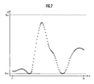
- FIG. 7 is an explanatory diagram illustrating the limit of an arm length
- FIG. 8( a ) and FIG. 8( b ) are explanatory diagrams illustrating the limits of joint angles
- FIG. 9( a ), FIG. 9( b ) and FIG. 9( c ) are diagrams illustrating a specified task of the robot in the first embodiment
- FIG. 10 is an explanatory diagram of a stochastic transition model in a second embodiment
- FIG. 11 is a flowchart illustrating a method for controlling the behavior of a robot in the second embodiment
- FIG. 12( a ), FIG. 12( b ) and FIG. 12( c ) are diagrams illustrating a specified task of the robot in the second embodiment
- FIG. 13 is an illustration diagram of another simplified model showing a behavior of a robot
- FIG. 14 is an explanatory diagram illustrating a stochastic transition model in another embodiment.
- FIG. 15 is an explanatory diagram illustrating a desired motion trajectory in another embodiment.
- a robot 1 shown in FIG. 1 is a legged mobile robot and provided with a body 10 , a head 11 mounted on the top of the body 10 , right and left arms 12 extended from the right and left sides of an upper portion of the body 10 , hands 13 provided at the distal ends of the arms 12 , right and left legs 14 extended downward from the bottom of the body 10 , and feet 15 attached to the distal ends of the legs 14 , as with a human being.
- the robot 1 is capable of bending and stretching the arms 12 and the legs 14 at a plurality of joint mechanisms corresponding to a plurality of joints, such as shoulder joints, elbow joints, wrist joints, hip joints, knee joint, and ankle joints of a human being by forces transmitted from actuators 24 .
- Each of the arms 12 has a first arm link connected to the body 10 through the intermediary of a shoulder joint mechanism and a second arm link having one end thereof connected to an end of the first arm link through the intermediary of an elbow joint mechanism and the other end thereof connected to the base of the hand 13 through the intermediary of a wrist joint.
- Each of the shoulder joint mechanisms has two freedom degrees of rotation about a yaw axis and a pitch axis.
- the elbow joint mechanism has one freedom degree of rotation about the pitch axis.
- the wrist joint mechanism has two freedom degrees of rotation about a roll axis and the pitch axis.
- Each of the legs 14 has a first leg link connected to the body 10 through the intermediary of a hip joint mechanism and a second leg link having one end connected to an end of the first leg link through the intermediary of a knee joint mechanism while the other end connected to the foot 15 through the intermediary of an ankle joint.
- the hip joint mechanism has three freedom degrees of rotation about the yaw axis, the pitch axis and the roll axis.
- the knee joint mechanism has one freedom degree of rotation about the pitch axis.
- the ankle joint mechanism has two freedom degrees of rotation about the pitch axis and the roll axis.
- the robot 1 is capable of autonomously moving by repeatedly leaving and landing the right and left legs 14 from and onto a floor.
- a behavior control system 2 illustrated in FIG. 2 is constituted of an electronic control unit, which is composed primarily of a CPU, a ROM, a RAM, and I/O circuits, or a computer, which is mounted in the robot 1 .
- the behavior control system 2 is configured to recognize the values of a variety of state variables on the basis of output signals from an internal state sensor group 21 and an external state sensor group 22 , respectively.
- the internal state sensor group 21 includes, a GPS measuring instrument for measuring the position (the position of the center of gravity) of the robot 1 or an acceleration sensor, and further, a gyro sensor for measuring the posture of the body 10 , rotary encoders for measuring the bending angles or the like of joint mechanisms, and the like.
- the external state sensor group 22 includes, for example, a motion capture system (not shown), which is separate from and independent of the robot 1 , a stereo image sensor mounted on the head 11 to measure the positional trajectory of an object, such as a ball, related to the execution of a task, an active sensor using infrared light mounted on the body 10 , and the like.
- a motion capture system (not shown), which is separate from and independent of the robot 1
- a stereo image sensor mounted on the head 11 to measure the positional trajectory of an object, such as a ball, related to the execution of a task
- an active sensor using infrared light mounted on the body 10 , and the like.
- the behavior control system 2 is configured to generate the time-series changing patterns of the first state variables and the second state variables, respectively, in the form of desired motion trajectories according to a stochastic transition model, which will be discussed hereinafter.
- the first state variables denote the motional states of the arms 12 and the hands 13 .
- the second state variables denote the motional states of the body of the robot 1 .
- the behavior control system 2 is configured to control the motional modes of the robot 1 according to a desired motion trajectory by controlling the operations of the actuators 24 on the basis of the recognition results of state variables.
- the behavior control system 2 is configured” means that the behavior control system 2 reads required software and data from a storage means, such as a memory, carries out arithmetic processing on the data according to the software, generates a control command signal based on the result of the arithmetic processing, and outputs the signal to a control target, thereby fulfilling a purpose, such as controlling the behavior of the robot 1 .
- a storage means such as a memory
- a constituent device in the present invention “recognizes,” it means that the constituent device executes every information processing required for the preparation to subject the information to further arithmetic processing.
- Such information processing includes, for example, searching information from a database, reading information from a storage, such as a memory, measuring, calculating, estimating or determining information on the basis of output signals of sensors or the like, and storing the information, which has been measured or the like, in a memory.
- Some constituent devices, such as the state recognizing device 110 and the trajectory generating device 120 , of the behavior control system 2 may be constructed of an external computer of the robot 1 , and the rest, such as a device for controlling the behaviors of the robot 1 , may be constructed of a computer capable of receiving calculation results from the external computer in a wireless or wired manner.
- the stochastic transition model in a first embodiment of the present invention is made on the basis of a concept that a behavior of the robot 1 is expressed in a simplified manner by the behavior of each of an inverted pendulum and an arm extended from a mass point or an upper end of the inverted pendulum, as illustrated in FIG. 3 .
- the inverted pendulum is assumed to have a constant height h, and assumed to be rockable about the roll axis and the pitch axis, respectively, the lower end thereof being the supporting point.
- the ZMP means a point of action obtained by replacing a normal line component of a floor reaction force applied such that the floor reaction force is distributed over the entire foot 15 by one point assumed to be subjected to the overall floor reaction force.
- horizontal means that the physical quantity of an object is denoted by two directional components that are perpendicular to the yaw axis of a global coordinate system. If the term “horizontal” is not added, then it means that the physical quantity of an object is denoted by three directional components of the global coordinate system that are perpendicular to each other.
- the state variables (x, v) denoting the behavior states of the inverted pendulum correspond to the second state variables that denote the motional states of the body of the robot 1 .
- the arm is composed of three links connected in order from the upper end of the inverted pendulum.
- the three links correspond to a first arm link and a second arm link of the arm 12 of the robot 1 , and the hand 13 , respectively.
- angles of rotation about two orthogonal axes of the shoulder joint mechanism that define the posture of the first arm link relative to the body 10 are denoted by the angles of rotation ( ⁇ 1 , ⁇ 1 ) about two orthogonal axes of the first link of the arm relative to the inverted pendulum.
- the angle of rotation about one axis of the elbow joint mechanism that defines the posture of the second arm link relative to the first arm link is denoted by an angle of rotation ⁇ 2 about one axis of the second link relative to the first link of the arm.
- angles of rotation about two orthogonal axes of the wrist joint mechanism that define the posture of the hand 13 relative to the second arm link are denoted by the angles of rotation ( ⁇ 3 , ⁇ 2 ) about two orthogonal axes of the third link relative to the second link of the arm.
- a distance d from the base thereof to the distal end position thereof is considered.
- the state variables (y 1 , y 2 , y 3 ) indicating the behavior of the arm correspond to the first state variables indicating the motional states of the arm 12 of the robot 1 .
- the stochastic transition model is expressed by the dynamics Bayesian network (DBN) shown in FIG. 4 .
- DBN dynamics Bayesian network
- the aforesaid inverted pendulum that expresses the behaviors of the robot 1 in a simplified manner and the dynamic equations and the control laws of the arms are represented by a plurality of nodes (circles), which denote the state variables at each time point t as random variables, and the arrows which connect the nodes.
- the dynamic equations and the control laws of the robot 1 are represented by relational expressions (11) to (14).
- Relational expression (11) indicates a control law whereby the horizontal position z of the ZMP follows the desired horizontal position trajectory u (corresponding to the second specified motion trajectory) of the body so as to prevent the robot 1 from diverging.
- the divergence of the robot 1 means that the balance thereof is disrupted to an extent that the robot 1 is very likely to fall. Hence, considerations are given to a divergent component to restrain the divergence.
- the value of the divergent component of the robot 1 is a numeric value that indicates the separation of the position of the body 10 of the robot 1 from the positions of both feet 15 (more specifically, the origin of a global coordinate system (a supporting leg coordinate system) set on the ground contact surface of a supporting leg foot 15 ) (refer to official gazettes related to the present applicant's ownership, such as Japanese Patents No. 3672100 and No. 3674788).
- the divergent component is represented by relational expression (01) using a body mass point horizontal position x, a body mass point horizontal velocity v, and a predetermined constant (e.g., the natural frequency of the inverted pendulum) ⁇ 0 .
- (Divergent component) x+v/ ⁇ 0 (01)
- the horizontal position z of the ZMP of the robot 1 is represented by relational expression (02) using the desired portion trajectory u of the body, the body mass point horizontal position x, the body mass point horizontal velocity v, a feedback coefficient k, and the natural frequency of the inverted pendulum ⁇ 0 .
- z ( ⁇ u ⁇ k /( k+ 1)+ x+v/ ⁇ 0 )( ⁇ 0 +k ⁇ 0 ) ⁇ t /(1 ⁇ exp( ⁇ 0 ⁇ t )) (02)
- the distance d from the base to the distal end position of the arm is a random variable, the probability distribution of which is represented by a truncated distribution in which the probability becomes zero outside the permissible range of the distance from the shoulder joint mechanism of the robot 1 to the distal end of the hand 13 .
- DK in the right side of relational expression (14) denotes a function indicating a forward kinematic or geometric relationship to calculate the positions of the distal ends of the first to the third links, respectively, of the arm on the basis of the joint angle p.
- the robot 1 carries out a specified task of swinging a racket held by one of the hands 13 by a forehand stroke.
- a first specified motion trajectory ⁇ r ⁇ [r(t 1 ), . . . r(t 1 +(i ⁇ 1) ⁇ t), r(t 1 +i ⁇ t), r(t 1 +(i+1) ⁇ t), . . . r(t 2 )] established to cause the robot 1 to carry out the specified task is recognized by the behavior control system 2 or a first specified motion trajectory recognizing element, which is a constituent element thereof (STEP 11 in FIG. 5 ).
- the first specified motion trajectory ⁇ r ⁇ i.e., the time-series exemplary changing pattern of the distal end position of the hand 13 , is generated by the same technique as the technique disclosed in Japanese Patent Application Laid-Open No. 2010-005761.
- the time-series changing patterns of the hand positions when an instructor (human being) carries out the specified task a plurality of times are measured by an optical, mechanical, magnetic or inertial motion capture system constituting the external state sensor group 22 .
- scaling on the basis of the difference in body size between the instructor and the robot 1 is performed, thereby generating the first specified motion trajectory.
- the first specified motion trajectory is stored in a memory device.
- a first specified motion trajectory that has been set beforehand may be transmitted to the robot 1 from an external unit, such as a remote control device, and stored in the memory device.
- first desired motion trajectory which shows the time-series desired changing pattern of the first state variable
- second desired motion trajectory which shows the time-series desired changing pattern of the second state variable
- the robot 1 As the method for the robot 1 to estimate each node in the DBN at time point t 1 at which the execution of the specified task is begun, Gibbs sampling or the like is used.
- a desired position trajectory ⁇ y 1 ⁇ of the elbow joint mechanism, a desired position trajectory ⁇ y 2 ⁇ of the wrist joint mechanism, and a desired position trajectory ⁇ y 3 ⁇ of the distal end of the hand 13 shown in FIG. 6 are generated as the first desired motion trajectories.
- the desired position trajectory ⁇ y 3 ⁇ of the distal end of the hand 13 follows the first specified motion trajectory ⁇ r ⁇ such that it substantially coincides therewith.
- a desired position trajectory ⁇ x ⁇ of the body mass point or the shoulder joint mechanism and a desired horizontal position trajectory ⁇ z ⁇ of the ZMP shown also in FIG. 6 are generated as the second desired motion trajectories.
- the desired motion trajectories are generated such that distance d between the shoulder joint mechanism and the hand 13 stays within a permissible range [d low , d up ], as illustrated in FIG. 7 .
- the desired motion trajectories are generated such that the angles of rotation ⁇ 1 and ⁇ 1 about the two orthogonal axes of the shoulder joint mechanism and the angle of rotation ⁇ 2 about one axis of the elbow joint mechanism stay within their permissible ranges [ ⁇ 1low , ⁇ 1up ], [ ⁇ 1low , ⁇ 1up ], and [ ⁇ 2low , ⁇ 2up ], respectively, as illustrated in FIG. 8( a ).
- the desired motion trajectories are generated such that the angles of rotation ⁇ 3 and ⁇ 2 about the two orthogonal axes of the wrist joint mechanism stay within their permissible ranges [ ⁇ 3low , ⁇ 3up ] and [ ⁇ 2low , ⁇ 2up ], respectively, as illustrated in FIG. 8( b ).
- the behavior control system 2 controls the motion of the robot 1 according to the desired motion trajectories (STEP 13 in FIG. 5 ). More specifically, the operations of the actuators 24 are controlled so as to control the motion of the entire robot 1 such that the positions of the elbow joint mechanism, the wrist joint mechanism, and the distal end of the hand 13 follow the first desired motion trajectories ⁇ y 1 ⁇ , ⁇ y 2 ⁇ and ⁇ y 3 ⁇ , respectively, and the positions of the shoulder joint mechanism and the ZMP follow the second desired motion trajectories ⁇ x ⁇ and ⁇ z ⁇ , respectively.
- the distal end position of the hand 13 as the first state variable changes in a time-series manner, closely following the first specified motion trajectory ⁇ r ⁇ such that it substantially coincides therewith. More specifically, the arms 12 , the legs 14 and the like are moved as illustrated in FIG. 9( a ) to FIG. 9( c ) in order, enabling the robot 1 to carry out the specified task of swinging forehand the racket held by one of the hands 13 .
- the time-series changing pattern (the first desired motion trajectory) of the first state variable denoting the motional state of the body is generated according to the stochastic transition model such that at least one of the first state variables (the position of the hand or the position of the racket) follows the first specified motion trajectory ⁇ r ⁇ for the robot 1 to carry out the specified task (refer to FIG. 6 ).
- the time-series changing pattern (the second desired motion trajectory) of the second state variable denoting the gait state of the robot 1 is generated according to the stochastic transition model such that the second state variable satisfies the dynamic condition that continuously stabilizes the robot 1 (refer to relational expression (11)).
- the second state variable is a variation factor of the value of the first state variable, so that generating the second desired motion trajectory that continuously stabilizes the robot 1 may make it difficult for the first state variable to closely follow the first specified motion trajectory.
- the first state variable is expressed as the random variable, so that the level of follow-up (the level of observance) of at least one (the position of the hand) of the first state variables relative to the first specified motion trajectory can be flexibly adjusted under a condition that the robot 1 carries out a specified task.
- the first state variable is required to relatively closely coincide with or approximate to the first specified motion trajectory ⁇ r ⁇ .
- the first state variable is allowed to deviate from the first specified motion trajectory to a certain degree.
- Desired motion trajectories are generated according to the stochastic transition model, in which the probability distribution of at least one of the random variables (the distance d between the shoulder joint mechanism and the distal end position of the hand, and the joint angle of the arm) is represented by a truncated distribution.
- the overall motion of the robot 1 can be controlled to satisfy the aforesaid condition by matching the range of numerical values that cannot be taken by the aforesaid state variables with the state variable value range in which the probability becomes zero in the truncated distribution (refer to FIG. 7 and FIGS. 8( a ) and 8 ( b )).
- a stochastic transition model in a second embodiment of the present invention is made on the basis of a concept that a behavior of the robot 1 is expressed in a simplified manner by the behavior of each of an inverted pendulum and an arm, as illustrated in FIG. 3 .
- the second embodiment differs from the first embodiment in that, in order to cause the robot 1 to carry out a specified task that involves an interaction with an object, a force applied to the robot 1 from the object by the interaction is taken into account.
- h denotes the height of the inverted pendulum
- m denotes the mass of the inverted pendulum
- g denotes the gravitational acceleration
- the robot 1 carries out a specified task of swinging a racket held by one of the hands 13 by a forehand stroke to hit a ball (object) back.
- the racket is regarded as a part of the hand 13 .
- the position of the gut of the racket (the portion where the ball is hit) held by the hand 13 (the position of the racket) is handled as a distal end position x of the hand 13 .
- the behavior control system 2 or a ball position trajectory measuring element which is a constituent element thereof measures in a time-series manner the position of the ball in a world coordinate system or a robot coordinate system on the basis of the time-series position of the ball indicated by output signals of the external state sensor group 22 (refer to STEP 21 in FIG. 11 and FIG. 12( a )).
- the behavior control system 2 or a ball position trajectory predicting element which is a constituent element thereof, predicts the position trajectory of the ball on the basis of a time-series estimated position x 1 (k) of the ball (refer to STEP 22 in FIG. 11 and the dashed line in FIG. 12( a )).
- the behavior control system 2 or an interaction point candidate setting element which is a constituent element thereof, sets an interaction point or a hitting point of the racket and the ball within a range that can be reached by the racket, i.e., the gut thereof, by a motion of the robot 1 (refer to STEP 23 in FIG. 11 and FIG. 12( a )).
- the range that can be reached by the racket is estimated according to a kinematics calculation method on the basis of the bending angles of the joint mechanisms indicated by output signals of the internal state sensor group 21 and the kinematic parameters, such as the position and the posture, of the racket relative to the hand 13 .
- the range that can be reached by the racket it is confirmed that different portions of the robot 1 , including the body 10 and the arms 12 , will not interfere or contact with each other.
- the position of the racket in a hand coordinate system, the position and the posture of which are fixed relative to the palm of the hand 13 may be set in advance, or may be sequentially calculated on the basis of the racket gripping position and posture relative to the hand 13 imaged by an image-taking device constituting the internal state sensor group 21 .
- the behavior control system 2 recognizes the first specified motion trajectory ⁇ r ⁇ indicating a time-series exemplary position trajectory of the racket position as the first state variable established to cause the robot 1 to carry out the specified task (STEP 24 in FIG. 11 ). For example, a first specified motion trajectory that passes a set interaction point at predicted time at which the ball reaches is selected from among a plurality of first specified motion trajectories stored in the memory device.
- a first desired motion trajectory indicating a time-series desired changing pattern of a first state variable and a second desired motion trajectory indicating a time-series desired changing pattern of a second state variable are generated as desired motion trajectories (STEP 25 in FIG. 11 (refer to FIG. 6 )).
- nodes that denote the force f and the ZMP-conversion result e thereof are added at least during the period of the interaction of the racket and the ball in the DBN indicating the stochastic transition model.
- the behavior control system 2 controls the motion of the robot 1 according to the desired motion trajectories (STEP 26 in FIG. 11 ). More specifically, the operations of the actuators 24 are controlled so as to control the motion of the entire robot 1 such that the positions of the elbow joint mechanism, the wrist joint mechanism, and the racket follow the first desired motion trajectories ⁇ y 1 ⁇ , ⁇ y 2 ⁇ and ⁇ y 3 ⁇ , respectively, and the positions of the shoulder joint mechanism and the ZMP follow the second desired motion trajectories ⁇ x ⁇ and ⁇ z ⁇ , respectively.
- the racket position as the first state variable changes in a time-series manner, closely following the first specified motion trajectory ⁇ r ⁇ such that it substantially coincides therewith. More specifically, the arms 12 , the legs 14 and the like are moved as illustrated in FIG. 12( a ) to FIG. 12( c ) in order, enabling the robot 1 to carry out the specified task of swinging forehand the racket held by one of the hands 13 to hit the ball back.
- Other specified tasks involving steady interactions between the body and an object can be carried out in addition to a specified task that involves a temporary interaction between the body and an object, including a specified task of catching an object, such as a ball, coming toward the robot 1 by the hand or hands 13 thereof.
- the robot 1 or the behavior control system 2 as the second embodiment of the present invention displaying the functions described above provides the same operations and effects as those of the first embodiment of the present invention.
- desired motion trajectories are generated according to a stochastic transition model in which a variation e based on an external force f applied to the robot 1 from the ball is added to at least one (a horizontal position z of the ZMP) of the second state variables (refer to relational expression (21) and FIG. 10 ).
- the overall motion of the robot 1 can be controlled so as to continue stable gaits while at the same carrying out a specified task involving the interaction with an object by a motion of the body of the robot 1 (refer to FIG. 12( a ) to FIG. 12( c )).
- a stochastic transition model in another embodiment of the present invention is built on the basis of the concept that the behaviors of a robot 1 are expressed in a simplified manner by the behaviors of an inverted pendulum illustrated in FIG. 13 and an arm extended from the mass point or the upper end of the inverted pendulum, as with the first and the second embodiments.
- This embodiment differs from the first and the second embodiments in that the arm thereof is straight and a length d thereof is variable.
- the stochastic transition model in this case is expressed by a dynamics Bayesian network (DBN) illustrated in FIG. 14 .
- Relational expression (34) is applied in place of relational expression (14) representing the dynamic equation and the control law of the robot 1 in the first embodiment.
- y[i] x[i]+DK ( ⁇ 1 , ⁇ 1 ) (34)
- a desired position trajectory ⁇ y ⁇ of the distal end of a hand 13 illustrated in FIG. 15 is generated as a first desired motion trajectory.
- the desired position trajectory ⁇ y ⁇ of the distal end of the hand 13 follows a first specified motion trajectory ⁇ r ⁇ such that it substantially coincides therewith.
- a desired position trajectory ⁇ x ⁇ of a body mass point or a shoulder joint mechanism and a desired horizontal position trajectory ⁇ z ⁇ of a ZMP illustrated in FIG. 15 are generated as second desired motion trajectories. It is seen from FIG. 15 that the desired horizontal position trajectory ⁇ z ⁇ changes, following a desired horizontal position trajectory ⁇ u ⁇ of a virtual ZMP as a second specified motion trajectory.
- a behavior control system 2 controls the operations of actuators 24 such that the position of the distal end of the hand 13 follows the first desired motion trajectory ⁇ y ⁇ and the positions of the shoulder joint mechanism and the ZMP follow the second desired motion trajectories ⁇ x ⁇ and ⁇ z ⁇ , respectively, thereby controlling the motion of the entire robot 1 .
- the operations of an elbow joint mechanism and a wrist joint mechanism can be controlled to cause the robot 1 to carry out a specified task according to an inverse kinematics model that makes it possible to calculate the rotational angle of each of the elbow joint mechanism, the wrist joint mechanism and the like from the position of the shoulder joint mechanism, the position of a hand and the like.
Abstract
Description
z[i]=(−u[i]k/(k+1)+x[i−1]+v[i−1]/ω0)(ω0 +kω 0)Δt/(1−exp(−ω0 Δt) (11)
v[i]=v[i−1]+ω0ω0(x[i−1]−z[i])Δt (12)
x[i]=x[i−1]+v[i]Δt (13)
y[i]=x[i]+DK(θ1,Ψ1,θ2,θ3,Ψ2) (14)
(Divergent component)=x+v/ω 0 (01)
z=(−u·k/(k+1)+x+v/ω 0)(ω0 +k·ω 0)Δt/(1−exp(−ω0 Δt)) (02)
y[i]=x[i]+DK(θ1,ψ1) (34)
Claims (4)
Applications Claiming Priority (2)
| Application Number | Priority Date | Filing Date | Title |
|---|---|---|---|
| JP2010-216043 | 2010-09-27 | ||
| JP2010216043A JP5465142B2 (en) | 2010-09-27 | 2010-09-27 | Robot and its action control system |
Publications (2)
| Publication Number | Publication Date |
|---|---|
| US20120078416A1 US20120078416A1 (en) | 2012-03-29 |
| US8768507B2 true US8768507B2 (en) | 2014-07-01 |
Family
ID=45871435
Family Applications (1)
| Application Number | Title | Priority Date | Filing Date |
|---|---|---|---|
| US13/237,018 Active 2032-08-07 US8768507B2 (en) | 2010-09-27 | 2011-09-20 | Robot and behavior control system for the same |
Country Status (2)
| Country | Link |
|---|---|
| US (1) | US8768507B2 (en) |
| JP (1) | JP5465142B2 (en) |
Cited By (1)
| Publication number | Priority date | Publication date | Assignee | Title |
|---|---|---|---|---|
| US20180246963A1 (en) * | 2015-05-01 | 2018-08-30 | Smiths Detection, Llc | Systems and methods for analyzing time series data based on event transitions |
Families Citing this family (9)
| Publication number | Priority date | Publication date | Assignee | Title |
|---|---|---|---|---|
| US8527217B2 (en) * | 2009-09-08 | 2013-09-03 | Dynamic Athletic Research Institute, Llc | Apparatus and method for physical evaluation |
| JP5465142B2 (en) * | 2010-09-27 | 2014-04-09 | 本田技研工業株式会社 | Robot and its action control system |
| EP2610637B1 (en) * | 2011-12-28 | 2015-10-14 | AIRBUS HELICOPTERS DEUTSCHLAND GmbH | Proximity warning system for helicopters |
| US10152117B2 (en) * | 2014-08-07 | 2018-12-11 | Intel Corporation | Context dependent reactions derived from observed human responses |
| JP6228097B2 (en) * | 2014-10-06 | 2017-11-08 | 本田技研工業株式会社 | Mobile robot |
| JP5927270B2 (en) * | 2014-11-06 | 2016-06-01 | ファナック株式会社 | Robot simulation device |
| US11312018B2 (en) * | 2014-11-14 | 2022-04-26 | Transportation Ip Holdings, Llc | Control system with task manager |
| JP6567998B2 (en) * | 2016-03-23 | 2019-08-28 | 国立大学法人 東京大学 | Control method |
| JP7415693B2 (en) | 2020-03-13 | 2024-01-17 | オムロン株式会社 | Hitting style determining device, batting style determining method, batting style determining program, and ball return robot |
Citations (10)
| Publication number | Priority date | Publication date | Assignee | Title |
|---|---|---|---|---|
| US7139740B2 (en) * | 2003-01-17 | 2006-11-21 | Ayala Francisco J | System and method for developing artificial intelligence |
| JP2007160428A (en) | 2005-12-12 | 2007-06-28 | Honda Motor Co Ltd | Walking figure generating device of legged mobile robot |
| JP2008142861A (en) | 2006-12-12 | 2008-06-26 | Toyota Motor Corp | Gait data production device and gait data production method |
| US20080312772A1 (en) * | 2007-06-14 | 2008-12-18 | Honda Motor Co., Ltd. | Motion control system, motion control method, and motion control program |
| US20090326710A1 (en) * | 2008-06-27 | 2009-12-31 | Honda Motor Co., Ltd. | Behavior control system |
| US20090326679A1 (en) * | 2008-06-27 | 2009-12-31 | Honda Motor Co., Ltd. | Behavior estimating system |
| US20110160908A1 (en) * | 2009-12-24 | 2011-06-30 | Honda Motor Co., Ltd. | Behavior control system and robot |
| US20110257764A1 (en) * | 2005-03-31 | 2011-10-20 | Massachusetts Institute Of Technology | Powered ankle-foot prothesis |
| US20120078416A1 (en) * | 2010-09-27 | 2012-03-29 | Honda Motor Co., Ltd. | Robot and behavior control system for the same |
| US8527217B2 (en) * | 2009-09-08 | 2013-09-03 | Dynamic Athletic Research Institute, Llc | Apparatus and method for physical evaluation |
Family Cites Families (4)
| Publication number | Priority date | Publication date | Assignee | Title |
|---|---|---|---|---|
| JP2003117858A (en) * | 1999-09-20 | 2003-04-23 | Sony Corp | Method and device for control of robot walk |
| JP2004180817A (en) * | 2002-12-02 | 2004-07-02 | National Institute Of Advanced Industrial & Technology | Work supporting manipulator system using biological signal |
| JP4143103B2 (en) * | 2006-12-20 | 2008-09-03 | 本田技研工業株式会社 | MOBILE DEVICE, ITS CONTROL SYSTEM, CONTROL PROGRAM, AND SUPERVISION SYSTEM |
| JP4780147B2 (en) * | 2008-06-16 | 2011-09-28 | トヨタ自動車株式会社 | Legged robot and walking control method for legged robot |
-
2010
- 2010-09-27 JP JP2010216043A patent/JP5465142B2/en active Active
-
2011
- 2011-09-20 US US13/237,018 patent/US8768507B2/en active Active
Patent Citations (16)
| Publication number | Priority date | Publication date | Assignee | Title |
|---|---|---|---|---|
| US7139740B2 (en) * | 2003-01-17 | 2006-11-21 | Ayala Francisco J | System and method for developing artificial intelligence |
| US8512415B2 (en) * | 2005-03-31 | 2013-08-20 | Massachusetts Institute Of Technology | Powered ankle-foot prothesis |
| US20110257764A1 (en) * | 2005-03-31 | 2011-10-20 | Massachusetts Institute Of Technology | Powered ankle-foot prothesis |
| JP2007160428A (en) | 2005-12-12 | 2007-06-28 | Honda Motor Co Ltd | Walking figure generating device of legged mobile robot |
| JP2008142861A (en) | 2006-12-12 | 2008-06-26 | Toyota Motor Corp | Gait data production device and gait data production method |
| US20080312772A1 (en) * | 2007-06-14 | 2008-12-18 | Honda Motor Co., Ltd. | Motion control system, motion control method, and motion control program |
| JP2008307640A (en) | 2007-06-14 | 2008-12-25 | Honda Motor Co Ltd | Motion control system, motion control method, and motion control program |
| US20090326679A1 (en) * | 2008-06-27 | 2009-12-31 | Honda Motor Co., Ltd. | Behavior estimating system |
| JP2010005761A (en) | 2008-06-27 | 2010-01-14 | Honda Motor Co Ltd | Behavior control system |
| US20090326710A1 (en) * | 2008-06-27 | 2009-12-31 | Honda Motor Co., Ltd. | Behavior control system |
| US8078321B2 (en) * | 2008-06-27 | 2011-12-13 | Honda Motor Co., Ltd. | Behavior control system |
| US8099374B2 (en) * | 2008-06-27 | 2012-01-17 | Honda Motor Co., Ltd. | Behavior estimating system |
| US8527217B2 (en) * | 2009-09-08 | 2013-09-03 | Dynamic Athletic Research Institute, Llc | Apparatus and method for physical evaluation |
| US20110160908A1 (en) * | 2009-12-24 | 2011-06-30 | Honda Motor Co., Ltd. | Behavior control system and robot |
| US8660699B2 (en) * | 2009-12-24 | 2014-02-25 | Honda Motor Co., Ltd. | Behavior control system and robot |
| US20120078416A1 (en) * | 2010-09-27 | 2012-03-29 | Honda Motor Co., Ltd. | Robot and behavior control system for the same |
Non-Patent Citations (1)
| Title |
|---|
| Japanese Office Action, Application No. 2010-216043, dated Aug. 20, 2013, 3 pages. |
Cited By (2)
| Publication number | Priority date | Publication date | Assignee | Title |
|---|---|---|---|---|
| US20180246963A1 (en) * | 2015-05-01 | 2018-08-30 | Smiths Detection, Llc | Systems and methods for analyzing time series data based on event transitions |
| US10839009B2 (en) * | 2015-05-01 | 2020-11-17 | Smiths Detection Inc. | Systems and methods for analyzing time series data based on event transitions |
Also Published As
| Publication number | Publication date |
|---|---|
| JP5465142B2 (en) | 2014-04-09 |
| US20120078416A1 (en) | 2012-03-29 |
| JP2012071358A (en) | 2012-04-12 |
Similar Documents
| Publication | Publication Date | Title |
|---|---|---|
| US8768507B2 (en) | Robot and behavior control system for the same | |
| Ahmad et al. | Reviews on various inertial measurement unit (IMU) sensor applications | |
| CN108621161B (en) | Method for estimating body state of foot type robot based on multi-sensor information fusion | |
| US8463437B2 (en) | Robot | |
| US9073209B2 (en) | Walking robot and control method thereof | |
| US9415506B2 (en) | Robot | |
| JP5489965B2 (en) | Behavior control system and robot | |
| US8078321B2 (en) | Behavior control system | |
| Santaera et al. | Low-cost, fast and accurate reconstruction of robotic and human postures via IMU measurements | |
| US8099374B2 (en) | Behavior estimating system | |
| US20080249662A1 (en) | Mobile apparatus, control device and control program | |
| US20080249660A1 (en) | Mobile apparatus, control device and control program | |
| JP2010134907A (en) | Reinforcement learning system | |
| JP2018167330A (en) | Robot control device | |
| JP2006167890A (en) | Floor reaction force estimation method of biped locomotion movable body | |
| Chen et al. | Real-time walking gait estimation for construction workers using a single wearable inertial measurement unit (IMU) | |
| CN110456902A (en) | It is mobile to control the skeleton pattern in computer system to track user | |
| Palani et al. | Real-time joint angle estimation using mediapipe framework and inertial sensors | |
| JP6026393B2 (en) | Mobile device | |
| JP6850638B2 (en) | Abnormal contact detection method and contact site identification method for mobile robots | |
| JP4577697B2 (en) | Mobile device and mobile device system | |
| KR101568084B1 (en) | Apparatus for walk imitation control of biped robot | |
| EP3588472B1 (en) | Improved real time sports motion training aid | |
| Rodriguez-Angeles et al. | An online inertial sensor-guided motion control for tracking human arm movements by robots | |
| Steckenrider et al. | GPS and IMU fusion for human gait estimation |
Legal Events
| Date | Code | Title | Description |
|---|---|---|---|
| AS | Assignment |
Owner name: HONDA MOTOR CO., LTD., JAPAN Free format text: ASSIGNMENT OF ASSIGNORS INTEREST;ASSIGNORS:IBA, SOSHI;HASEGAWA, TADAAKI;SIGNING DATES FROM 20110808 TO 20110810;REEL/FRAME:026935/0522 |
|
| FEPP | Fee payment procedure |
Free format text: PAYOR NUMBER ASSIGNED (ORIGINAL EVENT CODE: ASPN); ENTITY STATUS OF PATENT OWNER: LARGE ENTITY |
|
| STCF | Information on status: patent grant |
Free format text: PATENTED CASE |
|
| MAFP | Maintenance fee payment |
Free format text: PAYMENT OF MAINTENANCE FEE, 4TH YEAR, LARGE ENTITY (ORIGINAL EVENT CODE: M1551) Year of fee payment: 4 |
|
| MAFP | Maintenance fee payment |
Free format text: PAYMENT OF MAINTENANCE FEE, 8TH YEAR, LARGE ENTITY (ORIGINAL EVENT CODE: M1552); ENTITY STATUS OF PATENT OWNER: LARGE ENTITY Year of fee payment: 8 |