US8765285B2 - Secondary battery module - Google Patents
Secondary battery module Download PDFInfo
- Publication number
- US8765285B2 US8765285B2 US12/815,587 US81558710A US8765285B2 US 8765285 B2 US8765285 B2 US 8765285B2 US 81558710 A US81558710 A US 81558710A US 8765285 B2 US8765285 B2 US 8765285B2
- Authority
- US
- United States
- Prior art keywords
- barrier
- secondary battery
- battery module
- protrusion
- unit cells
- Prior art date
- Legal status (The legal status is an assumption and is not a legal conclusion. Google has not performed a legal analysis and makes no representation as to the accuracy of the status listed.)
- Active, expires
Links
Images


Classifications
-
- H—ELECTRICITY
- H01—ELECTRIC ELEMENTS
- H01M—PROCESSES OR MEANS, e.g. BATTERIES, FOR THE DIRECT CONVERSION OF CHEMICAL ENERGY INTO ELECTRICAL ENERGY
- H01M50/00—Constructional details or processes of manufacture of the non-active parts of electrochemical cells other than fuel cells, e.g. hybrid cells
- H01M50/50—Current conducting connections for cells or batteries
-
- H—ELECTRICITY
- H01—ELECTRIC ELEMENTS
- H01M—PROCESSES OR MEANS, e.g. BATTERIES, FOR THE DIRECT CONVERSION OF CHEMICAL ENERGY INTO ELECTRICAL ENERGY
- H01M10/00—Secondary cells; Manufacture thereof
- H01M10/02—Details
-
- H—ELECTRICITY
- H01—ELECTRIC ELEMENTS
- H01M—PROCESSES OR MEANS, e.g. BATTERIES, FOR THE DIRECT CONVERSION OF CHEMICAL ENERGY INTO ELECTRICAL ENERGY
- H01M10/00—Secondary cells; Manufacture thereof
- H01M10/60—Heating or cooling; Temperature control
- H01M10/61—Types of temperature control
- H01M10/613—Cooling or keeping cold
-
- H—ELECTRICITY
- H01—ELECTRIC ELEMENTS
- H01M—PROCESSES OR MEANS, e.g. BATTERIES, FOR THE DIRECT CONVERSION OF CHEMICAL ENERGY INTO ELECTRICAL ENERGY
- H01M10/00—Secondary cells; Manufacture thereof
- H01M10/60—Heating or cooling; Temperature control
- H01M10/62—Heating or cooling; Temperature control specially adapted for specific applications
- H01M10/625—Vehicles
-
- H—ELECTRICITY
- H01—ELECTRIC ELEMENTS
- H01M—PROCESSES OR MEANS, e.g. BATTERIES, FOR THE DIRECT CONVERSION OF CHEMICAL ENERGY INTO ELECTRICAL ENERGY
- H01M10/00—Secondary cells; Manufacture thereof
- H01M10/60—Heating or cooling; Temperature control
- H01M10/64—Heating or cooling; Temperature control characterised by the shape of the cells
- H01M10/647—Prismatic or flat cells, e.g. pouch cells
-
- H—ELECTRICITY
- H01—ELECTRIC ELEMENTS
- H01M—PROCESSES OR MEANS, e.g. BATTERIES, FOR THE DIRECT CONVERSION OF CHEMICAL ENERGY INTO ELECTRICAL ENERGY
- H01M10/00—Secondary cells; Manufacture thereof
- H01M10/60—Heating or cooling; Temperature control
- H01M10/65—Means for temperature control structurally associated with the cells
- H01M10/655—Solid structures for heat exchange or heat conduction
- H01M10/6554—Rods or plates
- H01M10/6555—Rods or plates arranged between the cells
-
- H—ELECTRICITY
- H01—ELECTRIC ELEMENTS
- H01M—PROCESSES OR MEANS, e.g. BATTERIES, FOR THE DIRECT CONVERSION OF CHEMICAL ENERGY INTO ELECTRICAL ENERGY
- H01M10/00—Secondary cells; Manufacture thereof
- H01M10/60—Heating or cooling; Temperature control
- H01M10/65—Means for temperature control structurally associated with the cells
- H01M10/655—Solid structures for heat exchange or heat conduction
- H01M10/6556—Solid parts with flow channel passages or pipes for heat exchange
- H01M10/6557—Solid parts with flow channel passages or pipes for heat exchange arranged between the cells
-
- H—ELECTRICITY
- H01—ELECTRIC ELEMENTS
- H01M—PROCESSES OR MEANS, e.g. BATTERIES, FOR THE DIRECT CONVERSION OF CHEMICAL ENERGY INTO ELECTRICAL ENERGY
- H01M10/00—Secondary cells; Manufacture thereof
- H01M10/60—Heating or cooling; Temperature control
- H01M10/65—Means for temperature control structurally associated with the cells
- H01M10/656—Means for temperature control structurally associated with the cells characterised by the type of heat-exchange fluid
- H01M10/6561—Gases
-
- H—ELECTRICITY
- H01—ELECTRIC ELEMENTS
- H01M—PROCESSES OR MEANS, e.g. BATTERIES, FOR THE DIRECT CONVERSION OF CHEMICAL ENERGY INTO ELECTRICAL ENERGY
- H01M50/00—Constructional details or processes of manufacture of the non-active parts of electrochemical cells other than fuel cells, e.g. hybrid cells
- H01M50/20—Mountings; Secondary casings or frames; Racks, modules or packs; Suspension devices; Shock absorbers; Transport or carrying devices; Holders
-
- Y—GENERAL TAGGING OF NEW TECHNOLOGICAL DEVELOPMENTS; GENERAL TAGGING OF CROSS-SECTIONAL TECHNOLOGIES SPANNING OVER SEVERAL SECTIONS OF THE IPC; TECHNICAL SUBJECTS COVERED BY FORMER USPC CROSS-REFERENCE ART COLLECTIONS [XRACs] AND DIGESTS
- Y02—TECHNOLOGIES OR APPLICATIONS FOR MITIGATION OR ADAPTATION AGAINST CLIMATE CHANGE
- Y02E—REDUCTION OF GREENHOUSE GAS [GHG] EMISSIONS, RELATED TO ENERGY GENERATION, TRANSMISSION OR DISTRIBUTION
- Y02E60/00—Enabling technologies; Technologies with a potential or indirect contribution to GHG emissions mitigation
- Y02E60/10—Energy storage using batteries
-
- Y—GENERAL TAGGING OF NEW TECHNOLOGICAL DEVELOPMENTS; GENERAL TAGGING OF CROSS-SECTIONAL TECHNOLOGIES SPANNING OVER SEVERAL SECTIONS OF THE IPC; TECHNICAL SUBJECTS COVERED BY FORMER USPC CROSS-REFERENCE ART COLLECTIONS [XRACs] AND DIGESTS
- Y02—TECHNOLOGIES OR APPLICATIONS FOR MITIGATION OR ADAPTATION AGAINST CLIMATE CHANGE
- Y02P—CLIMATE CHANGE MITIGATION TECHNOLOGIES IN THE PRODUCTION OR PROCESSING OF GOODS
- Y02P70/00—Climate change mitigation technologies in the production process for final industrial or consumer products
- Y02P70/50—Manufacturing or production processes characterised by the final manufactured product
Definitions
- aspects of the present invention relate to a secondary battery module.
- Non-aqueous electrolyte secondary (rechargeable) batteries of high energy density have recently been developed as high power secondary batteries.
- High power secondary batteries Several to tens of the high power secondary batteries are typically serially connected to form one module for motor drive of the machines requiring high power source such as hybrid electric vehicles (HEVs).
- HEVs hybrid electric vehicles
- Secondary batteries are manufactured in various shapes. Generally, a secondary battery may be classified as a cylindrical shape battery or a prismatic shape battery, depending on the external shape of the battery.
- a high-capacity secondary battery (hereinafter referred to as a ‘battery module’ throughout the specification) is composed of a plurality of secondary batteries (hereinafter referred to as ‘unit cells’ throughout the specification) which are generally connected in series.
- barriers as heat transfer means are located between unit cells such that air flows through the barriers to cool the unit cells.
- the respective unit cells are repeatedly charged and discharged, a large amount of heat is generated and swelling may occur. Accordingly, there is a need for a battery barrier capable of efficiently dissipating the heat and minimizing the occurrence of swelling.
- a secondary battery module capable of preventing or reducing the likelihood of unit cells constituting the secondary battery module from being damaged due to external impacts and vibration and one that is capable of efficiently dissipating the internal heat generated from unit cells to the exterior.
- a secondary battery module includes a plurality of unit cells; a first barrier located between adjacent ones of the unit cells; a second barrier located between adjacent ones of the unit cells and spaced from the first barrier; and spacers located between the first barrier and the second barrier.
- each of the spacers comprises a spacer body; and a protrusion protruding from either one or two surfaces of the spacer body, the protrusion having an area smaller than an area of the spacer body.
- the protrusion may have inserts thereon, and the inserts may be on an outer circumference of the protrusion and are formed on two surface of the spacer body.
- the first barrier and the second barrier may include an insert hole or an insert groove generally corresponding to each insert and a protrusion hole or a protrusion groove generally corresponding to each protrusion.
- the first barrier and the second barrier each include a metal plate and an oxide layer on a surface of the metal plate, wherein the metal plate is made of aluminum. Further, in one embodiment, wherein the spacers are located between the first and second barriers such that a substantially constant distance is maintained between the first and second barriers.
- a secondary battery module includes a plurality of unit cells spaced from each other; a first barrier located between adjacent ones of the unit cells; a second barrier located between adjacent ones of the unit cells and spaced from the first barrier; and spacers between the first barrier and the second barrier, wherein a plurality of protrusions extend from the first barrier toward the second barrier and from the second barrier toward the first barrier.
- each of the spacers include a protrusion hole engaged with each protrusion.
- the first barrier and the second barrier may further include inserts on outer circumferences of the protrusions, and each of the spacers may include an insert hole generally corresponding to each insert.
- FIG. 1A is a perspective view of a secondary battery module according to an embodiment of the present invention.
- FIG. 1B is an exploded perspective view of the secondary battery module shown in FIG. 1A ;
- FIG. 1C is a cross-sectional view of a unit battery shown in FIG. 1A ;
- FIG. 1D is a perspective view of a first barrier shown in FIG. 1A ;
- FIG. 1E is an enlarged view of a spacer shown in FIG. 1A ;
- FIG. 1F is a cross-sectional view of the secondary battery module taken along the line A-A′ of FIG. 1A ;
- FIG. 2 is an exploded perspective view of a secondary battery module according to another embodiment of the present invention.
- FIG. 3A is a perspective view of a first barrier of a secondary battery module according to still another embodiment of the present invention.
- FIG. 3B is a cross-sectional view of the secondary battery module shown in FIG. 3A ;
- FIG. 4A is an exploded perspective view of a secondary battery module according to a further embodiment of the present invention.
- FIG. 4B is a perspective view of first and second barriers of the secondary battery module shown in FIG. 4A ;
- FIG. 4C is a perspective view of a spacer shown in FIG. 4A ;
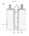
- FIG. 5 is a cross-sectional view of a secondary battery module a still further embodiment of the present invention.
- FIG. 6A is an exploded perspective view of a secondary battery module according to yet another embodiment of the present invention.
- FIG. 6B is a perspective view of a first barrier shown in FIG. 6A ;
- FIG. 6C is an enlarged view of an exemplary spacer shown in FIG. 6A ;
- FIG. 6D is a cross-sectional view of the secondary battery module shown in FIG. 6A .
- FIG. 1A is a perspective view of a secondary battery module according to one embodiment of the present invention
- FIG. 1B is an exploded perspective view of the secondary battery module shown in FIG. 1A
- FIG. 1C is a cross-sectional view of a unit battery shown in FIG. 1A
- FIG. 1D is a perspective view of a first barrier shown in FIG. 1A
- FIG. 1E is an enlarged view of a spacer shown in FIG. 1A
- FIG. 1F is a cross-sectional view of the secondary battery module taken along the line A-A′ of FIG. 1A .
- the secondary battery module 100 includes unit cells 110 , a first barrier 120 , a second barrier 130 , and spacers 140 .
- Each of the unit cells 110 includes an electrode assembly 114 having a positive electrode plate 111 , a negative electrode plate 112 , and a separator 113 between the positive electrode plate 111 and the negative electrode plate 112 , a case 115 having a space for accommodating the electrode assembly, a cap plate 116 coupled to the case 115 and sealing the same, and positive/negative terminals 117 and 118 electrically connected to the positive/negative electrode plates 111 and 112 , respectively, and protruding outwardly from the cap plate 116 .
- the positive electrode plate 111 is formed by coating a positive electrode active material such as a transition metal oxide on a positive electrode collector formed of a metal foil made of, for example, aluminum (Al), and includes a positive electrode non-coating portion 111 a that is not coated with the positive electrode active material.
- the positive electrode non-coating portion 111 a is formed on a lateral surface of the positive electrode plate 111 in a lengthwise direction of the positive electrode plate 111 .
- the positive electrode non-coating portion 111 a serves as a flow channel of current flowing between the positive electrode plate 111 and the positive terminal 117 .
- aspects of the present invention are not limited to the exemplary material of the positive electrode plate 111 .
- the negative electrode plate 112 is formed by coating a negative electrode active material such as graphite or carbon on a negative electrode collector formed of a metal foil made of, for example, nickel (Ni) or copper (Cu), includes a negative electrode non-coating portion 112 a that is not coated with the negative electrode active material.
- the negative electrode non-coating portion 112 a is formed on a lateral surface of the negative electrode plate 112 in a lengthwise direction of the negative electrode plate 112 .
- the negative electrode non-coating portion 112 a serves as a flow channel of current flowing between the negative electrode plate 112 and the negative terminal 118 .
- aspects of the present invention are not limited to the exemplary materials of the negative electrode plate 112 .
- the separator 113 positioned between the positive electrode plate 111 and the negative electrode plate 112 , prevents an electrical short-circuit therebetween and allows for movement of lithium ions.
- the separator 113 is made of polyethylene, polypropylene, and a composite film of polyethylene and polypropylene.
- aspects of the present invention are not limited to the exemplary materials of the separator 113 .
- the electrode assembly 114 may be formed by winding together the positive electrode plate 111 , the negative electrode plate 112 , and the separator 113 between the positive electrode plate 111 and the negative electrode plate 112 in a jelly-roll configuration, with the separator electrically insulating the positive electrode plate 111 and the negative electrode plate 112 from each other.
- the electrode assembly 114 may be flatly compressed to be encased in a case 115 of a prismatic shape by, for example, a pressing process.
- the case 115 is made of a conductive metal, such as Al, Al alloy, or Ni-coated steel, and is formed in a substantially hexahedral shape having an opening to receive the electrode assembly 114 , the positive terminal 117 , the negative terminal 118 , and electrolyte. While the opening is not shown in FIG. 1C , in which the case 115 and cap plate 116 are shown coupled, the edge portion of the cap plate 116 is actually an open portion. An inner surface of the case 115 is treated for insulation to be electrically insulated from the electrode assembly 114 , the positive terminal 117 and the negative terminal 118 .
- the cap plate 116 seals the opening of the case 115 , and may be made of the same material as the case 115 .
- the cap plate 116 may include a plug for closing an electrolyte inlet and a safety vent.
- the positive terminal 117 is electrically connected to the positive electrode plate 111 and protrudes outwardly from the cap plate 116 . That is, one end of the positive terminal 117 is welded to the positive electrode non-coating portion 111 a to be connected to the positive electrode plate 111 and the other end of the positive terminal 117 extends through the cap plate 116 to protrude outwardly from the cap plate 116 .
- the negative terminal 118 is electrically connected to the negative electrode plate 112 to protrude outwardly from the cap plate 116 . That is, one end of the negative terminal 118 is welded to the negative electrode non-coating portion 112 a to be connected to the negative electrode plate 112 and the other end of the negative terminal 118 extends through the cap plate 116 to then protrude outwardly from the cap plate 116 .
- the first barrier 120 is between adjacent unit cells 110 , and one surface of the first barrier 120 is combined with one surface of one of the adjacent unit cells 110 .
- the first barrier 120 may be sized to have an area substantially the same as or greater than the surface of the unit cell 110 to which it corresponds.
- the first barrier 120 may include a metal plate 120 a and an oxide layer 120 b formed on a surface of the metal plate 120 a .
- the metal plate 120 a is made of aluminum (Al), and has excellent thermal conductivity, thereby efficiently cooling the unit cells 110 .
- the oxide layer 120 b is a coating formed by anodizing the surface of the metal plate 120 a .
- the anodizing is performed such that a surface of an aluminum body used as a positive electrode is oxidized by the oxygen produced when the aluminum body is conducted in electrolyte to yield a coating of aluminum oxide (Al 2 O 3 ).
- the most typically used material in the anodizing treatment is aluminum (Al).
- the anodizing treatment may be performed on a metal body made of manganese (Mn), zinc (Zn), titanium (Ti), hafnium (Hf), niobium (Nb), or the like.
- the oxide layer 120 b has very high mechanical strength and superb corrosion resistance and abrasion resistance. That is, the first barrier 120 is made of aluminum having excellent thermal conductivity so that it can efficiently dissipate the heat generated from the unit cells 110 . In addition, the first barrier 120 can prevent or reduce the likelihood of an electrical short-circuit between the unit cells 110 due to the oxide layer 120 b on its surface.
- the first barrier 120 includes spacer holes 121 arranged at a predetermined distance, the spacer holes 121 corresponding to the spacers 140 .
- Each of the spacer holes 121 includes a protrusion hole 121 a and an insert hole 121 b corresponding respectively to a protrusion 142 of each of the spacers 140 and inserts 142 a formed on the protrusion 142 .
- the spacer 140 is fitted into the spacer hole 121 formed in the first barrier 120 .
- the insert 142 a is fitted into the insert hole 121 b , the spacer 140 can be securely fixed and substantially prevented from being moved or rotated.
- the second barrier 130 is between the unit cells 110 and spaced from the first barrier 120 .
- the second barrier 130 includes spacer holes 131 spaced from each other, the spacer holes 131 corresponding to the spacers 140 .
- the spacer holes 121 of the first barrier 120 correspond to the spacer holes 131 of the second barrier 130 .
- the second barrier 130 has substantially the same configuration and functions as the first barrier 120 , repetitive descriptions thereof will not be given.
- the spacers 140 are formed between the first barrier 120 and the second barrier 130 .
- Each of the spacers 140 includes a spacer body 141 and a protrusion 142 protruding from both planar surfaces of the spacer body 141 , the protrusion having a smaller area than an area of the spacer body 141 .
- the spacers 140 are fitted into the spacer holes 121 and 131 formed in the first barrier 120 and the second barrier 130 .
- the spacers 140 are formed of insulators and prevent or reduce a likelihood of an electrical short-circuit between the unit cells 110 .
- the spacers 140 may be made of plastic (polymer resin) or silicon, but aspects of the present invention are not limited thereto.
- the spacer body 141 is formed in a generally circular shape and has a predetermined thickness.
- the spacer body 141 has a circular shape, but is not limited thereto and may have one of various shapes, including a triangular shape, a rectangular shape, a pentagonal shape, and so on.
- the protrusion 142 protrudes from both planar surfaces of the spacer body 141 and, in one embodiment, a protruding distance of the protrusion 142 is less than a thickness of the spacer body 141 .
- inserts 142 a are positioned on the outer circumference of the protrusion 142 and are formed on both surfaces of the spacer body 141 .
- the inserts 142 a are formed on the spacer body 141 extending in a radial direction from the center to the exterior side of the protrusion 142 .
- the protrusion 142 is engaged with the protrusion hole 121 a and, more specifically, the protrusion 142 is fitted into the protrusion hole 121 a to be close contact with the unit cells 110 .
- the inserts 142 a are engaged with the insert holes 121 b , and more specifically, the inserts 142 a are inserted into the insert holes 121 b to be close contact with the unit cells 110 , thereby securely fixing the spacers 140 without being moved.
- the spacers 140 are combined with the first barrier 120 such that the protrusion 142 and the inserts 142 a are fitted and inserted respectively into the protrusion hole 121 a and the insert holes 121 b.
- the first barrier 120 is coupled to one surface of each of the unit cells 110 and the second barrier 130 is coupled to the other surface thereof.
- the spacers 140 are engaged with the spacer holes 121 and 131 formed in the first barrier 120 and the second barrier 130 . That is, the unit cells 110 are in surface-contact with the first and second barriers 120 and 130 , thereby preventing or reducing the likelihood that the unit cells will be damaged due to external impacts and vibration.
- cooling channels through which the heat generated from the unit cells 110 can be dissipated, are formed by locating the spacers 140 between the first barrier 120 and the second barrier 130 .
- the unit cells 110 are in surface-contact with the first and second barriers 120 and 130 , it is possible to prevent the unit cells 110 from being damaged due to external impact and vibration.
- the secondary battery module 100 includes cooling channels formed by locating the spacers 140 between the first barrier 120 and the second barrier 130 by an equal distance, thereby dissipating the heat generated from the unit cells 110 .
- FIG. 2 is an exploded perspective view of a secondary battery module according to another embodiment of the present invention.
- the secondary battery module 200 is substantially the same as the secondary battery module 100 shown in FIGS. 1A through 1F in view of configuration and functions, except for configurations of a first barrier 220 and a second barrier 230 .
- first barrier 220 and a second barrier 230 are substantially the same as the secondary battery module 100 shown in FIGS. 1A through 1F in view of configuration and functions, except for configurations of a first barrier 220 and a second barrier 230 .
- the first barrier 220 is located between the unit cells 110 , and one surface of the first barrier 220 is combined with one surface of each of the unit cells 110 .
- the first barrier 220 includes a plurality of spacer holes 221 corresponding to the spacers 140 arranged therein.
- a distance between the spacer holes 221 arranged at a central area of the first barrier 220 is smaller than a distance between spacer holes 221 arranged at a peripheral area thereof. That is, the spacer holes 221 are more densely located at the central area of the first barrier 220 .
- the spacers 140 are fitted into the spacer holes 221 formed in the first barrier 220 . Because the spacer holes 221 are more densely formed at the central area of the first barrier 220 as described above, the spacers 140 are also more densely formed at the central area of the first barrier 220 .
- the unit cells 110 typically undergo a swelling phenomenon, which may occur to a greater degree at central areas of the unit cells 110 .
- occurrence of the swelling phenomenon of the unit cells 110 can be minimized by more densely arranging the spacers 140 at the central area of the first barrier 220 .
- the second barrier 230 is substantially the same as the first barrier 220 in view of configuration and functions, repetitive explanations will be omitted.
- the unit cells 110 are in surface-contact with the first and second barriers 220 and 230 , it is possible to prevent or reduce the likelihood that the unit cells 110 will be damaged due to external impacts or vibration
- the secondary battery module 200 includes the spacers 140 more densely formed at the central areas of the first and second barriers 220 and 230 , occurrence of the swelling phenomenon of the unit cells 110 can be minimized.
- FIG. 3A is a perspective view of a first barrier of a secondary battery module according to still another embodiment of the present invention
- FIG. 3B is a cross-sectional view of the secondary battery module shown in FIG. 3A .
- the secondary battery module 300 is substantially the same as the secondary battery module 100 shown in FIGS. 1A through 1F in view of configuration and functions, except for configurations of a first barrier 320 and a second barrier 330 .
- first barrier 320 and a second barrier 330 are substantially the same as the secondary battery module 100 shown in FIGS. 1A through 1F in view of configuration and functions, except for configurations of a first barrier 320 and a second barrier 330 .
- the first barrier 320 is located between the unit cells 110 , and one surface of the first barrier 320 is combined with one surface of one of the unit cells 110 . In other words, a surface of the first barrier 320 is in contact with substantially an entire surface of the unit cell 110 .
- the first barrier 320 includes a plurality of spacer grooves 321 corresponding to the spacers 140 arranged therein at an equal distance.
- the spacer grooves 321 include a protrusion groove 321 a corresponding to a protrusion 142 , and insert grooves 321 b corresponding to inserts 142 a .
- the spacers 140 are fitted into the spacer grooves 321 formed in the first barrier 320 .
- the inserts 142 a are fitted into the insert grooves 321 b , the spacers 140 can be securely fixed without becoming dislodged.
- the second barrier 330 is located between the unit cells 110 and spaced from the first barrier 320 .
- the second barrier 330 includes spacer holes 331 arranged at an equal distance, the spacer holes 131 corresponding to the spacers 140 .
- the spacer grooves 321 of the first barrier 320 correspond to the spacer grooves 331 of the second barrier 330 .
- the second barrier 330 has substantially the same configuration and functions as the first barrier 320 , repetitive descriptions thereof will not be given.
- the unit cells 110 are in surface-contact with the first and second barriers 320 and 330 , it is possible to prevent or reduce the likelihood that the unit cells 110 will be damaged due to external impacts and vibration.
- the secondary battery module 300 includes the cooling channels formed by locating the spacers 140 between the first barrier 320 and the second barrier 330 at the same distance, thereby dissipating the heat generated from the unit cells 110 .
- FIG. 4A is an exploded perspective view of a secondary battery module according to a further embodiment of the present invention
- FIG. 4B is a perspective view of first and second barriers of the secondary battery module shown in FIG. 4A
- FIG. 4C is a perspective view of a spacer shown in FIG. 4A .
- the secondary battery module 400 is substantially the same as the secondary battery module 100 shown in FIGS. 1A through 1F in view of configuration and functions. Thus, repetitive explanations will be omitted and the following description will be focused on only the differences therebetween.
- the secondary battery module 400 includes unit cells 110 , a first barrier 420 , a second barrier 130 , and spacers 440 .
- the first barrier 420 is located between the unit cells 110 and is formed in a flat rectangular plate shape. One surface of the first barrier 420 is combined with one surface of the unit cell 110 , and the other surface of the first barrier 420 is combined with surfaces of the spacers 440 without the protrusion 442 .
- the second barrier 130 is located between the unit cells 110 and is spaced from the first barrier 420 .
- the second barrier 130 includes spacer holes 131 corresponding to the spacers 440 arranged at an equal distance.
- first barrier 420 and the second barrier 130 may be reversed.
- the spacers 440 are formed between the first barrier 420 and the second barrier 130 .
- Each of the spacers 440 includes a spacer body 441 , and a protrusion 442 protruding from one surface of the spacer body 441 and having a smaller area than an area of the spacer body 441 .
- the spacers 440 are fitted into the spacer holes 131 formed in the second barrier 130 .
- the spacers 440 are formed of insulators and prevent an electrical short-circuit between the unit cells 110 .
- the protrusion 442 protrudes from one surface of the spacer body 441 and protrudes a distance less than a thickness of the spacer body 441 .
- the inserts 442 a are positioned on the outer circumference of the protrusion 442 .
- the inserts 442 a are also formed on one surface of the spacer body 441 . That is, the spacers 440 are combined with the second barrier 130 such that the protrusion 442 and the inserts 442 a are fitted into the protrusion hole 131 a and the insert holes 131 b , respectively.
- the unit cells 110 are in surface-contact with the first and second barriers 420 and 130 , it is possible to prevent the unit cells 110 from being damaged due to external impact and vibration.
- the secondary battery module 400 includes the cooling channels formed by locating the spacers 440 between the first barrier 420 and the second barrier 130 at an equal distance, thereby dissipating the heat generated from the unit cells 110 .
- FIG. 5 is a cross-sectional view of a secondary battery module according to a still further embodiment of the present invention.
- the secondary battery module 500 is substantially the same as the secondary battery module 300 shown in FIG. 3B in view of configuration and functions. Thus, repetitive explanations will be omitted and the following description will be focused on only the differences therebetween.
- the secondary battery module 500 includes unit cells 110 , a first barrier 520 , a second barrier 330 and spacers 440 .
- the first barrier 520 is located between the unit cells 110 and is formed in a flat rectangular plate shape. One surface of the first barrier 520 is combined to cover substantially an entire surface of the unit cell 110 , and the other surface of the first barrier 520 is combined with surfaces of the spacers 440 without the protrusion 442 .
- the second barrier 330 is located between the unit cells 110 and is spaced from the first barrier 420 .
- the second barrier 330 covers substantially an entire surface of the unit cell 110 and includes spacer grooves 331 corresponding to the spacers 440 spaced at an equal distance.
- first barrier 520 and the second barrier 330 may be reversed.
- the spacers 440 are formed between the first barrier 520 and the second barrier 330 .
- Each of the spacers 440 includes a spacer body 441 , and a protrusion 442 protruding from one surface of the spacer body 441 in a smaller size than the spacer body 441 .
- the spacers 440 are fitted into the spacer grooves 331 formed in the second barrier 330 .
- the spacers 440 are formed of insulators and prevent an electrical short-circuit between the unit cells 110 .
- the unit cells 110 are in surface-contact with the first and second barriers 520 and 330 , allowing the barriers to prevent the unit cells 110 from being significantly damaged due to external impact and vibration.
- the secondary battery module 500 includes the cooling channels formed by locating the spacers 440 between the first barrier 520 and the second barrier 330 at substantially an equal distance, thereby dissipating the heat generated from the unit cells 110 .
- FIG. 6A is an exploded perspective view of a secondary battery module according to yet another embodiment of the present invention
- FIG. 6B is a perspective view of a first barrier shown in FIG. 6A
- FIG. 6C is an enlarged view of an exemplary spacer shown in FIG. 6A
- FIG. 6D is a cross-sectional view of the secondary battery module shown in FIG. 6A .
- the secondary battery module 600 includes unit cells 110 , a first barrier 620 , a second barrier 630 and spacers 640 .
- the first barrier 620 is located between the unit cells 110 and one surface of the first barrier 620 is combined with one surface of the unit cell 110 .
- the first barrier 620 may have an area that is the same as or smaller than an area of one surface of each of the unit cells 110 .
- a plurality of protrusions 622 outwardly protrude from one surface of the first barrier 620 .
- the plurality of protrusions 622 are engaged with protrusion holes 642 formed in the spacers 640 .
- Inserts 622 a are formed on outer circumferences of the protrusions 622 . Like the protrusions 622 , the inserts 622 a are formed on one surface of the first barrier 620 . That is, the inserts 622 a are formed on one surface of the first barrier 620 extending in a radial direction from the center to the exterior side of the protrusions 622 . The inserts 622 a are engaged with insert holes 642 a formed in the spacers 640 . Here, the inserts 622 a are inserted into the insert holes 642 a , thereby securely fixing the spacers 640 without being moved.
- the second barrier 630 is located between the unit cells 110 and is spaced from the first barrier 620 .
- the spacers 640 include protrusions 632 formed on one surface thereof, and the protrusions 632 may be in contact with the protrusions 622 of the first barrier 620 .
- the second barrier 630 has the same configuration and functions as the first barrier 320 , repetitive descriptions thereof will not be given.
- the spacers 640 are formed between the first barrier 620 and the second barrier 630 .
- Each of the spacers 640 includes the protrusion holes 642 corresponding to the protrusions 622 and insert holes 642 a corresponding to the inserts 622 a.
- the spacers 640 are engaged with the protrusions 622 and 632 formed in the first and second barriers 620 and 630 , respectively.
- a thickness of each of the spacers 640 may be equal to or greater than a sum of thicknesses of each of the protrusions 622 of the first barrier 620 and each of the protrusions 632 of the second barrier 630 .
- the thickness of the spacer 640 is substantially equal to the sum of thicknesses of the protrusion 622 of the first barrier 620 and the protrusion 632 of the second barrier 630 . If the thickness of the spacer 640 is greater than the sum of thicknesses of the protrusion 622 of the first barrier 620 and the protrusion 632 of the second barrier 630 , the protrusion 622 of the first barrier 620 and the protrusion 632 of the second barrier 630 may not come into contact with each other.
- the unit cells 110 are in surface-contact with the first and second barriers 620 and 630 , it is possible to prevent the unit cells 110 from being damaged due to external impacts and vibration.
- the secondary battery module 600 includes the cooling channels formed by interposing the spacers 640 between the first barrier 620 and the second barrier 630 at an equal distance, thereby dissipating the heat generated from the unit cells 110 .
Landscapes
- Chemical & Material Sciences (AREA)
- Chemical Kinetics & Catalysis (AREA)
- Electrochemistry (AREA)
- General Chemical & Material Sciences (AREA)
- Engineering & Computer Science (AREA)
- Manufacturing & Machinery (AREA)
- Battery Mounting, Suspending (AREA)
- Secondary Cells (AREA)
Abstract
Description
Claims (17)
Applications Claiming Priority (2)
| Application Number | Priority Date | Filing Date | Title |
|---|---|---|---|
| KR10-2010-0009201 | 2010-02-01 | ||
| KR1020100009201A KR101182958B1 (en) | 2010-02-01 | 2010-02-01 | Secondary battery module |
Publications (2)
| Publication Number | Publication Date |
|---|---|
| US20110189531A1 US20110189531A1 (en) | 2011-08-04 |
| US8765285B2 true US8765285B2 (en) | 2014-07-01 |
Family
ID=42712543
Family Applications (1)
| Application Number | Title | Priority Date | Filing Date |
|---|---|---|---|
| US12/815,587 Active 2031-05-26 US8765285B2 (en) | 2010-02-01 | 2010-06-15 | Secondary battery module |
Country Status (5)
| Country | Link |
|---|---|
| US (1) | US8765285B2 (en) |
| EP (1) | EP2355231B8 (en) |
| JP (1) | JP5186700B2 (en) |
| KR (1) | KR101182958B1 (en) |
| CN (1) | CN102142527B (en) |
Cited By (4)
| Publication number | Priority date | Publication date | Assignee | Title |
|---|---|---|---|---|
| USD782409S1 (en) * | 2015-03-30 | 2017-03-28 | Johnson Controls Technology Company | Lithium ion battery cell with terminal washers |
| US20170237112A1 (en) * | 2016-01-21 | 2017-08-17 | 24M Technologies, Inc. | Porous spacers for electrochemical cells |
| US9911951B2 (en) | 2014-09-30 | 2018-03-06 | Johnson Controls Technology Company | Battery module compressed cell assembly |
| US11349178B2 (en) | 2018-07-25 | 2022-05-31 | Samsung Sdi Co., Ltd. | Battery pack with sealed air gap between cells |
Families Citing this family (17)
| Publication number | Priority date | Publication date | Assignee | Title |
|---|---|---|---|---|
| DE102013201729A1 (en) * | 2013-02-04 | 2014-08-07 | Robert Bosch Gmbh | Battery cell with positioning projection, module housing with positioning receiver, battery module with battery cell and module housing as well as battery with battery module and motor vehicle with battery |
| US10084218B2 (en) * | 2014-05-09 | 2018-09-25 | Lg Chem, Ltd. | Battery pack and method of assembling the battery pack |
| KR102378426B1 (en) * | 2014-07-28 | 2022-03-24 | 삼성에스디아이 주식회사 | Battery module |
| CN106784510B (en) * | 2017-03-15 | 2019-04-16 | 安徽江淮汽车集团股份有限公司 | Battery fixed mechanism, battery mould group assembly and automobile |
| JP6988346B2 (en) * | 2017-10-03 | 2022-01-05 | トヨタ自動車株式会社 | Power storage device |
| KR102467539B1 (en) * | 2018-05-02 | 2022-11-14 | 주식회사 엘지에너지솔루션 | Battery module |
| DE102018216720A1 (en) * | 2018-09-28 | 2020-04-02 | Robert Bosch Gmbh | Cooling plate for tempering at least one battery cell and battery system |
| JP7074019B2 (en) * | 2018-10-24 | 2022-05-24 | トヨタ自動車株式会社 | Power storage device |
| WO2020158430A1 (en) * | 2019-01-30 | 2020-08-06 | 株式会社Gsユアサ | Power storage device |
| KR102914405B1 (en) * | 2019-12-17 | 2026-01-19 | 삼성에스디아이 주식회사 | Battery Module |
| JP7631866B2 (en) * | 2020-06-29 | 2025-02-19 | トヨタ自動車株式会社 | Battery pack |
| KR20230068786A (en) * | 2021-11-11 | 2023-05-18 | 삼성에스디아이 주식회사 | Rechargeable battery module |
| WO2023089770A1 (en) * | 2021-11-19 | 2023-05-25 | 株式会社フコク | Elastic body for battery module |
| DE102022128913B3 (en) * | 2022-11-02 | 2024-02-01 | Dr. Ing. H.C. F. Porsche Aktiengesellschaft | Device for cooling a battery, method for producing the device, battery and vehicle comprising the device |
| WO2024144085A1 (en) * | 2022-12-26 | 2024-07-04 | 주식회사 엘지에너지솔루션 | Cell module assembly and battery pack including same |
| KR20240123671A (en) * | 2023-02-07 | 2024-08-14 | 주식회사 엘지에너지솔루션 | Cell stack assembly and battery pack including the same |
| FR3149433A1 (en) * | 2023-05-30 | 2024-12-06 | Psa Automobiles Sa | BATTERY PACK COMPRISING BATTERY CELLS SEPARATED BY SPACERS COMPRISING A LOWER PARTITION, VEHICLE AND METHOD BASED ON SUCH A BATTERY PACK |
Citations (10)
| Publication number | Priority date | Publication date | Assignee | Title |
|---|---|---|---|---|
| US3206170A (en) * | 1959-10-13 | 1965-09-14 | American Enka Corp | Mixing apparatus |
| WO1994002969A1 (en) | 1992-07-27 | 1994-02-03 | Bertin & Cie | Electrical accumulator battery with a cooling system, and assembly comprising same |
| US5800942A (en) | 1995-10-24 | 1998-09-01 | Matsushita Electric Industrial Co., Ltd. | Storage battery with ventilation system |
| JP2000048867A (en) | 1998-07-31 | 2000-02-18 | Toyota Motor Corp | Battery pack |
| JP2003323871A (en) | 2002-04-30 | 2003-11-14 | Japan Storage Battery Co Ltd | Battery pack |
| US20050287426A1 (en) * | 2004-06-25 | 2005-12-29 | Kim Tae-Yong | Secondary battery module |
| CN2770102Y (en) | 2005-01-07 | 2006-04-05 | 深圳富泰宏精密工业有限公司 | Battery cover clamping structure |
| US20070178377A1 (en) * | 2006-02-02 | 2007-08-02 | Samsung Sdi Co., Ltd. | Cell barrier for secondary battery module and secondary battery module |
| JP2008108651A (en) | 2006-10-27 | 2008-05-08 | Toyota Motor Corp | Battery pack and manufacturing method thereof |
| US20080248377A1 (en) * | 2004-10-22 | 2008-10-09 | Nissan Motor Co., Ltd. | Battery Module and Battery Assembly |
Family Cites Families (2)
| Publication number | Priority date | Publication date | Assignee | Title |
|---|---|---|---|---|
| KR100582558B1 (en) * | 2004-11-25 | 2006-05-22 | 한국전자통신연구원 | Lithium metal cathode for lithium metal polymer secondary battery with spacer and manufacturing method thereof |
| KR100669424B1 (en) * | 2005-03-11 | 2007-01-15 | 삼성에스디아이 주식회사 | Battery Modules and Battery Modules |
-
2010
- 2010-02-01 KR KR1020100009201A patent/KR101182958B1/en active Active
- 2010-06-10 JP JP2010133209A patent/JP5186700B2/en active Active
- 2010-06-15 US US12/815,587 patent/US8765285B2/en active Active
- 2010-07-23 EP EP20100170554 patent/EP2355231B8/en active Active
- 2010-12-21 CN CN2010106087068A patent/CN102142527B/en active Active
Patent Citations (13)
| Publication number | Priority date | Publication date | Assignee | Title |
|---|---|---|---|---|
| US3206170A (en) * | 1959-10-13 | 1965-09-14 | American Enka Corp | Mixing apparatus |
| WO1994002969A1 (en) | 1992-07-27 | 1994-02-03 | Bertin & Cie | Electrical accumulator battery with a cooling system, and assembly comprising same |
| US5800942A (en) | 1995-10-24 | 1998-09-01 | Matsushita Electric Industrial Co., Ltd. | Storage battery with ventilation system |
| JP2000048867A (en) | 1998-07-31 | 2000-02-18 | Toyota Motor Corp | Battery pack |
| JP2003323871A (en) | 2002-04-30 | 2003-11-14 | Japan Storage Battery Co Ltd | Battery pack |
| JP2006012847A (en) | 2004-06-25 | 2006-01-12 | Samsung Sdi Co Ltd | Secondary battery module |
| US20050287426A1 (en) * | 2004-06-25 | 2005-12-29 | Kim Tae-Yong | Secondary battery module |
| US20080248377A1 (en) * | 2004-10-22 | 2008-10-09 | Nissan Motor Co., Ltd. | Battery Module and Battery Assembly |
| CN2770102Y (en) | 2005-01-07 | 2006-04-05 | 深圳富泰宏精密工业有限公司 | Battery cover clamping structure |
| US20060154136A1 (en) * | 2005-01-07 | 2006-07-13 | Fih Co.,Ltd | Battery cover latching assembly for portable electronic device |
| US20070178377A1 (en) * | 2006-02-02 | 2007-08-02 | Samsung Sdi Co., Ltd. | Cell barrier for secondary battery module and secondary battery module |
| CN101013748A (en) | 2006-02-02 | 2007-08-08 | 三星Sdi株式会社 | A cell barrier for a rechargeable battery module and rechargeable battery module |
| JP2008108651A (en) | 2006-10-27 | 2008-05-08 | Toyota Motor Corp | Battery pack and manufacturing method thereof |
Non-Patent Citations (9)
| Title |
|---|
| English Machine Translation of Japanese Publication JP2000-048867 listed above. |
| European Office Action dated Apr. 14, 2011 issued to corresponding application EP 10-170-554.9-2119, listing the cited reference in this IDS, 4 pages. |
| Extended European Search Report dated Oct. 4, 2010 issued by the EPO for the Priority Korean Patent Application No. 10170554.9, 6 pages. |
| First Office Action (with English translation) dated Mar. 28, 2013 issued in the Chinese Patent Application No. 201010608706.8, 23 pages. |
| Machine English Translation of JP2000-048867, Patent Abstracts of Japan, 6 pages. |
| Machine Translation of Kim (KR 10-2007-0025736, published Mar. 2007, pp. 1-18). * |
| Machine Translation of Kim et al. (JP 2006-012847, published Jan. 2006, pp. 1-25). * |
| Patent Abstracts of Japan, and English machine translation of Japanese Publication 2003-323871 listed above, (7 pages). |
| Patent Abstracts of Japan, and English machine translation of Japanese Publication 2008-108651 listed above, (19 pages). |
Cited By (6)
| Publication number | Priority date | Publication date | Assignee | Title |
|---|---|---|---|---|
| US9911951B2 (en) | 2014-09-30 | 2018-03-06 | Johnson Controls Technology Company | Battery module compressed cell assembly |
| US10665833B2 (en) | 2014-09-30 | 2020-05-26 | Cps Technology Holdings Llc | Battery module compressed cell assembly |
| US11462795B2 (en) | 2014-09-30 | 2022-10-04 | Cps Technology Holdings Llc | Battery module having a cell assembly |
| USD782409S1 (en) * | 2015-03-30 | 2017-03-28 | Johnson Controls Technology Company | Lithium ion battery cell with terminal washers |
| US20170237112A1 (en) * | 2016-01-21 | 2017-08-17 | 24M Technologies, Inc. | Porous spacers for electrochemical cells |
| US11349178B2 (en) | 2018-07-25 | 2022-05-31 | Samsung Sdi Co., Ltd. | Battery pack with sealed air gap between cells |
Also Published As
| Publication number | Publication date |
|---|---|
| KR20110089694A (en) | 2011-08-09 |
| US20110189531A1 (en) | 2011-08-04 |
| CN102142527B (en) | 2013-11-20 |
| JP5186700B2 (en) | 2013-04-17 |
| KR101182958B1 (en) | 2012-09-18 |
| EP2355231B1 (en) | 2013-02-20 |
| CN102142527A (en) | 2011-08-03 |
| EP2355231B8 (en) | 2013-04-17 |
| JP2011159617A (en) | 2011-08-18 |
| EP2355231A1 (en) | 2011-08-10 |
Similar Documents
| Publication | Publication Date | Title |
|---|---|---|
| US8765285B2 (en) | Secondary battery module | |
| US10446812B2 (en) | Battery pack and manufacturing method therefor | |
| US10062871B2 (en) | Rechargeable battery with tabs | |
| US8450006B2 (en) | Rechargeable battery | |
| US10297801B2 (en) | Battery pack and manufacturing method therefor | |
| US7655353B2 (en) | Battery | |
| EP4350848B1 (en) | Venting device | |
| CN102356496B (en) | Secondary battery | |
| US10840498B2 (en) | Secondary battery | |
| US20230216134A1 (en) | Secondary battery | |
| US8592082B2 (en) | Electrode assembly and secondary battery having the same | |
| US9324987B2 (en) | Secondary battery | |
| US9818991B2 (en) | Secondary battery | |
| US20080226981A1 (en) | Center pin cylindrical secondary battery and cylindrical secondary battery having the same | |
| US9147878B2 (en) | Secondary battery comprising at least a first and second electrode each coated with an active material layer | |
| US8481193B2 (en) | Battery module and method of manufacturing the same | |
| US20060204842A1 (en) | Rechargeable battery and method of assembling for the same | |
| EP4207440B1 (en) | Secondary battery and a method of manufacturing a secondary battery | |
| US20250349999A1 (en) | Integrated terminal, secondary battery including the same, and method of manufacturing the same | |
| US20260106358A1 (en) | Cap assembly and secondary battery including same | |
| KR100670452B1 (en) | Electrode assembly and secondary battery using same | |
| KR20080037863A (en) | Cylindrical secondary battery | |
| KR20250154700A (en) | Secondary battery |
Legal Events
| Date | Code | Title | Description |
|---|---|---|---|
| AS | Assignment |
Owner name: SB LIMOTIVE CO., LTD., KOREA, REPUBLIC OF Free format text: ASSIGNMENT OF ASSIGNORS INTEREST;ASSIGNOR:KIM, MYUNGCHUL;REEL/FRAME:024546/0293 Effective date: 20100609 |
|
| AS | Assignment |
Owner name: ROBERT BOSCH GMBH, GERMANY Free format text: ASSIGNMENT OF ASSIGNORS INTEREST;ASSIGNOR:SB LIMOTIVE CO., LTD.;REEL/FRAME:029548/0033 Effective date: 20121204 Owner name: SAMSUNG SDI CO., LTD., KOREA, REPUBLIC OF Free format text: ASSIGNMENT OF ASSIGNORS INTEREST;ASSIGNOR:SB LIMOTIVE CO., LTD.;REEL/FRAME:029548/0033 Effective date: 20121204 |
|
| FEPP | Fee payment procedure |
Free format text: PAYOR NUMBER ASSIGNED (ORIGINAL EVENT CODE: ASPN); ENTITY STATUS OF PATENT OWNER: LARGE ENTITY |
|
| STCF | Information on status: patent grant |
Free format text: PATENTED CASE |
|
| MAFP | Maintenance fee payment |
Free format text: PAYMENT OF MAINTENANCE FEE, 4TH YEAR, LARGE ENTITY (ORIGINAL EVENT CODE: M1551) Year of fee payment: 4 |
|
| MAFP | Maintenance fee payment |
Free format text: PAYMENT OF MAINTENANCE FEE, 8TH YEAR, LARGE ENTITY (ORIGINAL EVENT CODE: M1552); ENTITY STATUS OF PATENT OWNER: LARGE ENTITY Year of fee payment: 8 |
|
| MAFP | Maintenance fee payment |
Free format text: PAYMENT OF MAINTENANCE FEE, 12TH YEAR, LARGE ENTITY (ORIGINAL EVENT CODE: M1553); ENTITY STATUS OF PATENT OWNER: LARGE ENTITY Year of fee payment: 12 |