US8760658B2 - Flow cell modules and liquid sample analyzers and methods including same - Google Patents
Flow cell modules and liquid sample analyzers and methods including same Download PDFInfo
- Publication number
- US8760658B2 US8760658B2 US13/781,025 US201313781025A US8760658B2 US 8760658 B2 US8760658 B2 US 8760658B2 US 201313781025 A US201313781025 A US 201313781025A US 8760658 B2 US8760658 B2 US 8760658B2
- Authority
- US
- United States
- Prior art keywords
- axis
- termination
- flow cell
- input
- liquid sample
- Prior art date
- Legal status (The legal status is an assumption and is not a legal conclusion. Google has not performed a legal analysis and makes no representation as to the accuracy of the status listed.)
- Expired - Fee Related
Links
Images




Classifications
-
- G—PHYSICS
- G01—MEASURING; TESTING
- G01N—INVESTIGATING OR ANALYSING MATERIALS BY DETERMINING THEIR CHEMICAL OR PHYSICAL PROPERTIES
- G01N21/00—Investigating or analysing materials by the use of optical means, i.e. using sub-millimetre waves, infrared, visible or ultraviolet light
- G01N21/01—Arrangements or apparatus for facilitating the optical investigation
- G01N21/03—Cuvette constructions
- G01N21/05—Flow-through cuvettes
-
- G—PHYSICS
- G01—MEASURING; TESTING
- G01N—INVESTIGATING OR ANALYSING MATERIALS BY DETERMINING THEIR CHEMICAL OR PHYSICAL PROPERTIES
- G01N21/00—Investigating or analysing materials by the use of optical means, i.e. using sub-millimetre waves, infrared, visible or ultraviolet light
- G01N21/17—Systems in which incident light is modified in accordance with the properties of the material investigated
- G01N21/59—Transmissivity
-
- G—PHYSICS
- G01—MEASURING; TESTING
- G01N—INVESTIGATING OR ANALYSING MATERIALS BY DETERMINING THEIR CHEMICAL OR PHYSICAL PROPERTIES
- G01N21/00—Investigating or analysing materials by the use of optical means, i.e. using sub-millimetre waves, infrared, visible or ultraviolet light
- G01N21/01—Arrangements or apparatus for facilitating the optical investigation
- G01N21/03—Cuvette constructions
- G01N21/05—Flow-through cuvettes
- G01N2021/052—Tubular type; cavity type; multireflective
Definitions
- the present technology relates to liquid sample analyzers and flow cell modules therefor.
- Liquid sample analyzers of known design include a flow cell, a light source for providing light to the flow cell, a liquid sample source for flowing a liquid sample through the flow cell, and a detector (e.g., a spectrometer) for receiving light from the flow cell (i.e., the light from the light source as modified by transmission through the flow of the liquid sample in the flow cell). It may be necessary or desirable to remove a given flow cell from the system (i.e., from between the light source and the detector) and reinstall the flow cell or replace it with a new flow cell. For this purpose, it is known to package a flow cell in a flow cell module that can be inserted between and removed from the system.
- a flow cell module for use in a liquid sample analyzer, the liquid sample analyzer including a radiation source, a sensing device, and a liquid sample source, includes a module housing, a liquid core waveguide, an input optical fiber, an input termination, and first and second kinematic connection mechanisms.
- the liquid core waveguide is mounted in the module housing and is configured to receive a flow of a liquid sample from the liquid sample source.
- the input optical fiber is disposed in the module housing and is configured to transmit radiation from the radiation source to the liquid core waveguide.
- the input termination is located on an input end of the input optical fiber.
- the first kinematic connection mechanism is operative to bias the input termination in a first direction along a first axis while permitting displacement of the input termination in a first opposing direction along the first axis.
- the second kinematic connection mechanism is operative to bias the input termination in a second direction along a second axis while permitting displacement of the input termination in a second opposing direction along the second axis.
- the second axis is transverse to the first axis.
- the first and second axes are substantially perpendicular.
- the first kinematic connection mechanism includes a first spring biasing the input termination in the first direction
- the second kinematic connection mechanism includes a second spring biasing the input termination in the second direction.
- the first spring is a coil spring and the second spring is a leaf spring.
- the input optical fiber is flexible.
- the flow cell module may further include: an output optical fiber disposed in the module housing and configured to transmit radiation from the liquid core waveguide to the sensing device; and an output termination on an output end of the output optical fiber, wherein the output termination is kinematically mounted in the module housing.
- the flow cell module may include a third kinematic connection mechanism operative to bias the output termination in a third direction along a third axis while permitting displacement of the output termination in a third opposing direction along the third axis.
- the third kinematic connection mechanism includes a third spring biasing the output termination in the third direction.
- a flow cell module for use in a liquid sample analyzer, the liquid sample analyzer including a radiation source, a sensing device and a liquid sample source, includes a module housing, a liquid core waveguide, an output optical fiber, and an output termination.
- the liquid core waveguide is mounted in the module housing and is configured to receive a flow of a liquid sample from the liquid sample source.
- the output optical fiber is disposed in the module housing and is configured to transmit radiation from the liquid core waveguide to the sensing device.
- the output termination is located on an output end of the output optical fiber. The output termination is kinematically mounted in the module housing.
- the flow cell module may include a kinematic connection mechanism operative to bias the output termination in a prescribed direction along a displacement axis while permitting displacement of the output termination in an opposing direction along the displacement axis.
- the kinematic connection mechanism includes a spring biasing the output termination in the prescribed direction.
- the output optical fiber is flexible.
- a flow cell module for use in a liquid sample analyzer, the liquid sample analyzer including a radiation source, a sensing device and a liquid sample source, includes a module housing, a liquid core waveguide, a flexible input optical fiber, an input termination, a flexible output optical fiber, and an output termination.
- the liquid core waveguide is mounted in the module housing and is configured to receive a flow of a liquid sample from the liquid sample source.
- the input optical fiber is disposed in the module housing and is configured to transmit radiation from the radiation source to the liquid core waveguide.
- the input termination is located on an input end of the input optical fiber.
- the flexible output optical fiber is disposed in the module housing and is configured to transmit radiation from the liquid core waveguide to the sensing device.
- the output termination is located on an output end of the output optical fiber.
- the input termination and the output termination are each mounted in the module housing.
- a liquid sample analyzer has a holding slot and includes a radiation source, a sensing device, a liquid sample source, an alignment structure associated with the radiation source, and a flow cell module configured to be mounted in the holding slot.
- the flow cell module includes: a module housing; a liquid core waveguide mounted in the module housing and configured to receive a flow of a liquid sample from the liquid sample source; an input optical fiber disposed in the module housing and configured to transmit radiation from the radiation source to the liquid core waveguide; an input termination on an input end of the input optical fiber; a first kinematic connection mechanism operative to bias the input termination in a first direction along a first axis while permitting displacement of the input termination in a first opposing direction along the first axis; and a second kinematic connection mechanism operative to bias the input termination in a second direction along a second axis while permitting displacement of the input termination in a second opposing direction along the second axis.
- the second axis is transverse to the first axis.
- the first kinematic connection mechanism and the second kinematic connection mechanism cooperate to automatically align the input termination with the alignment structure when the flow cell module is inserted into the holding slot to thereby properly position the input termination with respect to the radiation source.
- the alignment structure includes an alignment block adjacent the radiation source.
- the alignment block has a sidewardly open groove defined therein and configured to receive the input termination.
- the groove has a lengthwise groove axis.
- the flow cell module further includes an output optical fiber and an output termination.
- the output optical fiber is disposed in the module housing and is configured to transmit radiation from the liquid core waveguide to the sensing device.
- the output termination is located on an output end of the output optical fiber.
- the output termination is kinematically mounted in the module housing to facilitate alignment between the output termination and the sensing device when the flow cell module is inserted into the holding slot.
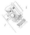
- FIG. 1 is a front perspective view of a liquid sample analyzer including a flow cell module according to embodiments of the technology.
- FIG. 2 is an exploded, front perspective view of the liquid sample analyzer of FIG. 1 .
- FIG. 3 is a perspective view of a subassembly forming a part of the liquid sample analyzer of FIG. 1 .
- FIG. 4 is a fragmentary, perspective view of the subassembly of FIG. 3 .
- FIG. 5 is a further fragmentary, perspective view of the subassembly of FIG. 3 .
- FIG. 6 is a further fragmentary, perspective view of the subassembly of FIG. 3 .
- FIG. 7 is a perspective view of a light source forming a part of the liquid sample analyzer of FIG. 1 .
- FIG. 8 is a rear perspective view of the flow cell module.
- FIG. 9 is a fragmentary, top, front perspective view of the flow cell module.
- FIG. 10 is an enlarged, fragmentary, top, front perspective yew of the flow cell module.
- FIG. 11 is a further enlarged, fragmentary, top, front perspective view of the flow cell module.
- FIG. 12 is an exploded, perspective view of a flow cell assembly forming a part of the flow cell module.
- FIG. 13 is a cross-sectional view of the flow cell assembly.
- FIG. 14 is a further cross-sectional view of the flow cell assembly.
- first, second, etc. may be used herein to describe various elements, components, regions, layers and/or sections, these elements, components, regions, layers and/or sections should not be limited by these terms. These terms are only used to distinguish one element, component, region, layer or section from another region, layer or section. Thus, a first element, component, region, layer or section discussed below could be termed a second element, component, region, layer or section without departing from the teachings of the present technology.
- spatially relative terms such as “beneath”, “below”, “lower”, “above”, “upper” and the like, may be used herein for ease of description to describe one element or feature's relationship to another element(s) or feature(s) as illustrated in the figures. It will be understood that the spatially relative terms are intended to encompass different orientations of the device in use or operation in addition to the orientation depicted in the figures. For example, if the device in the figures is turned over, elements described as “below” or “beneath” other elements or features would then be oriented “above” the other elements or features. Thus, the exemplary term “below” can encompass both an orientation of above and below. The device may be otherwise oriented (rotated 90° or at other orientations) and the spatially relative descriptors used herein interpreted accordingly.
- kinematically mounted means the subject component is mounted on or coupled to another component so as to provide or permit relative movement between the two components.
- Embodiments of the present technology are directed to flow cell modules and liquid sample analyzers incorporating the same.
- Flow cell modules as disclosed herein can be used in photometric apparatus for spectroscopic analysis, such as high performance chromatography (HPLC), capillary LC, and capillary electrophoresis (CE).
- HPLC high performance chromatography
- CE capillary electrophoresis
- the flow cell module includes a flow cell assembly mounted or packaged in a module housing or casing to facilitate ease of use and handling.
- the flow cell assembly provides a flow through liquid waveguide having a waveguide bore through which a stream of a liquid sample is flowed.
- the flow cell assembly provides fluidics for introducing the liquid sample into and removing the liquid sample from the waveguide bore.
- the flow cell assembly also provides a source optical fiber to guide radiation (e.g., UV or visible light) from a radiation source to the waveguide and a detector optical fiber to guide the radiation from the waveguide to a sensing device.
- radiation e.g., UV or visible light
- the light from the light source optical fiber is guided from the source optical fiber to the detector optical fiber through the waveguide and the liquid sample flowing therethrough by total internal reflection at the boundary between the liquid sample and the waveguide bore, for example.
- Ends of the optical fiber and the detector optical fiber are kinematically mounted in the housing of the flow cell module to enable convenient and effective connections between the fiber ends, the light source and the detector.
- a liquid sample analyzer 10 including a flow cell module 100 is shown therein.
- the liquid sample analyzer 10 further includes a remote radiation or light source 20 , a remote sensing device or detector 30 , and a carrier tray 60 affixed to a shared base 12 , and also a remote liquid sample source 50 ( FIG. 3 ) and a remote liquid sample receiver 52 .
- Some or all of these components may be housed in a cabinet 16 ( FIG. 1 ), for example.
- the light source 20 can be any suitable source of radiation or light for spectroscopic analysis.
- the light source 20 includes a housing 22 and an alignment device, structure or block 28 .
- a lamp 24 is contained in the housing 22 .
- the lamp 24 is a deuterium lamp.
- the alignment block 28 includes a V-shaped groove 28 A defining a lengthwise axis A-A, and a lateral or sideward opening 28 B.
- An opening or window 22 A is provided in the housing 22 . Light from the lamp 24 is emitted out of the housing 22 through the window 22 A, which may include a lens.
- the window 22 A can be aligned with the groove 28 A.
- the sensing device 30 may be any suitable sensing device or detector for spectroscopic analysis.
- the detector 30 is a spectrometer including a photodiode array (PDA).
- PDA photodiode array
- the detector 30 includes a fiber optic connector 32 for input of optical energy or signals for further processing.
- the liquid sample source 50 may be any suitable source including a supply of the sample to be analyzed in a liquid solvent. According to some embodiments, the solvent is aqueous.
- the liquid sample receiver 52 may be a waste receptacle or a down line process. According to some embodiments, at least one of the liquid sample source 50 and the liquid sample receiver 52 is provided with a pump to generate a forced flow of the liquid sample through the flow cell module 100 .
- the carrier tray 60 ( FIGS. 2 and 3 ) is secured to the base 12 and defines a holding cavity, socket or slot 64 and a front opening 62 communicating with the slot 64 .
- the tray 60 has track rails 66 and a latch (not shown).
- the flow cell module 100 includes a flow cell unit or assembly 110 , a connectorized radiation input or source optical fiber 120 , a connectorized radiation output or detector optical fiber 130 , a liquid sample feed capillary tube 140 , a liquid sample exit capillary tube 142 , a module housing 150 , an input connector axial biasing mechanism 170 (according to some embodiments and as shown, a coil spring), an input connector lateral biasing mechanism 172 (according to some embodiments and as shown, a leaf spring), an output connector biasing mechanism 174 (according to some embodiments and as shown, a coil spring), a liquid sample feed connector 176 , and a liquid sample exit connector 178 .
- the components 110 , 120 , 130 , 140 , 142 , 170 , 172 , 174 , 176 , and 178 are mounted in the module housing 150 , as discussed in more detail herein.
- the source connectorized fiber 120 includes a flexible optical fiber or waveguide 122 , a ferrule 124 , and a termination 126 .
- the optical fiber 122 may be an optical fiber including a solid glass core and a solid glass cladding and may be covered in a protective jacket 123 .
- the ferrule 124 is mounted on one end of the optical fiber 122 such that an output end face 122 A is exposed adjacent and substantially flush with an end face of the ferrule 124 .
- the termination 126 is mounted on the opposite end of the optical fiber 122 such that an input end face 122 B of the optical fiber 122 is exposed. In use, the termination 126 is installed proximate the light source 20 such that light from the light source 20 is directed into the optical fiber 122 through the end face 122 B and transmitted through the fiber 122 and out of the fiber 122 through the end face 122 A.
- the termination 126 includes a ferrule or shaft 126 A and a pair of axially spaced apart flanges 126 B extending radially outwardly from the shaft 126 A and defining a slot 126 C therebetween.
- a bore 126 D ( FIG. 6 ) extends through the shaft 126 A and the fiber 122 extends through the bore 126 D so that the fiber end face 122 B is located at or proximate the terminal end of the termination 126 .
- the termination 126 has a lengthwise axis G-G ( FIG. 12 ) intersecting the end face 122 B.
- the detector connectorized fiber 130 includes a flexible optical fiber 132 (which may be covered in a protective jacket 133 ), a ferrule 134 , and a termination 136 .
- the ferrule 134 is mounted on an end of the optical fiber 132 such that an input end face 132 A is exposed adjacent and substantially flush with an input end face of the ferrule 134 .
- the termination 136 is mounted on the opposite end of the fiber 132 such that an output end face 132 B of the fiber 132 is exposed. In use, the termination 136 is mated with the fiber optic connector 32 of the detector 30 to transmit light from the end face 132 A to the detector 30 .
- the termination 136 includes a ferrule or shaft 136 A and a pair of axially spaced apart flanges 136 B extending radially outwardly from the shaft 136 A and defining a slot 136 C therebetween.
- a bore 136 D extends through the shaft 136 A and the fiber 132 extends through the bore 136 D so that the fiber end face 132 B is located at or proximate the terminal end of the termination 136 .
- the termination 136 has a lengthwise axis H-H ( FIG. 12 ) intersecting the end face 132 A.
- the capillary tubes 140 , 142 fluidly couple the flow cell assembly 110 to the liquid sample source 50 and the liquid sample receiver 52 , respectively, via the connectors 176 , 178 .
- the capillary tubes 140 , 142 are flexible.
- the tubes 140 , 142 are formed of fused silica or quartz. The tubes 140 , 142 are terminated at the fluid connectors 176 , 178 to which the liquid sample source 50 and the liquid sample receiver 52 are fluidly coupled.
- the flow cell assembly 110 includes a flow cell or liquid core waveguide 112 mounted in or between an entrance “T” member or joint member 114 and an exit “T” member or joint member 116 , which are in turn mounted in a housing 118 .
- the waveguide 112 may include a waveguide body 115 and a cladding layer 111 extending through the waveguide body 115 .
- the cladding layer 111 is tubular and continuous and its outer surface is in intimate contact with the inner surface of the waveguide body 115 .
- the layer 111 is bonded to or forms a tight interference fit with the inner surface of the waveguide body 115 .
- the inner surface of the cladding layer 111 defines a passage or bore 111 A extending axially fully through the waveguide body 115 and terminating at opposed end openings 111 B, 111 C.
- the waveguide body 115 and the cladding layer 111 may be formed of any suitable materials.
- the waveguide body 115 is formed of a polymeric material.
- the waveguide body 115 is formed of polyetheretherketone (PEEK).
- the cladding layer 111 maybe formed of a material having a lower refractive index than that of the liquid sample.
- the cladding layer 111 is formed of a fluoropolymer and, in some embodiments, an amorphous fluoropolymer.
- the cladding layer 11 is formed of an amorphous copolymer of perfluora-2,2-dimethyl-1,3-dioxole and tetrafluoroethylene, an example of which is sold by E.I. du Pont de Nemours (commonly referred to as DuPont) under the trademark Teflon AF 2400TM.
- the cladding layer 111 has a thickness in the range of from about 0.005 to 0.010 inch and, in some embodiments, from about 0.010 to 0.020 inch.
- the cladding layer 111 is substantially free of any internal microbends or kinks.
- the flow cell assembly 110 includes a fluid feed port 117 A fluidly connecting the feed tube 140 to the end opening 111 B of the waveguide bore 111 A and a fluid exit port 117 B fluidly connecting the exit tube 142 to the end opening 111 C of the waveguide bore 111 A.
- the flow cell 110 also includes a source fiber receiving bore 117 C that receives the ferrule 126 and positions the fiber output end face 122 A adjacent the end opening 111 B, and a detector fiber receiving bore 117 D that receives the ferrule 134 and positions the fiber end face 132 A adjacent the end opening 111 C.
- the flow cell module housing 150 includes two subhousings 152 , 154 collectively defining a chamber 151 , an input leg 156 , an output leg 158 , and a flow cell holding leg 159 .
- the input leg 156 terminates at an input end 155 .
- the output leg 158 terminates at an output end 157 .
- Axially facing end connection openings 155 A and 157 A are defined in the ends 155 and 157 , respectively.
- a laterally or sidewardly facing side connection opening 155 B is defined in the input end 155 and intersects the opening 155 A.
- the subhousings 152 , 154 may be configured in the same or similar manner and therefore only the subhousing 152 will be described in detail below, it being understood that the subhousing 154 may likewise include the features discussed.
- An input channel 156 A is defined in the input leg 156
- an output channel 158 A is defined in the output leg 158
- a flow cell holding channel 159 A is defined in the flow cell holding leg 159 .
- a pair of integral, axially spaced apart spring retainer walls 160 are located adjacent the input end 155 and have slots 160 A defined therein.
- a pair of integral, axially spaced apart spring retainer walls 164 are located adjacent the output end 157 and have slots 164 A defined therein.
- a further spring retainer slot 162 is defined in a sidewall of the subhousing 152 adjacent the input end 155 . Openings 166 are provided in the subhousing 152 to receive and retain the liquid sample connectors 176 , 178 .
- a guide slot 168 is defined in the body of the subhousing 152 to slideably receive a track rail 66 of the carrier tray 60 .
- the subhousings 152 , 154 may be formed of any suitable material or materials. According to some embodiments, the subhousings 152 , 154 are molded from a polymer. In some embodiments, the subhousings 152 , 154 are formed of a solvent resistant material. In some embodiments, the subhousings 152 , 154 are formed of PBT (Valox).
- the flow cell assembly 110 is seated and contained in the chamber 151 in the flow cell holding leg 159 , the connectorized source fiber 120 extends from the flow cell assembly 110 to the input end 155 through the legs 159 and 156 , and the connectorized detector fiber 130 extends from the flow cell assembly 110 to the output end 157 through the legs 159 and 158 .
- the flexibility of the connectorized fibers 120 , 130 can permit a relatively compact configuration.
- the liquid sample tubes 140 , 142 extend from the flow cell assembly 110 through the leg 159 and are terminated at the connectors 176 , 178 . Further conduits (e.g. flexible tubing) can be used to connect the connectors 176 , 178 to the liquid sample source 50 and the liquid sample receiver 52 .
- the connectors 176 , 178 may be standard PEEK fittings for use in HPLC and may be finger tightened.
- the connectorized fiber 120 is mounted in the slots 160 A such that the outer spring retainer wall 160 (i.e., the wall 160 near the end 155 ) is axially captured between the flanges 126 B of the termination 126 .
- the coil spring 170 is mounted on the connectorized fiber 120 behind the inner flange 126 B and is axially captured between the spring retainer walls 160 .
- a kinematic connection mechanism 170 K or plunger mechanism is formed that biases the termination 126 toward the end opening 155 A (in a direction K 1 along an axis C-C) while also permitting the termination 126 to be displaced a limited stroke distance D 1 along the axis C-C in an opposing direction K 2 .
- the axis C-C is substantially parallel to the terminal axis G-G.
- a kinematic connection mechanism 172 K is formed that biases the shaft 126 A inwardly along an axis E-E in a direction K 3 while also permitting the termination 126 to be displaced a limited deflection distance D 2 generally along the axis E-E in an opposing direction K 4 .
- the axis E-E is transverse to (and, in some embodiments and as shown, perpendicular to) the axis C-C.
- the connectorized fiber 130 is mounted in the slots 164 A such that the outer spring retainer wall 164 (i.e., the wall 164 near the end 157 ) is axially captured between the flanges 136 B of the termination 136 .
- the coil spring 174 is mounted on the connectorized fiber 130 behind the inner flange 136 B and is axially captured between the spring retainer walls 164 .
- a kinematic connection mechanism 174 K or plunger mechanism is formed that biases the termination 136 along an axis F-F in a direction K 5 toward the opening 157 A while also permitting the termination 136 to be displaced a limited stroke distance D 3 along an axis F-F in an opposing direction K 6 .
- the axis F-F is substantially parallel to the termination axis H-H.
- the flow cell module 100 can be installed in the liquid sample analyzer 10 as follows.
- the guide slots 168 A of the flow cell module 100 are aligned with the track rails 66 of the carrier tray 60 .
- the flow cell module 100 is pushed in an installation direction P until the terminations 126 and 136 operatively engage and seat in or on the fiber optic connector 32 of the detector 30 and the V-shaped groove 28 A of the radiation source 20 .
- the fiber optic connector 32 is received through the end opening 157 A to engage the fiber optic connector 136 .
- the kinematic connection mechanism 170 K permits some axial displacement of the termination 136 to accommodate variations in the installed position or to permit some deflection while transitioning to the installed position, while also biasing the termination 136 toward the connector 132 to provide a good connection.
- the alignment block 28 is received through the side opening 155 B so that the termination shaft 126 A is seated in the base or bottom of the V-shaped groove 28 A with the fiber end face 132 A facing and aligned with the window 22 A in the source housing 22 . In this manner, the fiber end face 132 A is properly positioned to receive radiation from the lamp 24 emitted through the window 22 A.
- the kinematic connection mechanism 172 K permits some lateral displacement of the shaft 126 A to accommodate variations in the installation path while ultimately biasing the shaft 126 A into the bottom of the V-shaped groove 28 A, which centers the shaft 126 A.
- the kinematic connection mechanism 174 K permits some axial displacement of the termination 126 to accommodate variations or misalignments during installation of the flow cell module 100 .
- a flow of the liquid sample is pumped or otherwise driven from the liquid sample source 50 , through the feed connector 176 , through the feed tube 140 , through the waveguide 112 (more particularly through the waveguide bore 111 A from the end opening 111 B to the end opening 111 C), through the exit tube 142 , and through the exit connector 178 to the liquid sample receiver 52 .
- a beam of optical energy emitted from the lamp 24 of the source 20 is reflected off a mirror surface 29 and then transmitted, in sequence, through the window 22 A, into the input fiber 122 through the end face 122 A, through the fiber 122 , into the waveguide bore 111 A through the fiber end face 122 B, through the liquid sample in the bore 111 A, into the exit fiber 132 through the end face 132 A, and through the fiber 132 to the input of the detector 30 through the fiber end face 132 B.
- the liquid sample in the bore 111 A serves as an optical core and the cladding layer 111 serves as an optical cladding providing total internal reflection.
- the waveguide 112 has an illuminated path length LP (i.e., the axial length of the column of liquid sample illuminated in the bore 111 A) extending from the fiber end face 122 A to the fiber end face 132 A.
- the detector 30 is a PDA spectrometer including a photodiode array and a grating to divide an incident light beam into prescribed wave lengths (or ranges of wave lengths) and project the different wave lengths onto different respective photodiodes of the PDA.
- the liquid sample is axially illuminated by the source beam from the source 20 .
- the illuminated liquid sample will absorb and thereby attenuate the light at different wave lengths in accordance with its composition.
- the voltage of each photodiode will be reduced in proportion to the reduction of its corresponding wave length in the light beam exiting the liquid sample through the optical fiber 132 .
- Liquid sample analyzers and flow cell assemblies can provide a number of benefits and advantages. Sensing devices such as PDA spectrometers typically require low flow cell dispersion and fast data rates and high light flux. It is desirable to provide a flow cell assembly that is compact and that can be flexibly integrated into a PDA spectrometer system.
- the cladding sleeve 111 particularly when formed of a material as discussed hereinabove and providing total internal reflection, allows for a smaller volume flow cell without loss of optical signal, thereby increasing output resolution.
- the flow cell module 100 is adaptable to multiple path lengths.
- the illuminated path length LP can be varied by simply providing a waveguide 112 having a different length and an outer housing 118 having a corresponding different length.
- flow cell assemblies as disclosed herein are provided having a path length in the range of from about 0.1 cm (e.g., 0.1 ⁇ l) to about 10 cm (e.g., 10 ⁇ l).
- Liquid sample analyzers and flow cell modules of the present technology can facilitate flow cell insertion and removal.
- An operator can simply push (e.g., by hand) the flow cell module 100 to slide into the slot 64 until the connectors 132 and 136 fully mate.
- the operator can pull (e.g., by hand) the flow cell module 100 to slide the flow cell module 100 out of the slot 64 .
- the latch (not shown) can prevent or inhibit unintended movement of the flow cell module 100 during operation.
- the flow cell module 100 can be easily handled and installed by the operator without requiring optical alignment focusing. Rather, the kinematic mounting of the spring loaded fiber mounted termination 126 can ensure that the termination 126 is automatically and positively properly aligned with the source window 22 A when the flow cell module 100 is fully inserted.
- the flexible, compliant, kinematic mounting of the optical fiber terminations in accordance with embodiments of the invention can facilitate or assist in ensuring proper alignment between the optical fiber terminations and associated components (e.g., between the optical fiber end face 126 B and the window 22 A, and between the fiber optic end face 132 B and fiber optic connector 32 of the detector 30 ).
- the kinematic mounting arrangement (s) can compensate for tolerances between the components of the system.
- the fluid connections between the flow cell module 100 and the liquid sample source 50 and the liquid sample receiver 52 can be easily made (e.g., by hand) using the integral connectors 176 , 178 , providing ease in changing fluid connections.
Landscapes
- Physics & Mathematics (AREA)
- Health & Medical Sciences (AREA)
- Life Sciences & Earth Sciences (AREA)
- Chemical & Material Sciences (AREA)
- Analytical Chemistry (AREA)
- Biochemistry (AREA)
- General Health & Medical Sciences (AREA)
- General Physics & Mathematics (AREA)
- Immunology (AREA)
- Pathology (AREA)
- Optical Measuring Cells (AREA)
- Investigating Or Analysing Materials By Optical Means (AREA)
Abstract
Description
Claims (15)
Priority Applications (7)
| Application Number | Priority Date | Filing Date | Title |
|---|---|---|---|
| US13/781,025 US8760658B2 (en) | 2012-10-12 | 2013-02-28 | Flow cell modules and liquid sample analyzers and methods including same |
| CN201390000984.2U CN204807441U (en) | 2012-10-12 | 2013-10-08 | Flow cell components and liquid sample analyzers |
| EP13780025.6A EP2906930B1 (en) | 2012-10-12 | 2013-10-08 | Flow cell modules and liquid sample analyzers |
| EP19167706.1A EP3546923B1 (en) | 2012-10-12 | 2013-10-08 | Flow cell modules and liquid sample analyzers and methods including same |
| PCT/US2013/063922 WO2014058906A1 (en) | 2012-10-12 | 2013-10-08 | Flow cell modules and liquid sample analyzers |
| US14/276,509 US9091629B2 (en) | 2012-10-12 | 2014-05-13 | Flow cell modules and liquid sample analyzers and methods including same |
| US14/742,066 US9228934B2 (en) | 2012-10-12 | 2015-06-17 | Flow cell modules and liquid sample analyzers and methods including same |
Applications Claiming Priority (3)
| Application Number | Priority Date | Filing Date | Title |
|---|---|---|---|
| US201261713401P | 2012-10-12 | 2012-10-12 | |
| US201361762588P | 2013-02-08 | 2013-02-08 | |
| US13/781,025 US8760658B2 (en) | 2012-10-12 | 2013-02-28 | Flow cell modules and liquid sample analyzers and methods including same |
Related Child Applications (1)
| Application Number | Title | Priority Date | Filing Date |
|---|---|---|---|
| US14/276,509 Continuation US9091629B2 (en) | 2012-10-12 | 2014-05-13 | Flow cell modules and liquid sample analyzers and methods including same |
Publications (2)
| Publication Number | Publication Date |
|---|---|
| US20140104617A1 US20140104617A1 (en) | 2014-04-17 |
| US8760658B2 true US8760658B2 (en) | 2014-06-24 |
Family
ID=50475085
Family Applications (3)
| Application Number | Title | Priority Date | Filing Date |
|---|---|---|---|
| US13/781,025 Expired - Fee Related US8760658B2 (en) | 2012-10-12 | 2013-02-28 | Flow cell modules and liquid sample analyzers and methods including same |
| US14/276,509 Active US9091629B2 (en) | 2012-10-12 | 2014-05-13 | Flow cell modules and liquid sample analyzers and methods including same |
| US14/742,066 Active US9228934B2 (en) | 2012-10-12 | 2015-06-17 | Flow cell modules and liquid sample analyzers and methods including same |
Family Applications After (2)
| Application Number | Title | Priority Date | Filing Date |
|---|---|---|---|
| US14/276,509 Active US9091629B2 (en) | 2012-10-12 | 2014-05-13 | Flow cell modules and liquid sample analyzers and methods including same |
| US14/742,066 Active US9228934B2 (en) | 2012-10-12 | 2015-06-17 | Flow cell modules and liquid sample analyzers and methods including same |
Country Status (4)
| Country | Link |
|---|---|
| US (3) | US8760658B2 (en) |
| EP (2) | EP2906930B1 (en) |
| CN (1) | CN204807441U (en) |
| WO (1) | WO2014058906A1 (en) |
Cited By (1)
| Publication number | Priority date | Publication date | Assignee | Title |
|---|---|---|---|---|
| US9146189B2 (en) | 2014-02-28 | 2015-09-29 | Asl Analytical, Inc. | Optical cell with disposable fluid cartridge |
Families Citing this family (5)
| Publication number | Priority date | Publication date | Assignee | Title |
|---|---|---|---|---|
| US9500588B2 (en) * | 2014-09-30 | 2016-11-22 | Perkinelmer Health Sciences, Inc. | Flow cell modules and liquid sample analyzers and methods including same |
| DE102015218095A1 (en) * | 2015-01-08 | 2016-07-14 | Micro-Epsilon Messtechnik Gmbh & Co. Kg | Device for inline trace analysis of a liquid |
| CN109932450B (en) * | 2019-04-03 | 2022-01-25 | 安徽皖仪科技股份有限公司 | Flow cell and liquid chromatograph with same |
| US20220349829A1 (en) * | 2021-04-29 | 2022-11-03 | Custom Sensors & Technology | Sensor and flow cell |
| CN118501131B (en) * | 2024-05-30 | 2024-10-15 | 南京菘大仪表有限公司 | Electrolyte full-color analyzer |
Citations (28)
| Publication number | Priority date | Publication date | Assignee | Title |
|---|---|---|---|---|
| EP0089157A1 (en) | 1982-03-15 | 1983-09-21 | J & W SCIENTIFIC, INC. | Optical detector cell |
| US5153679A (en) | 1989-09-29 | 1992-10-06 | Millipore Corporation | Apparatus and process for measuring light absorbance or fluorescence in liquid samples |
| US5184192A (en) | 1991-07-17 | 1993-02-02 | Millipore Corporation | Photometric apparatus with a flow cell coated with an amorphous fluoropolymer |
| US5416879A (en) | 1993-03-29 | 1995-05-16 | World Precision Instruments, Inc. | Apparatus and method for measuring light absorption in small aqueous fluid samples |
| US5444807A (en) | 1993-03-29 | 1995-08-22 | World Precision Instruments, Inc. | Micro chemical analysis employing flow through detectors |
| US5608517A (en) | 1995-02-28 | 1997-03-04 | Thermo Separation Products Inc. | Flow cell and method for making same |
| US5877409A (en) * | 1997-06-06 | 1999-03-02 | Mobil Oil Corporation | Method and system for determining viscosity index |
| US6188813B1 (en) | 1999-02-10 | 2001-02-13 | Waters Investments Limited | Flow cell, analyte measurement apparatus and methods related thereto |
| US6314227B1 (en) | 1997-02-28 | 2001-11-06 | NATH GüNTHER | Coating materials for liquid lightguides |
| US20020071123A1 (en) | 2000-10-12 | 2002-06-13 | Miller Richard L. | Photometric detection system having multiple path length flow cell |
| US6542231B1 (en) | 2000-08-22 | 2003-04-01 | Thermo Finnegan Llc | Fiber-coupled liquid sample analyzer with liquid flow cell |
| US6678051B2 (en) | 2001-01-18 | 2004-01-13 | Systec, Inc. | Flow cells utilizing photometric techniques |
| US20050140971A1 (en) | 2002-03-20 | 2005-06-30 | Nippon Sheet Glass Company, Limited | Microchemical system chip and microchemical system |
| US7005090B2 (en) | 2001-10-24 | 2006-02-28 | Agilent Technologies, Inc. | Method for manufacturing a flow cell |
| US7259840B1 (en) | 2004-12-28 | 2007-08-21 | Systec, Llc | Fluid analysis apparatus |
| US7298472B2 (en) | 2004-12-28 | 2007-11-20 | Rheodyne, Llc | Fluid analysis apparatus |
| US7362429B2 (en) | 2002-02-25 | 2008-04-22 | Waters Investments Limited | Opaque additive to block stray light in amorphous fluoropolymer light-guiding flowcells |
| US7515259B2 (en) * | 2006-03-10 | 2009-04-07 | Dionex Corporation | Flow cell for optical detector and method of forming same |
| US7574076B2 (en) * | 2005-04-08 | 2009-08-11 | Arryx, Inc. | Apparatus for optically-based sorting within liquid core waveguides |
| US7593101B2 (en) * | 2007-04-10 | 2009-09-22 | Schlumberger Technology Corporation | High-pressure cross-polar microscopy cells having adjustable fluid passage and methods of use |
| EP2124036A1 (en) | 2008-05-20 | 2009-11-25 | Agilent Technologies, Inc. | Pre-positioning and guiding mechanism for inserting a flow cell in a detector |
| US7716995B2 (en) * | 2005-03-29 | 2010-05-18 | Micro Motion, Inc. | Coriolis flow meter and method for determining flow characteristics |
| US7847944B2 (en) | 2005-05-24 | 2010-12-07 | Agilent Technologies, Inc. | Multi-path flow cell correction |
| US7859657B2 (en) | 2004-08-18 | 2010-12-28 | Waters Technologies Corporation | Methods of making and using an apparatus and devices for placing light and sample in photo-emitting or absorbing devices |
| US7914852B2 (en) | 2007-01-19 | 2011-03-29 | World Precision Instruments, Inc. | High temperature coating techniques for amorphous fluoropolymers |
| US20110141465A1 (en) * | 2008-05-22 | 2011-06-16 | Waters Technologies Corporation | Light-Guiding Flow Cells And Analytical Devices Using The Same |
| US20110149286A1 (en) | 2009-12-18 | 2011-06-23 | Chih-Wei Wu | Liquid core waveguide assembly and detecting system including the same |
| US8206987B2 (en) * | 2003-03-28 | 2012-06-26 | Inguran Llc | Photo-damage method for sorting particles |
Family Cites Families (5)
| Publication number | Priority date | Publication date | Assignee | Title |
|---|---|---|---|---|
| US6020207A (en) * | 1998-06-17 | 2000-02-01 | World Precision Instruments, Inc. | Optical analysis technique and sensors for use therein |
| US6546163B2 (en) * | 2000-10-09 | 2003-04-08 | John I. Thackara | Planar waveguide switch and optical cross-connect |
| US6878943B2 (en) * | 2002-08-22 | 2005-04-12 | Mississippi State University | Hexavalent chromium monitor |
| EP2058682B1 (en) * | 2008-03-13 | 2017-09-06 | Agilent Technologies, Inc. | Light guiding fluid conduit having inner and outer capillaries |
| US9086533B1 (en) * | 2010-06-08 | 2015-07-21 | Cirrex Systems, Llc | Method and system for coupling light through challenging media |
-
2013
- 2013-02-28 US US13/781,025 patent/US8760658B2/en not_active Expired - Fee Related
- 2013-10-08 EP EP13780025.6A patent/EP2906930B1/en not_active Not-in-force
- 2013-10-08 EP EP19167706.1A patent/EP3546923B1/en active Active
- 2013-10-08 WO PCT/US2013/063922 patent/WO2014058906A1/en not_active Ceased
- 2013-10-08 CN CN201390000984.2U patent/CN204807441U/en not_active Expired - Lifetime
-
2014
- 2014-05-13 US US14/276,509 patent/US9091629B2/en active Active
-
2015
- 2015-06-17 US US14/742,066 patent/US9228934B2/en active Active
Patent Citations (32)
| Publication number | Priority date | Publication date | Assignee | Title |
|---|---|---|---|---|
| EP0089157A1 (en) | 1982-03-15 | 1983-09-21 | J & W SCIENTIFIC, INC. | Optical detector cell |
| US5153679A (en) | 1989-09-29 | 1992-10-06 | Millipore Corporation | Apparatus and process for measuring light absorbance or fluorescence in liquid samples |
| US5184192A (en) | 1991-07-17 | 1993-02-02 | Millipore Corporation | Photometric apparatus with a flow cell coated with an amorphous fluoropolymer |
| US5416879A (en) | 1993-03-29 | 1995-05-16 | World Precision Instruments, Inc. | Apparatus and method for measuring light absorption in small aqueous fluid samples |
| US5444807A (en) | 1993-03-29 | 1995-08-22 | World Precision Instruments, Inc. | Micro chemical analysis employing flow through detectors |
| US5608517A (en) | 1995-02-28 | 1997-03-04 | Thermo Separation Products Inc. | Flow cell and method for making same |
| US6314227B1 (en) | 1997-02-28 | 2001-11-06 | NATH GüNTHER | Coating materials for liquid lightguides |
| US5877409A (en) * | 1997-06-06 | 1999-03-02 | Mobil Oil Corporation | Method and system for determining viscosity index |
| US6526188B2 (en) | 1999-02-10 | 2003-02-25 | Waters Investments Limited | Flow cell, analyte measurement apparatus and methods related thereto |
| US6188813B1 (en) | 1999-02-10 | 2001-02-13 | Waters Investments Limited | Flow cell, analyte measurement apparatus and methods related thereto |
| US6542231B1 (en) | 2000-08-22 | 2003-04-01 | Thermo Finnegan Llc | Fiber-coupled liquid sample analyzer with liquid flow cell |
| US20020071123A1 (en) | 2000-10-12 | 2002-06-13 | Miller Richard L. | Photometric detection system having multiple path length flow cell |
| US6678051B2 (en) | 2001-01-18 | 2004-01-13 | Systec, Inc. | Flow cells utilizing photometric techniques |
| US6734961B2 (en) | 2001-01-18 | 2004-05-11 | Systec, Inc. | Flow cells utilizing photometric techniques |
| US7005090B2 (en) | 2001-10-24 | 2006-02-28 | Agilent Technologies, Inc. | Method for manufacturing a flow cell |
| US7362429B2 (en) | 2002-02-25 | 2008-04-22 | Waters Investments Limited | Opaque additive to block stray light in amorphous fluoropolymer light-guiding flowcells |
| US20090009758A1 (en) | 2002-02-25 | 2009-01-08 | Waters Investments Limited | Opaque additive to block stray light in teflon af light-guiding flowcells |
| US20050140971A1 (en) | 2002-03-20 | 2005-06-30 | Nippon Sheet Glass Company, Limited | Microchemical system chip and microchemical system |
| US8206987B2 (en) * | 2003-03-28 | 2012-06-26 | Inguran Llc | Photo-damage method for sorting particles |
| US7859657B2 (en) | 2004-08-18 | 2010-12-28 | Waters Technologies Corporation | Methods of making and using an apparatus and devices for placing light and sample in photo-emitting or absorbing devices |
| US7259840B1 (en) | 2004-12-28 | 2007-08-21 | Systec, Llc | Fluid analysis apparatus |
| US7808619B2 (en) | 2004-12-28 | 2010-10-05 | Waters Technologies Corporation | System for assembling a fluid analysis apparatus |
| US7298472B2 (en) | 2004-12-28 | 2007-11-20 | Rheodyne, Llc | Fluid analysis apparatus |
| US7716995B2 (en) * | 2005-03-29 | 2010-05-18 | Micro Motion, Inc. | Coriolis flow meter and method for determining flow characteristics |
| US7574076B2 (en) * | 2005-04-08 | 2009-08-11 | Arryx, Inc. | Apparatus for optically-based sorting within liquid core waveguides |
| US7847944B2 (en) | 2005-05-24 | 2010-12-07 | Agilent Technologies, Inc. | Multi-path flow cell correction |
| US7515259B2 (en) * | 2006-03-10 | 2009-04-07 | Dionex Corporation | Flow cell for optical detector and method of forming same |
| US7914852B2 (en) | 2007-01-19 | 2011-03-29 | World Precision Instruments, Inc. | High temperature coating techniques for amorphous fluoropolymers |
| US7593101B2 (en) * | 2007-04-10 | 2009-09-22 | Schlumberger Technology Corporation | High-pressure cross-polar microscopy cells having adjustable fluid passage and methods of use |
| EP2124036A1 (en) | 2008-05-20 | 2009-11-25 | Agilent Technologies, Inc. | Pre-positioning and guiding mechanism for inserting a flow cell in a detector |
| US20110141465A1 (en) * | 2008-05-22 | 2011-06-16 | Waters Technologies Corporation | Light-Guiding Flow Cells And Analytical Devices Using The Same |
| US20110149286A1 (en) | 2009-12-18 | 2011-06-23 | Chih-Wei Wu | Liquid core waveguide assembly and detecting system including the same |
Non-Patent Citations (3)
| Title |
|---|
| International Search Report and Written Opinion issued in corresponding PCT Application No. PCT/US2013/063922, mailed Jan. 22, 2014 (11 pages). |
| Starna® Flow Cells for Spectophotometers, Retrieved Aug. 3, 2012 from URL http://www.starna.com/ukhome/d-cells/d-cells-s/flow/xflow.html , 3 pages. |
| Starna® Flow Cells for Spectophotometers, Retrieved Aug. 3, 2012 from URL http://www.starna.com/ukhome/d—cells/d—cells—s/flow/xflow.html , 3 pages. |
Cited By (1)
| Publication number | Priority date | Publication date | Assignee | Title |
|---|---|---|---|---|
| US9146189B2 (en) | 2014-02-28 | 2015-09-29 | Asl Analytical, Inc. | Optical cell with disposable fluid cartridge |
Also Published As
| Publication number | Publication date |
|---|---|
| US20150285732A1 (en) | 2015-10-08 |
| EP2906930B1 (en) | 2019-05-29 |
| WO2014058906A1 (en) | 2014-04-17 |
| US20140247446A1 (en) | 2014-09-04 |
| EP3546923B1 (en) | 2021-04-21 |
| EP2906930A1 (en) | 2015-08-19 |
| US9228934B2 (en) | 2016-01-05 |
| CN204807441U (en) | 2015-11-25 |
| US9091629B2 (en) | 2015-07-28 |
| US20140104617A1 (en) | 2014-04-17 |
| EP3546923A1 (en) | 2019-10-02 |
Similar Documents
| Publication | Publication Date | Title |
|---|---|---|
| US9228934B2 (en) | Flow cell modules and liquid sample analyzers and methods including same | |
| US9025142B1 (en) | Flow cell assembly for liquid sample analyzer | |
| US9719917B2 (en) | Flow cell optical detection system | |
| US6188813B1 (en) | Flow cell, analyte measurement apparatus and methods related thereto | |
| EP2434272B1 (en) | Analyzing apparatus | |
| EP3169988B1 (en) | Flow cell modules | |
| US20140063494A1 (en) | Flow cell | |
| US9500588B2 (en) | Flow cell modules and liquid sample analyzers and methods including same | |
| US20160161335A1 (en) | Transverse Optical Transmission Probe | |
| US9267928B2 (en) | Lamp temperature management systems and methods for liquid chromatography analyzers | |
| JPS60253853A (en) | Optical system of automatic analyer | |
| US20220260535A1 (en) | Detector for liquid chromatograph |
Legal Events
| Date | Code | Title | Description |
|---|---|---|---|
| AS | Assignment |
Owner name: PERKINELMER HEALTH SCIENCES, INC., MASSACHUSETTS Free format text: ASSIGNMENT OF ASSIGNORS INTEREST;ASSIGNORS:HANLON, GREGORY;NEAL, TIMOTHY;EDWARDS, RICHARD;REEL/FRAME:030841/0575 Effective date: 20130618 |
|
| STCF | Information on status: patent grant |
Free format text: PATENTED CASE |
|
| MAFP | Maintenance fee payment |
Free format text: PAYMENT OF MAINTENANCE FEE, 4TH YEAR, LARGE ENTITY (ORIGINAL EVENT CODE: M1551) Year of fee payment: 4 |
|
| MAFP | Maintenance fee payment |
Free format text: PAYMENT OF MAINTENANCE FEE, 8TH YEAR, LARGE ENTITY (ORIGINAL EVENT CODE: M1552); ENTITY STATUS OF PATENT OWNER: LARGE ENTITY Year of fee payment: 8 |
|
| AS | Assignment |
Owner name: OWL ROCK CAPITAL CORPORATION, NEW YORK Free format text: SECURITY INTEREST;ASSIGNOR:PERKINELMER U.S. LLC;REEL/FRAME:066839/0109 Effective date: 20230313 |
|
| AS | Assignment |
Owner name: PERKINELMER U.S. LLC, CONNECTICUT Free format text: ASSIGNMENT OF ASSIGNORS INTEREST;ASSIGNOR:PERKINELMER HEALTH SCIENCES INC.;REEL/FRAME:063170/0026 Effective date: 20230313 |
|
| FEPP | Fee payment procedure |
Free format text: MAINTENANCE FEE REMINDER MAILED (ORIGINAL EVENT CODE: REM.); ENTITY STATUS OF PATENT OWNER: LARGE ENTITY |
|
| LAPS | Lapse for failure to pay maintenance fees |
Free format text: PATENT EXPIRED FOR FAILURE TO PAY MAINTENANCE FEES (ORIGINAL EVENT CODE: EXP.); ENTITY STATUS OF PATENT OWNER: LARGE ENTITY |
|
| STCH | Information on status: patent discontinuation |
Free format text: PATENT EXPIRED DUE TO NONPAYMENT OF MAINTENANCE FEES UNDER 37 CFR 1.362 |