US8718160B2 - Multi-carrrier optical communication method and system based on DAPSK - Google Patents
Multi-carrrier optical communication method and system based on DAPSK Download PDFInfo
- Publication number
- US8718160B2 US8718160B2 US13/450,894 US201213450894A US8718160B2 US 8718160 B2 US8718160 B2 US 8718160B2 US 201213450894 A US201213450894 A US 201213450894A US 8718160 B2 US8718160 B2 US 8718160B2
- Authority
- US
- United States
- Prior art keywords
- signals
- differential encoding
- optical
- generate
- parallel
- Prior art date
- Legal status (The legal status is an assumption and is not a legal conclusion. Google has not performed a legal analysis and makes no representation as to the accuracy of the status listed.)
- Expired - Fee Related
Links
Images




Classifications
-
- H—ELECTRICITY
- H04—ELECTRIC COMMUNICATION TECHNIQUE
- H04L—TRANSMISSION OF DIGITAL INFORMATION, e.g. TELEGRAPHIC COMMUNICATION
- H04L27/00—Modulated-carrier systems
- H04L27/18—Phase-modulated carrier systems, i.e. using phase-shift keying
- H04L27/20—Modulator circuits; Transmitter circuits
- H04L27/2032—Modulator circuits; Transmitter circuits for discrete phase modulation, e.g. in which the phase of the carrier is modulated in a nominally instantaneous manner
- H04L27/2053—Modulator circuits; Transmitter circuits for discrete phase modulation, e.g. in which the phase of the carrier is modulated in a nominally instantaneous manner using more than one carrier, e.g. carriers with different phases
- H04L27/206—Modulator circuits; Transmitter circuits for discrete phase modulation, e.g. in which the phase of the carrier is modulated in a nominally instantaneous manner using more than one carrier, e.g. carriers with different phases using a pair of orthogonal carriers, e.g. quadrature carriers
- H04L27/2067—Modulator circuits; Transmitter circuits for discrete phase modulation, e.g. in which the phase of the carrier is modulated in a nominally instantaneous manner using more than one carrier, e.g. carriers with different phases using a pair of orthogonal carriers, e.g. quadrature carriers with more than two phase states
- H04L27/2071—Modulator circuits; Transmitter circuits for discrete phase modulation, e.g. in which the phase of the carrier is modulated in a nominally instantaneous manner using more than one carrier, e.g. carriers with different phases using a pair of orthogonal carriers, e.g. quadrature carriers with more than two phase states in which the data are represented by the carrier phase, e.g. systems with differential coding
-
- H—ELECTRICITY
- H04—ELECTRIC COMMUNICATION TECHNIQUE
- H04L—TRANSMISSION OF DIGITAL INFORMATION, e.g. TELEGRAPHIC COMMUNICATION
- H04L1/00—Arrangements for detecting or preventing errors in the information received
- H04L1/004—Arrangements for detecting or preventing errors in the information received by using forward error control
- H04L1/0056—Systems characterized by the type of code used
- H04L1/0061—Error detection codes
-
- H—ELECTRICITY
- H04—ELECTRIC COMMUNICATION TECHNIQUE
- H04L—TRANSMISSION OF DIGITAL INFORMATION, e.g. TELEGRAPHIC COMMUNICATION
- H04L27/00—Modulated-carrier systems
- H04L27/32—Carrier systems characterised by combinations of two or more of the types covered by groups H04L27/02, H04L27/10, H04L27/18 or H04L27/26
- H04L27/34—Amplitude- and phase-modulated carrier systems, e.g. quadrature-amplitude modulated carrier systems
- H04L27/36—Modulator circuits; Transmitter circuits
Definitions
- the present invention relates to optical fiber communication field, more particularly to an optical communication method and a system based on differential encoding.
- Multi-carrier technology has been proposed in order to enhance the spectrum efficiency of a light transmitting system. Up to date, this technology mainly uses WDM, OFDM and Superchannel proposed by Bell Laboratory in 2010.
- WDM is the English abbreviation for wavelength division multiplexing, in which the carrier separation is generally on the order of tens GHz.
- OFDM is the English abbreviation for orthogonal frequency division multiplexing, and was introduced into the optical communication field from the wireless communication field.
- OFDM may be divided into traditional OFDM, in which OFDM signals generated in electrical domain are loaded onto optical carriers and thus the sub-carrier separation is small and usually on the order of MHz, and all-optical OFDM, in which signals are generated, similar to WDM, fully in optical domain, but the sub-carrier intervals are smaller and the number of carriers is comparatively small.
- Superchannel is based on a plurality of phase-locked sub-carriers generated by one light source, with the purpose of greatly increasing spectrum efficiency of the system.
- PSK Phase Shift Keying
- QAM Quadrature Amplitude Modulation
- DAPSK Differential Amplitude Phase Shift Keying
- the object of the present invention is to provide a differential encoding based optical communication method and system.
- the present invention it is possible to enhance the system's capability of resisting inter-carrier interference without decreasing spectrum efficiency, hence improving the tolerance of existing optical communication systems for laser linewidth, fast-changing PMD, optical fiber nonlinearity and other damages.
- an optical communication method comprising: performing modulation on the obtained bit stream data, so as to generate modulated signals; performing differential encoding on the modulated signals, so as to generate differentially encoded signals; converting the differentially encoded signals into electrical signals; and mapping the electrical signals onto optical carriers, so as to generate optical signals for transmission.
- the step of performing differential encoding on the modulated signals so as to generate the differentially encoded signals comprises: performing differential encoding on the same sub-carrier of adjacent symbols in the modulated signals if the differential encoding is performed in time domain; or, performing differential encoding on the adjacent sub-carriers of the same symbol in the modulated signals if the differential encoding is performed in frequency domain.
- the step of performing differential encoding on the modulated signals so as to generate the differentially encoded signals comprises: performing differentiation on adjacent symbols in the modulated signals.
- bit stream data are modulated by using an amplitude phase shift keying (APSK) technique.
- APSK amplitude phase shift keying
- the method further comprises: performing serial-to-parallel conversion on the modulated signals so as to convert the modulated signals into parallel signals before the differential encoding is performed; and performing inverse Fourier transformation, cyclic prefix addition and parallel-to-serial conversion on the differentially encoded signals so as to generate differentially encoded OFDM data signals after the differential encoding is performed.
- the method further comprises: performing serial-to-parallel conversion, inverse Fourier transformation, cyclic prefix addition and parallel-to-serial conversion on the differentially encoded signals so as to generate differentially encoded OFDM data signals after the differential encoding is performed.
- an optical communication method comprising: at the transmitter, performing modulation on the obtained bit stream data, so as to generate modulated signals; performing differential encoding on the modulated signals, so as to generate differentially encoded signals; converting the differentially encoded signals into electrical signals; and mapping the electrical signals onto optical carriers, so as to generate optical signals and transmit the optical signals; and at the receiver, converting the received optical signals into corresponding electrical signals; performing differential decoding on the electrical signals that have been subjected to the photoelectric conversion procedure; and performing demodulation on the electrical signals that have been subjected to the differential decoding procedure, so as to obtain the bit stream data.
- a transmitter comprising: a modulation unit, configured to perform modulation on the obtained bit stream data so as to generate modulated signals; a differential encoding unit, configured to perform differential encoding on the modulated signals, so as to generate differentially encoded signals; a conversion unit, configured to convert the differentially encoded signals into electrical signals; a mapping unit, configured to map the electrical signals onto optical carriers, so as to generate optical signals; and a transmitting unit, configured to transmit the generated optical signals.
- the differential encoding unit performs differential encoding on the same sub-carrier of adjacent symbols in the modulated signals if the differential encoding is performed in time domain; or the differential encoding unit performs differential encoding on adjacent sub-carriers of the same symbol in the modulated signals if the differential encoding is performed in frequency domain.
- the transmitter further comprising: a first serial-to-parallel conversion module, configured to perform serial-to-parallel conversion on the modulated signals to generate parallel signals when the electrical signals are multi-carrier signals and the differential encoding is performed in time domain; or configured to perform serial-to-parallel conversion on the differentially encoded signals to generate parallel signals when the electrical signals are multi-carrier signals and the differential encoding is performed in frequency domain; an IFFT module, configured to perform inverse Fourier transformation on the differentially encoded signals outputted from the differential encoding unit or the parallel signals outputted from the serial-to-parallel conversion module; a cyclic prefix addition module, configured to add cyclic prefixes to the signals that have been subjected to the inverse Fourier transformation; a first parallel-to-serial conversion module, configured to perform parallel-to-serial conversion on the signals that have been subjected to the cyclic prefix addition procedure to generate differentially encoded OFDM signals.
- the mapping unit comprises: a first laser source, configured to generate optical carriers; and an optical signal generating unit, configured to modulate the differentially encoded signals onto the optical carriers, so as to be converted to optical signals.
- a receiver comprising: a receiving unit, configured to receive the optical signals transmitted from a transmitter; a photoelectric conversion unit, configured to convert the received optical signals into corresponding electrical signals; a differential decoding unit, configured to perform differential decoding on the electrical signals outputted from the photoelectric conversion unit; and a demodulation unit, configured to perform demodulation on the electrical signals outputted from the differential decoding unit, so as to generate bit stream data.
- the receiver further comprising: a second serial-to-parallel conversion module, configured to convert the electrical signals from serial signals to parallel signals; a cyclic prefix removal module, configured to remove the cyclic prefixes from the parallel signals; a FFT module, configured to perform Fourier transformation on the signals outputted from the cyclic prefix removal module; and a second parallel-to-serial conversion module, configured to convert the parallel signals outputted from the FFT module into serial signals for being further processed by the differential decoding unit, or configured to convert the parallel signals, obtained after the signals outputted from the FFT module are processed by the differential decoding unit, into serial signals.
- a second serial-to-parallel conversion module configured to convert the electrical signals from serial signals to parallel signals
- a cyclic prefix removal module configured to remove the cyclic prefixes from the parallel signals
- a FFT module configured to perform Fourier transformation on the signals outputted from the cyclic prefix removal module
- a second parallel-to-serial conversion module configured to convert
- an optical communication system comprising: a transmitter as described above; and a receiver as described above.
- the differential encoding based optical communication method and system it is possible to improve the capability of the system to resist inter-carrier interference without decreasing spectrum efficiency, and thus improve the tolerance of the optical communication system for laser linewidth, fast-varying PMD, optical fiber nonlinearity, inter-carrier interference and other damages, greatly improving the performances of the communication system, since the differential modulation on signals is conducted at the signal transmitter.
- the present invention can avoid the need for inserting known data such as training symbols and pilot sub-carriers for the compensating algorithm such as channel estimation, and meanwhile can improve the performances of the system, and greatly enhance the system's effective speed and spectrum efficiency.
- FIG. 1 is a block diagram showing the differential encoding based optical communication system according to an embodiment of the present invention
- FIG. 2A-2C are schematic diagrams showing the differential encoding procedures in the transmitter in FIG. 1 ;
- FIG. 3A-3C are schematic diagrams showing the differential decoding procedures in the receiver in FIG. 1 ;
- FIG. 4 is a schematic diagram showing how to generate frequency domain differential APSK (f-DAPSK) signals and time domain differential APSK (t-DAPSK) signals according to the present invention
- FIG. 5 is a principle schematic diagram showing the generation and demodulation procedures of f-DAPSK and t-DAPSK signals according to the present invention
- FIG. 6 is a constellation map generated according to an embodiment of the present invention with 16APSK signals as an example
- FIG. 7 shows a specific way of generating APSK signals according to an embodiment of the present invention with 16APSK signal as an example
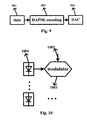
- FIG. 8 is a schematic representation of generating DAPSK signals in frequency domain according to an embodiment of the present invention.
- FIG. 9 is a schematic representation of generating DAPSK signals in time domain according to an embodiment of the present invention.
- FIG. 10 is a schematic representation of generating optical DAPSK signals according to an embodiment of the present invention.
- FIG. 11 is a schematic representation of generating optical DAPSK signals by coherent mapping according to an embodiment of the present invention.
- FIG. 12 is a schematic representation of performing direct detection on optical DAPSK signals according to an embodiment of the present invention.
- FIG. 13 is a schematic representation of performing coherent detection on optical DAPSK signals according to an embodiment of the present invention.
- FIG. 14 is a flow chart showing the procedures executed by the transmitter according to an embodiment of the present invention.
- FIG. 15 is a flow chart showing the procedures executed by the receiver according to an embodiment of the present invention.
- FIG. 16 shows Q value versus receiver OSNR in back-to-back case
- FIG. 17 shows Q value penalty versus accumulated chromatic dispersion
- FIGS. 18( a ) and 18 ( b ) shows Q value versus launch power after 480 km of transmission
- FIGS. 19( a ) and 19 ( b ) shows optical spectrums of a WDM system before and after 480 km of transmission
- FIGS. 20( a ) and 20 ( b ) shows Q value versus launch power after 480 km of transmission.
- the optical communication system may perform encoding at the transmitter on the bit stream data to be transmitted by using a differential encoding technique and have the resultant differentially encoded electrical signals modulated onto optical carriers to generate optical signals for transmission, and may perform decoding at the receiver on the received optical signals by using a corresponding differential decoding technique, so as to obtain the transmitted bit stream data.
- the method according to the present invention can improve the tolerance of the optical communication system for laser linewidth, fast-varying PMD, optical fiber nonlinearity and other damages and thus improve the performances of the communication system by conducting differential modulation on signals at the signal transmitter.
- APSK modulation technique is used as an example to describe the present invention, however, it should be understood that other modulation techniques such as QAM, BPSK, QPSK and so on may be used.
- FIG. 1 shows a block diagram of the differential APSK (DAPSK)-based optical communication system 100 according to the present invention.
- the optical communication system 100 comprises a transmitter 110 and a receiver 120 , wherein the transmitter 110 comprises a modulation unit 111 , a differential encoding unit 113 , a converting unit 115 , a mapping unit 117 and a transmitting unit 119 ; the receiver 120 comprises a receiving unit 121 , a photoelectric conversion unit 122 , a differential decoding unit 125 and a demodulation unit 127 .
- the modulation unit 111 performs modulation on the obtained bit stream data to generate modulated signals.
- the bit stream data may be inputted from the outside, or may be generated by a data signal source inside the transmitter 110 .
- the differential encoding unit 113 performs differential encoding on the modulated signals to generate differentially encoded signals, and send the same to the converting unit 115 .
- the converting unit 115 converts the differentially encoded data into electrical signals.
- the converting unit 115 usually refers to a D/A converting unit, which converts digital signals into analog signals.
- mapping unit 117 maps the electrical signals onto optical carriers to generate optical signals, and the generated optical signals are transmitted by the transmitting unit 119 .
- the transmitter in addition to the modulation unit 111 , the differential encoding unit 113 and the converting unit 115 , the transmitter further comprises a first serial-to-parallel converting unit, an IFFT unit, a cyclic prefix adding unit and a first parallel-to-serial converting unit.
- the differential encoding is performed in time domain, then differentiation is performed on the same sub-carriers of adjacent symbols in the modulated signals during the differential encoding process, which is also referred to as time domain differential encoding.
- the modulation unit 111 performs modulation on the obtained bit stream data to generate modulated signals
- the first serial-to-parallel converting unit performs serial-to-parallel conversion on the modulated signals to generate parallel signals
- the differential encoding unit 113 performs differential encoding on the parallel signals
- the IFFT unit performs inverse Fourier transformation on the differentially encoded signals outputted from the differential encoding unit 113 to transform the signals into time domain from frequency domain.
- the cyclic prefix adding unit adds cyclic prefixes on the signals transformed by the IFFT unit.
- the first parallel-to-serial conversion unit converts the parallel signals outputted from the cyclic prefix adding unit into serial signals (i.e. differentially encoded OFDM signals), and outputs the same into the D/A conversion unit 115 .
- the differential encoding is performed in frequency domain, then differentiation is performed on the adjacent sub-carriers of a same symbol in the modulated signals during the differential encoding process, which is also referred to as frequency domain differential encoding.
- the modulation unit 111 performs modulation on the obtained bit stream data to generate modulated signals
- the differential encoding unit 113 performs differential encoding on the modulated signals.
- the first serial-to-parallel converting unit performs serial-to-parallel conversion on the differentially encoded signals to generate parallel signals
- the IFFT unit performs inverse Fourier transformation on the parallel signals outputted from the first serial-to-parallel conversion unit to transform the signals into time domain from frequency domain.
- the cyclic prefix adding unit adds cyclic prefixes to the IFFT processed signals
- the first parallel-to-serial conversion unit converts the parallel signals outputted from the cyclic prefix adding unit into serial signals (i.e. differentially encoded OFDM signals), and outputs the same to the D/A conversion unit 115 .
- the modulation unit 111 performs modulation on the obtained bit stream data to generate modulated signals, then, the differential encoding unit 113 performs differential encoding on the adjacent symbols in the modulated signals to generate differentially encoded signals. Then, the D/A conversion unit converts the differentially encoded signals into electrical signals.
- the generated electrical signals may be transmitted through single optical carrier or multiple optical carriers.
- the mapping unit 117 is configured to map the electrical signals converted from the differentially encoded signals onto optical carriers to generate light signals.
- the mapping unit 117 may comprise a first laser source and a light signal generating unit.
- the first laser source is configured to generate optical carriers;
- the light signal generating unit is configured to modulate the electrical signals, which are differentially encoded, onto optical carriers to generate light signals for transmission by the transmitting unit.
- the mapping unit 117 may further comprise a first 90 degree light phase shift unit, which is configured to shift the phase of the generated light signals by 90 degrees.
- a receiving unit 121 is configured to receive the light signals transmitted by the transmitter.
- a photoelectric conversion unit 123 is configured to convert the received light signals into corresponding electrical signals.
- a differential decoding unit 125 is configured to perform differential decoding on the electrical signals photoelectrically converted from the light signals.
- a demodulation unit 127 is configured to demodulate the electrical signals, which have been processed by the differential decoding unit, to obtain the bit stream data.
- the photoelectric conversion unit 123 may be a direct detection device or a coherent detection device, depending on whether a direct detection or a coherent detection is adopted in the receiver 220 .
- the direction detection device may comprise a light filter and a photoelectric diode.
- the light filter is configured to extract the optical carrier carrying the required signals.
- the photoelectric diode is configured to convert the light signals into electrical signals.
- the coherent detection device may comprise a light filter, a second laser source, a 90 degree optical hybrid and a photoelectric diode, and may further comprise a light coupler.
- the light filter is configured to extract DAPSK light signals carried by the optical carriers
- the laser source is configured to generate a local optical carrier
- the 90 degree optical hybrid is configured to mix the extracted DAPSK light signals with the local optical carrier
- the photoelectric diode is configured to convert the mixed DAPSK light signals into DAPSK electrical signals.
- the laser source, the 90 degree light hybrid and the photoelectric diode are connected.
- the obtained DAPSK electrical signals may be processed in different manners depending on whether the obtained DAPSK electrical signals are single-carrier signals or multi-carrier signals.
- the receiver may further comprise a second serial-to-parallel conversion unit, a cyclic prefix removing unit, a FFT unit and a second parallel-to-serial conversion unit.
- the second serial-to-parallel conversion unit converts the electrical signals from serial signals into parallel signals
- the cyclic prefix removing unit removes the cyclic prefixes from the parallel signals
- the FFT unit performs Fourier transformation on the cyclic prefix removed signals
- the differential decoding unit performs differential decoding on the parallel signals outputted from the FFT unit
- the second parallel-to-serial conversion unit converts the parallel signals outputted from the differential decoding unit into serial signals, and outputs the serial signals to the demodulation unit for demodulation.
- the second serial-to-parallel conversion unit converts the electrical signals from serial signals into parallel signals.
- the cyclic prefix removing unit removes the cyclic prefixes from the parallel signals
- the FFT unit performs Fourier transformation on the cyclic prefix removed signals
- the second parallel-to-serial conversion unit converts the parallel signals processed by the FFT unit into serial signals
- the differential decoding unit performs differential decoding on the converted serial signals, and outputs the differentially decoded signals to the demodulation unit for demodulation.
- the A/D conversion unit converts the DAPSK electrical signals from analog signals into digital signals.
- the differential decoding unit performs differential decoding on the digitals, wherein the differential decoding performed herein corresponds to the differential encoding performed in the transmitter.
- the differentially decoded data are outputted to the demodulation unit for demodulation, so as to obtain the bit stream data.
- the DAPSK signals either generated in time domain or generated in frequency domain, do not require known data such as training symbols, pilot sub-carriers et. al.
- compensating algorithm such as channel estimation, involving known data such as training symbols, pilot sub-carriers and so on is not necessary in the above-mentioned DAPSK-based multi-carrier optical communication method and system provided by the present invention, and inter-carrier interference can be effectively reduced, and tolerance towards laser linewidth, fast-varying PMD, optical fiber nonlinearity, inter-channel interference and other damages can be improved.
- FIG. 4 is a structural representation of generating f-DAPSK and t-DAPSK signals in frequency domain according to an embodiment of the present invention.
- signals are plotted in time direction and in frequency direction, wherein 401 denotes the vertical axis, i.e., the frequency axis, with the interval being one sub-carrier and 402 denotes the horizontal axis, i.e., the time axis, with the interval being one symbol.
- 403 denotes the data carried on one sub-carrier in one symbol.
- 404 denotes the direction in which f-DAPSK signals are generated by performing differentiation in frequency domain, namely the direction along the adjacent sub-carriers in the same symbol.
- 405 denotes the direction in which t-DAPSK signals are generated by performing differentiation in time domain, namely the direction along the adjacent symbols carried on the same sub-carrier.
- FIG. 5 is a principle schematic diagram of generating and demodulating f-DAPSK and t-DAPSK signals according to the present invention, specifically showing how to generate DAPSK signals and how to implement non-coherent demodulation.
- 501 denotes the complex signal on the k th sub-carrier of the i th symbol after differential encoding
- 502 denotes the complex signal on the k th sub-carrier of the i th symbol before differential encoding
- 503 denotes the complex signal on the k ⁇ 1 th sub-carrier of the i th symbol after differential encoding. Therefore, as far as f-DAPSK signals are concerned, they are obtained by performing differentiation on the information of the adjacent sub-carriers of the same symbol.
- 504 denotes the complex signal on the k th sub-carrier of the i th symbol after differential encoding
- 505 denotes the complex signal on the k th sub-carrier of the i th symbol before differential encoding
- 506 denotes the complex signal on the k th sub-carrier of the i ⁇ 1 th symbol after differential encoding. Therefore, as far as t-DAPSK signals are concerned, they are obtained by performing differentiation on the information of the adjacent symbols carried on the same sub-carrier.
- 507 denotes the signal on the k th sub-carrier of the i th symbol after differential demodulation at the receiver
- 508 denotes the received complex signal on the k th sub-carrier of the i th symbol
- 509 denotes the received complex signal on the k ⁇ 1 th sub-carrier of the i th symbol
- 510 denotes the complex signal on the k th sub-carrier of the i th symbol at the transmitter.
- 511 denotes the complex signal on the k ⁇ 1 th sub-carrier of the i th symbol at the transmitter
- 512 denotes the transfer function factor concerning the k th sub-carrier of the i th symbol
- 513 denotes the transfer function factor concerning the k ⁇ 1 th sub-carrier of the i th symbol
- 514 denotes the complex signal on the k th sub-carrier of the i th symbol before differential encoding at the transmitter
- 515 denotes the transfer function factor concerning the k th sub-carrier of the i th symbol
- 516 denotes the transfer function factor concerning the k ⁇ 1 th sub-carrier of the i th symbol
- 517 denotes the signal on the k th sub-carrier of the i th symbol after differential demodulation
- 518 denotes the received complex signal on the k th sub-carrier of the i th symbol.
- 519 denotes the received complex signal on the k th sub-carrier of the i ⁇ 1 th symbol.
- 520 denotes the complex signal on the k th sub-carrier of the i th symbol at the transmitter, and 521 denotes the complex signal on the k th sub-carrier of the i ⁇ 1 th symbol at the transmitter.
- 522 denotes the transfer function factor concerning the k th sub-carrier of the i th symbol.
- 523 denotes the transfer function factor concerning the k th sub-carrier of the i ⁇ 1 th symbol.
- 524 denotes the complex signal on the k th sub-carrier of the i th symbol before differential encoding at the transmitter.
- 525 denotes the transfer function factor concerning the k th sub-carrier of the i th symbol.
- 526 denotes the transfer function factor concerning the k ⁇ 1 th sub-carrier of the i th symbol.
- FIG. 6 is a constellation map generated according to the present invention with 16APSK signals as an example. It should be noted that, for 16APSK, a symbol contains 4 bits of information, and FIG. 6 shows only one of the 16APSK constellation maps with 8 phases and 2 amplitudes. The same is true for both f-DAPSK and t-DAPSK.
- FIG. 7 is a schematic diagram of a specific way of generating APSK signals according to an embodiment of the present invention with 16APSK signals as an example.
- 701 denotes 3 bits of information for phase modulation, wherein 8 combination modes correspond to 8 phases according to Gray encoding, that is, as labeled with 702 , they represent phase information without performing differential encoding.
- 703 denotes 1 bit of information for amplitude modulation, wherein 2 modes correspond to 2 amplitudes, that is, as labeled with 704 , they represent amplitude information without performing differential encoding.
- FIG. 8 is a structural representation of generating DAPSK signals in case of multi-carrier signals according to the present invention.
- 801 denotes bit stream data.
- 802 denotes performing DAPSK modulation
- 803 denotes converting serial bit streams into parallel bit streams, which is the case for f-DAPSK signals, meanwhile, in the case for t-DAPSK signals, firstly, perform serial-parallel conversion as labeled with 804 , and then perform DAPSK encoding.
- 806 denotes performing inverse Fourier transformation on mapped signals.
- 807 denotes converting parallel signals into serial signals.
- 808 denotes digital/analog conversion that converts digital signals into analog signals.
- FIG. 9 is a schematic representation of generating DAPSK signals in case of single-carrier according to an embodiment of the present invention.
- 901 denotes bit stream data.
- 902 denotes performing DAPSK differential encoding.
- 903 denotes digital/analog conversion that converts digital signals into analog signals.
- FIG. 10 is a schematic representation of generating optical DAPSK signals by direct mapping according to an embodiment of the present invention.
- 1001 denotes a first laser source
- 1002 denotes electrical signals
- 1003 denotes a modulator (i.e. optical signal generating unit) for converting electrical signals into optical signals.
- a plurality of laser sources or other devices may be required to replace the first laser source 1001 to generate optical carriers.
- FIG. 11 is a schematic representation of generating optical DAPSK signals by coherence mapping according to an embodiment of the present invention.
- 1101 denotes a laser source
- 1102 and 1103 denote the in-phase component and the orthogonal component of an electrical signal respectively.
- Modulators 1104 and 1105 convert signals from electrical domain into optical domain, and the orthogonal component further needs to pass a 90° light phase shifter 1106 .
- a plurality of laser sources or other devices may be required to replace the laser source 1101 to generate optical carriers.
- FIG. 12 is a schematic representation of performing direct detection on the optical DAPSK signals according to an embodiment of the present invention.
- 1201 is an optical band-pass filter for selecting the optical carrier carrying the required data signals
- 1202 denotes a photodiode for converting optical signals into electrical signals.
- FIG. 13 is a schematic representation of performing coherent detection on the optical DAPSK signals according to an embodiment of the present invention.
- 1301 denotes a local laser at the receiver.
- 1302 denotes the received signals.
- 1303 denotes a 90° light hybrid.
- 1306 , 1307 , 1308 and 1309 denote 4 photodiodes for balance receiving optical signals, and outputting the in-phase components I and the orthogonal components Q of the signals at the receiver, respectively.
- optical communication systems according to embodiments of the present invention have been described with reference to FIG. 1 to FIG. 13 , and in the following, the operation procedures of the transmitter and the receiver in the optical communication system according to the present invention will be described with reference to FIG. 14 and FIG. 15 , respectively.
- FIG. 14 shows a flow chart of the operation procedures implemented at the transmitter in the optical communication system according to the present invention.
- the obtained bit stream data are modulated to generate modulated signals; then, in the step S 1402 , the modulated signals are differentially encoded to generate differentially encoded signals; subsequently, in the step S 1403 , differentially encoded data are converted into electrical signals; and after that, in the step S 1404 , the electrical signals are mapped onto optical carriers to generate optical signals for transmission.
- the differential encoding is performed in different manners depending on whether the electrical signals are multi-carrier signals or single-carrier signals, the specific procedures have been described in the preceding part with respect to the corresponding parts in the transmitter, and will be repeated herein.
- FIG. 15 shows a flow chart of the operation procedures performed at the receiver in the optical communication system according to the present invention.
- the receiver first of all, in the step S 1510 , the received optical signals are converted into corresponding electrical signals; then, in the step S 1520 , the electrical signals obtained in the photoelectric conversion procedure are differentially decoded; subsequently, in the step S 1530 , the electrical signals after being processed in the differential decoding procedure are demodulated to generate the bit stream data.
- the differential encoding performed on the electrical signals has been described with respect to the receiver in the above description.
- the communication methods and systems provided in the present invention may be not only applicable to baseband optical OFDM systems, but also to RF modulation optical OFDM systems; not only applicable to direct detection optical OFDM systems (DD-OFDM), but also to coherent optical OFDM systems (CO-OFDM); not only applicable to ultra long-haul optical OFDM systems, but also to other optical systems including OFDM-PON systems, which apply the OFDM technology. They are not only applicable to traditional OFDM systems, but also to all-optical OFDM systems. They are further applicable to WDM and Superchannel. Since this approach does not need known data such as training symbols, and pilot sub-carriers, there is no compensating algorithm consumptions. Due to the differential relationship introduced at the transmitter, the present invention can effectively suppress inter-carrier interference and improve system performance.
- the number of the sub-carriers used in the OFDM signals is 165
- the IFFT size used in the IFFT procedure is 256
- no pilot sub-carriers are added to any signals
- one training symbol is added only for 16QAM case
- the length of the cyclic prefix is 10.
- the extinction ratio of the modulator is 100 dB
- the insert loss is 0, and the phase of the laser is 0, now only the laser linewidths at the transmitter and the receiver will be taken into consideration.
- the 16DAPSK scheme with differentiation relation in frequency domain can tolerate a linewidth of 110 kHz
- the 16DAPSK scheme with differentiation relation in time domain can tolerate a linewidth of 45 kHz
- 16QAM scheme can only tolerate a linewidth of 22 kHz.
- the Q value of a 16QAM encoded OFDM system decreases by 6 dBs compared with that of a 16DAPSK encoded system with frequency domain differentiation, and decreases by 4 dBs compared with that of a 16DAPSK encoded system with differentiation relation in time domain.
- the DAPSK encoded system has a significantly improved capability of tolerating phase noise.
- EDFA Er-doped fiber amplifiers
- the optimal launch power for a 16QAM encoded OFDM system is ⁇ 10 dBm, the corresponding Q value is 9.7 dB, while the optimal launch power for a 16DAPSK encoded OFDM system with time domain differentiation is ⁇ 8 dBm, the corresponding Q value is 12.2 dB; the optimal launch power for a 16DAPSK encoded OFDM system with frequency domain differentiation is ⁇ 8 dBm, the corresponding Q value is 11.7 dB.
- the DAPSK encoded systems' tolerance towards nonlinearity is also improved.
- q-OFDM, t-OFDM and f-OFDM denote 16QAM encoded OFDM system, 16DAPSK encoded OFDM system with differentiation relation in time domain, and 16DAPSK encoded OFDM system with differentiation relation in frequency domain, respectively.
- q-OFDM, t-OFDM and f-OFDM denote 16QAM encoded OFDM system, 16DAPSK encoded OFDM system with differentiation relation in time domain, and 16DAPSK encoded OFDM system with differentiation relation in frequency domain, respectively.
- q-OFDM, t-OFDM and f-OFDM denote 16QAM encoded OFDM system
- 16DAPSK encoded OFDM system with differentiation relation in time domain 16DAPSK encoded OFDM system with differentiation relation in frequency domain
- the baseband OFDM signal is generated with a MATLAB program by sequentially performing mapping, serial-to-parallel conversion, training symbol addition, inverse Fourier transformation, cyclic prefix addition and parallel-to-serial conversion on a 2 15 ⁇ 1 pseudorandom binary sequence (PRBS).
- PRBS pseudorandom binary sequence
- 16QAM, 16DAPSK with time domain differentiation, and 16DAPSK with frequency domain differentiation are used for symbol mapping;
- the FFT size is 256, wherein 165 sub-carriers are useful, remaining 91 zero visual sub-carriers are located in the middle of the spectrum.
- cyclic prefix For 16DAPSK encoded OFDM systems, no training symbols or pilot sub-carriers are used, while for 16QAM encoded OFDM system, pilot sub-carriers and training symbols are needed for channel estimation and balance; the cyclic prefix have a length of 10.
- the time duration of one OFDM symbol is 26.6 ns, therefore the guard interval is 1.0 ns and the nominal bit rate (for all data, including the training symbols and effective data) thereof is 40 Gb/s, occupying a bandwidth of less than 6.7 GHz.
- the baseband OFDM signal is processed by a raised cosine filter in order to remove aliasing products and then transformed to optical domain using an I/Q modulator (usually, using dual-parallel modulator).
- the transmission link includes a power controlled EDFA and a recirculating loop.
- the loop has an 80 km standard single mode fiber (SSMF) and a gain controlled EDFA.
- the gain controlled EDFA with a noise figure of 6 dB is used to compensate for the SMF attenuation.
- a 2nd order Gaussian-shaped optical band-pass filter with a bandwidth of 20 GHz is used to filter out ASE noises.
- the coherent receiver consists of a local oscillator (LO), a 90° hybrid, and two balanced detectors. Then the electrical signal filtered is processed with a MATLAB program.
- the first symbol is discarded at the transmitter due to the differential modulation for t-OFDM and f-OFDM.
- q-OFDM one training symbol and no pilot sub-carrier is used, and the resultant spectral efficiency and useful data rate are close to those with t-OFDM and f-OFDM.
- various amounts of training symbols and pilot sub-carriers are applied to q-OFDM in order to obtain similar performance with t-OFDM and f-OFDM, which will decrease the spectrum efficiency and effective bit rate. As shown in FIG. 20 , FIG. 21 and FIG.
- the numbers in brackets represent the interval of pilot sub-carriers and training overhead (which is defined as the number of the training symbols/the number of the useful data symbols) in order. Unless otherwise indicated, one training symbol and no pilot sub-carrier is used for q-OFDM mentioned in simulation.
- FIG. 16 depicts Q value versus receiver OSNR in back-to-back case.
- t-OFDM, f-OFDM and q-OFDM have the similar OSNR requirement towards ASE noise.
- FIG. 17 shows Q value penalty versus accumulated chromatic dispersion (CD) at an OSNR of 15 dB/0.1 nm.
- the tolerance of these three kinds of OFDM systems to accumulated CD is evaluated by transmitting optical OFDM signals through a fiber with only CD effect.
- Q value penalty is defined as the difference from a Q value when there is no CD effect.
- the Q value penalty of f-OFDM is about 1.5 dB larger than that of q-OFDM, while Q penalty difference between t-OFDM and q-OFDM is less than 0.3 dB.
- the reason is that, for f-OFDM the differential modulation among adjacent sub-carriers makes it more sensitive to the phase differences induced by accumulated CD, especially to the large phase variation in the presence of a large CD.
- the minor advantage of q-OFDM over t-OFDM is mainly due to the large constellation spacing of 16QAM.
- FIG. 18 shows Q value versus launch power after 480 km transmission in a single channel case, wherein, in FIG. 18( a ), only one training symbol and no pilot sub-carrier is used for q-OFDM, while in FIG. 18( b ), both training symbols and pilot sub-carriers are used for q-OFDM.
- FIG. 18 depicts the tolerance of the three systems for intra-channel nonlinearity within a channel.
- both t-OFDM and f-OFDM outperform q-OFDM over the launch power range from ⁇ 16 dBm to ⁇ 1 dBm.
- the optimal launch power is ⁇ 10 dBm for q-OFDM and the corresponding Q value is 9.7 dB;
- the optimal launch power of ⁇ 8 dBm is the same for t-OFDM and f-OFDM, while the corresponding Q values are 11.7 dB and 12.2 dB, respectively, indicating at least 2 dB improvement of Q value over q-OFDM.
- pilot sub-carriers and training symbols are used for q-OFDM, as shown in FIG. 18( b ), the improvement is limited, especially when the launch power is high and the nonlinear effect dominates. Furthermore, spectrum bandwidth is increased by about 6.6% ⁇ 9.4% and bit rate is reduced by 1.9% ⁇ 5.6% for q-OFDM.
- FIG. 19 shows the nonlinear effect in a WDM system.
- FIG. 19 shows optical spectrums of 5-channel 50-GHz spaced WDM system over 480 km of SSMF spans before (left) and after (right) transmission.
- XPM cross-phase modulation
- FIG. 20 Simulation results of the OFDM signal of the center channel are shown in FIG. 20 .
- the optimal signal launch power per wavelength channel for t-OFDM, f-OFDM and q-OFDM are ⁇ 9 dBm, ⁇ 9 dBm and ⁇ 11 dBm while the corresponding Q values are 11.4 dB, 11.2 dB and 9.2 dB, respectively, indicating that t-OFDM and f-OFDM has at least 2 dB improvement over q-OFDM.
- FIG. 20( a ) only one training symbol and no pilot subcarrier is used for q-OFDM, and at this time, the optimal signal launch power per wavelength channel for t-OFDM, f-OFDM and q-OFDM are ⁇ 9 dBm, ⁇ 9 dBm and ⁇ 11 dBm while the corresponding Q values are 11.4 dB, 11.2 dB and 9.2 dB, respectively, indicating that
- insertion of training symbols and pilot sub-carriers can properly improve the performances of the system, however, it has similar phenomena as that with single carrier. That is, improvement of performance is limited when the nonlinear effect is dominant, meanwhile spectrum bandwidth is increased by about 6.6% ⁇ 9.4% and bit rate is reduced by 1.9% ⁇ 5.6%.
- f-OFDM the differential modulation is performed among adjacent sub-carriers.
- f-OFDM is more sensitive to the phase differences induced by accumulated CD.
- the differential relation provides a function like a pilot sub-carrier to supply f-OFDM with the strongest robustness towards nonlinear effect.
- t-OFDM the differential relationship is between adjacent symbols, which reduces the influence of CD effect. Therefore, both amplitude differentiation and phase differentiation performed in either frequency domain or time domain have greatly increased the nonlinearity tolerance of OFDM signal not only in single channel but also in WDM environment.
- the differential encoding based optical communication systems provided in the present invention may be directly applied to various optical transmission systems to simplify the systems and reduce the costs while ensuring spectrum efficiency.
- the differential encoding based optical communication method and system provided in the present invention has the following advantages:
- the multi-carrier optical communication systems described in the present invention is suitable for use in various optical communication systems.
Landscapes
- Engineering & Computer Science (AREA)
- Computer Networks & Wireless Communication (AREA)
- Signal Processing (AREA)
- Optical Communication System (AREA)
Abstract
Description
Q 2 Factor (dB)=20×log10(√{square root over (2)}×erfcinv(2×BER))
Claims (10)
Applications Claiming Priority (6)
| Application Number | Priority Date | Filing Date | Title |
|---|---|---|---|
| CN201110274515 | 2011-09-16 | ||
| CN201110274515 | 2011-09-16 | ||
| CN201110274515.7 | 2011-09-16 | ||
| CN201110397065 | 2011-12-02 | ||
| CN2011103970650A CN102427387A (en) | 2011-12-02 | 2011-12-02 | Optical communication method and system |
| CN201110397065.0 | 2011-12-02 |
Publications (2)
| Publication Number | Publication Date |
|---|---|
| US20130070866A1 US20130070866A1 (en) | 2013-03-21 |
| US8718160B2 true US8718160B2 (en) | 2014-05-06 |
Family
ID=47880656
Family Applications (1)
| Application Number | Title | Priority Date | Filing Date |
|---|---|---|---|
| US13/450,894 Expired - Fee Related US8718160B2 (en) | 2011-09-16 | 2012-04-19 | Multi-carrrier optical communication method and system based on DAPSK |
Country Status (1)
| Country | Link |
|---|---|
| US (1) | US8718160B2 (en) |
Families Citing this family (16)
| Publication number | Priority date | Publication date | Assignee | Title |
|---|---|---|---|---|
| ES2621845T3 (en) * | 2012-06-28 | 2017-07-05 | Huawei Technologies Co., Ltd. | Method and device to calculate the reduction of non-linear transmission of fiber optic link |
| MX351475B (en) * | 2013-03-12 | 2017-10-17 | Philips Lighting Holding Bv | A communication system, lighting system and method of transmitting information. |
| TW201445892A (en) * | 2013-05-16 | 2014-12-01 | Inst Information Industry | Transmitter and transmission method thereof |
| US9391724B2 (en) * | 2013-08-16 | 2016-07-12 | Arris Enterprises, Inc. | Frequency sub-band coding of digital signals |
| CN103731241B (en) * | 2014-01-22 | 2017-02-08 | 四川大学 | Encoding system and method for improving spectrum efficiency of communication system |
| CN105917605B (en) * | 2014-02-04 | 2019-03-19 | 华为技术有限公司 | Direct Detection Orthogonal Frequency Division Multiplexing Using Dispersion Precompensation Digital Signal Processing |
| CN104967583B (en) * | 2015-06-01 | 2019-03-19 | 江苏文络电子科技有限公司 | A method of improving differential system receptivity |
| US10178152B2 (en) * | 2016-04-29 | 2019-01-08 | Splunk Inc. | Central repository for storing configuration files of a distributed computer system |
| WO2019027360A1 (en) * | 2017-07-31 | 2019-02-07 | Telefonaktiebolaget Lm Ericsson (Publ) | Differential encoded m-psk in a wireless communication system |
| CN113556178B (en) * | 2020-12-10 | 2023-06-23 | 哈尔滨工业大学(威海) | Aerial and underwater laser-acoustic communication device with improved photoacoustic conversion efficiency and its application |
| CN114050954B (en) * | 2021-11-19 | 2023-02-14 | 大连理工大学 | Metal oil storage tank temperature detection method based on pi/4-QPSK spread spectrum ultrasonic communication |
| CN114422033B (en) * | 2021-12-30 | 2023-06-27 | 湖南国天电子科技有限公司 | Optical fiber isolation communication method and system for onboard power supply of tethered unmanned aerial vehicle |
| CN117675488A (en) * | 2022-08-31 | 2024-03-08 | 维沃移动通信有限公司 | Information processing methods, devices, communication equipment and readable storage media |
| CN116112085B (en) * | 2022-12-30 | 2026-06-02 | 苏州创鑫激光科技有限公司 | An Ethernet carrier modulation and demodulation circuit, a laser bus controller and system |
| CN116054950B (en) * | 2023-01-10 | 2024-05-24 | 华中科技大学 | A method and system for intelligent identification and allocation of optical signals |
| CN117220773B (en) * | 2023-08-24 | 2026-06-16 | 哈尔滨工业大学(威海) | Air-to-water cross-medium laser communication method and system based on noncoherent accumulation |
Citations (8)
| Publication number | Priority date | Publication date | Assignee | Title |
|---|---|---|---|---|
| US20040151255A1 (en) * | 1999-09-17 | 2004-08-05 | Lucent Technologies Inc. | Method and apparatus for identifying an orthogonal frequency division multiplexing (OFDM) terrestrial repeater using inactive sub-carriers |
| CN1604514A (en) | 2003-09-29 | 2005-04-06 | 朗迅科技公司 | System and method for optical transmission |
| US20070076820A1 (en) * | 2005-10-03 | 2007-04-05 | Chih-Yang Kao | Communication system with demodulation of two-level differential amplitude-shift-keying signals |
| US20070104286A1 (en) * | 2005-11-08 | 2007-05-10 | Juinn-Horng Deng | Equipment and method for MIMO SC-FED communication system |
| CN101335556A (en) | 2007-06-29 | 2008-12-31 | 华为技术有限公司 | Distributed multiple-input multiple-output system and its data sending and receiving method |
| US20100034542A1 (en) * | 2007-01-29 | 2010-02-11 | Ofidium Pty Ltd | Methods and apparatus for generation and transmission of optical signals |
| CN101938438A (en) | 2009-06-30 | 2011-01-05 | 华为技术有限公司 | A method, device and optical transmission system for generating and receiving optical signals |
| CN102111374A (en) | 2010-12-22 | 2011-06-29 | 北京邮电大学 | Differential 8-phase shift keying (D8PSK)/amplitude shift keying (ASK) orthogonal light label switching method and system based on differential biphasic codes |
-
2012
- 2012-04-19 US US13/450,894 patent/US8718160B2/en not_active Expired - Fee Related
Patent Citations (8)
| Publication number | Priority date | Publication date | Assignee | Title |
|---|---|---|---|---|
| US20040151255A1 (en) * | 1999-09-17 | 2004-08-05 | Lucent Technologies Inc. | Method and apparatus for identifying an orthogonal frequency division multiplexing (OFDM) terrestrial repeater using inactive sub-carriers |
| CN1604514A (en) | 2003-09-29 | 2005-04-06 | 朗迅科技公司 | System and method for optical transmission |
| US20070076820A1 (en) * | 2005-10-03 | 2007-04-05 | Chih-Yang Kao | Communication system with demodulation of two-level differential amplitude-shift-keying signals |
| US20070104286A1 (en) * | 2005-11-08 | 2007-05-10 | Juinn-Horng Deng | Equipment and method for MIMO SC-FED communication system |
| US20100034542A1 (en) * | 2007-01-29 | 2010-02-11 | Ofidium Pty Ltd | Methods and apparatus for generation and transmission of optical signals |
| CN101335556A (en) | 2007-06-29 | 2008-12-31 | 华为技术有限公司 | Distributed multiple-input multiple-output system and its data sending and receiving method |
| CN101938438A (en) | 2009-06-30 | 2011-01-05 | 华为技术有限公司 | A method, device and optical transmission system for generating and receiving optical signals |
| CN102111374A (en) | 2010-12-22 | 2011-06-29 | 北京邮电大学 | Differential 8-phase shift keying (D8PSK)/amplitude shift keying (ASK) orthogonal light label switching method and system based on differential biphasic codes |
Non-Patent Citations (1)
| Title |
|---|
| The 1st Office Action of the priority application 201110397065.0, Dec. 3, 2013. |
Also Published As
| Publication number | Publication date |
|---|---|
| US20130070866A1 (en) | 2013-03-21 |
Similar Documents
| Publication | Publication Date | Title |
|---|---|---|
| US20130070866A1 (en) | Multi-carrier Optical Communication Method and System Based on DAPSK | |
| US8467687B2 (en) | Optical transmitter and optical OFDM communication system | |
| Darwazeh et al. | Optical SEFDM system; bandwidth saving using non-orthogonal sub-carriers | |
| US9515767B2 (en) | Multi-channel optical transceiver with offset quadrature amplitude modulation | |
| CN101803247B (en) | Pmd insensitive direct-detection optical OFDM systems using self-polarization diversity | |
| EP2559173B1 (en) | Method and device for transmission and reception of a polarization multiplexed optical signal | |
| Zhao et al. | A novel optical fast OFDM with reduced channel spacing equal to half of the symbol rate per carrier | |
| CN102427387A (en) | Optical communication method and system | |
| WO2011151913A1 (en) | Optical communication system, optical receiver, optical transponder, wavelength multiplexing optical communication system, wavelength multiplexing receiving device, and wavelength multiplexing optical transponder | |
| Li et al. | Performance comparison of DFT-spread and pre-equalization for 8× 244.2-Gb/s PDM-16QAM-OFDM | |
| Jung et al. | AMO-FBMC for asynchronous heterogeneous signal integrated optical transmission | |
| WO2012003856A1 (en) | Method and device for data processing in an optical communication network | |
| Zeng et al. | A novel CAP-WDM-PON employing multi-band DFT-spread DMT signals based on optical Hilbert-transformed SSB modulation | |
| Ding et al. | Generation of faster-than-Nyquist coherent optical DFT-spread OFDM signals with high-baud and high-order modulations | |
| Shieh et al. | Experimental demonstration of transmission of coherent optical OFDM systems | |
| Hussin et al. | Performance analysis of RF-pilot phase noise compensation techniques in coherent optical OFDM systems | |
| Gonzalez et al. | Optical phase-modulated radio-over-fiber links with k-means algorithm for digital demodulation of 8PSK subcarrier multiplexed signals | |
| Wang et al. | Performance evaluation of (D) APSK modulated coherent optical OFDM system | |
| Li et al. | Comparison of transmission performances for CO-SCFDE and CO-OFDM systems | |
| Rosenkranz et al. | Orthogonal frequency division multiplexing (OFDM) and other advanced options to achieve 100Gb/s Ethernet transmission | |
| Wu et al. | Coherent optical OFDM scheme with inter-carrier interference self-cancellation and common phase error compensation | |
| Zhang et al. | Channel estimation based on linear interpolation algorithm in DDO-OFDM system | |
| Ge et al. | An efficient channel estimation algorithm for PDM CO-OFDM WDM system | |
| Zhou et al. | Simple and robust chromatic dispersion estimation for RGI-CO-OFDM systems | |
| Li et al. | Constant envelope OFDM scheme for 6PolSK-QPSK |
Legal Events
| Date | Code | Title | Description |
|---|---|---|---|
| AS | Assignment |
Owner name: BEIJING UNIVERSITY OF POSTS AND TELECOMMUNICATIONS Free format text: ASSIGNMENT OF ASSIGNORS INTEREST;ASSIGNORS:WU, JIAN;WANG, HUI;LI, YAN;AND OTHERS;REEL/FRAME:028075/0415 Effective date: 20111024 |
|
| STCF | Information on status: patent grant |
Free format text: PATENTED CASE |
|
| MAFP | Maintenance fee payment |
Free format text: PAYMENT OF MAINTENANCE FEE, 4TH YR, SMALL ENTITY (ORIGINAL EVENT CODE: M2551) Year of fee payment: 4 |
|
| MAFP | Maintenance fee payment |
Free format text: PAYMENT OF MAINTENANCE FEE, 8TH YR, SMALL ENTITY (ORIGINAL EVENT CODE: M2552); ENTITY STATUS OF PATENT OWNER: SMALL ENTITY Year of fee payment: 8 |
|
| FEPP | Fee payment procedure |
Free format text: MAINTENANCE FEE REMINDER MAILED (ORIGINAL EVENT CODE: REM.); ENTITY STATUS OF PATENT OWNER: SMALL ENTITY |
|
| LAPS | Lapse for failure to pay maintenance fees |
Free format text: PATENT EXPIRED FOR FAILURE TO PAY MAINTENANCE FEES (ORIGINAL EVENT CODE: EXP.); ENTITY STATUS OF PATENT OWNER: SMALL ENTITY |
|
| STCH | Information on status: patent discontinuation |
Free format text: PATENT EXPIRED DUE TO NONPAYMENT OF MAINTENANCE FEES UNDER 37 CFR 1.362 |
|
| FP | Lapsed due to failure to pay maintenance fee |
Effective date: 20260506 |