US8714837B2 - Optical fiber connector - Google Patents
Optical fiber connector Download PDFInfo
- Publication number
- US8714837B2 US8714837B2 US13/116,020 US201113116020A US8714837B2 US 8714837 B2 US8714837 B2 US 8714837B2 US 201113116020 A US201113116020 A US 201113116020A US 8714837 B2 US8714837 B2 US 8714837B2
- Authority
- US
- United States
- Prior art keywords
- optical
- signals
- electrical
- optical signals
- optical fiber
- Prior art date
- Legal status (The legal status is an assumption and is not a legal conclusion. Google has not performed a legal analysis and makes no representation as to the accuracy of the status listed.)
- Active, expires
Links
Images


Classifications
-
- G—PHYSICS
- G02—OPTICS
- G02B—OPTICAL ELEMENTS, SYSTEMS OR APPARATUS
- G02B6/00—Light guides; Structural details of arrangements comprising light guides and other optical elements, e.g. couplings
- G02B6/24—Coupling light guides
- G02B6/42—Coupling light guides with opto-electronic elements
-
- G—PHYSICS
- G02—OPTICS
- G02B—OPTICAL ELEMENTS, SYSTEMS OR APPARATUS
- G02B6/00—Light guides; Structural details of arrangements comprising light guides and other optical elements, e.g. couplings
- G02B6/24—Coupling light guides
- G02B6/42—Coupling light guides with opto-electronic elements
- G02B6/4201—Packages, e.g. shape, construction, internal or external details
- G02B6/4246—Bidirectionally operating package structures
-
- G—PHYSICS
- G02—OPTICS
- G02B—OPTICAL ELEMENTS, SYSTEMS OR APPARATUS
- G02B6/00—Light guides; Structural details of arrangements comprising light guides and other optical elements, e.g. couplings
- G02B6/24—Coupling light guides
- G02B6/42—Coupling light guides with opto-electronic elements
- G02B6/4292—Coupling light guides with opto-electronic elements the light guide being disconnectable from the opto-electronic element, e.g. mutually self aligning arrangements
-
- G—PHYSICS
- G02—OPTICS
- G02B—OPTICAL ELEMENTS, SYSTEMS OR APPARATUS
- G02B6/00—Light guides; Structural details of arrangements comprising light guides and other optical elements, e.g. couplings
- G02B6/24—Coupling light guides
- G02B6/26—Optical coupling means
- G02B6/27—Optical coupling means with polarisation selective and adjusting means
- G02B6/2746—Optical coupling means with polarisation selective and adjusting means comprising non-reciprocal devices, e.g. isolators, FRM, circulators, quasi-isolators
Definitions
- Embodiments of the present disclosure relate to optical fiber communication technology, and more particularly to an optical fiber connector.
- Optical fiber greatly improves transmission speed between most communication devices.
- Each optical fiber connector needs 1-5 watt power to drive optical signal transmission according to transceived content.
- a small form-factor pluggable exchange with 48 ports needs divide 48 watt power for the 48 ports to support an optical fiber connector which connects to the small form-factor pluggable exchange.
- the strength of optical signals received by the optical fiber connector from a connected optical fiber is a large excess of need, which leads energy waste. There remains a heretofore unaddressed need to overcome the limitations described.
- FIG. 1 is a schematic diagram of functional modules of an optical fiber connector of one embodiment of the present disclosure
- FIG. 2 is a schematic diagram of functional modules of an optical fiber connector of one embodiment of the present disclosure.
- FIG. 3 is a flowchart of a working method of an optical fiber connector of one embodiment of the present disclosure.
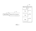
- FIG. 1 is a schematic diagram of application environment of an optical fiber connector 10 of one embodiment of the present disclosure.
- one end of the optical fiber connector 10 connects to an optical fiber 20 to receive optical signals.
- Another end of the optical fiber connector 10 connects to ports 300 of an optical communication device 30 to achieve transmission function between the optical fiber 20 and the optical communication device 30 .
- the optical fiber connector 10 includes small form-factor pluggable (SFP) modules, 10-gigabit small form-factor pluggable (XFP) modules, 10-gigabit Ethernet transceiver package (XENPAK) modules, or other modules to connect to the ports 300 .
- SFP small form-factor pluggable
- XFP 10-gigabit small form-factor pluggable
- XENPAK 10-gigabit Ethernet transceiver package
- the optical fiber connector 10 converts the optical signals received from the optical fiber 20 into electrical signals and transmits the converted electrical signals to the optical communication device 30 . Meanwhile, the optical fiber connector 10 converts electrical signals received from the optical communication device 30 into optical signals and transmits the converted optical signals to an optical network by the optical fiber 20 .
- the optical fiber connector 10 may be a single-fiber bi-directional connector or a two-fiber bi-directional connector.
- the single-fiber bi-directional optical fiber connector 10 connects one fiber 20 to the ports 300 of the optical communication device 30 , and transmits and receives the optical signals with different wavelengths by the one fiber 20 .
- the two-fiber bi-directional optical fiber connector 10 connects two fibers 20 to the ports 300 of the optical communication device 30 , transmits the optical signals by one of the two fibers 20 , and receives the optical signals by another one of the two fibers 20 .
- FIG. 2 is a schematic diagram of application functional modules of the optical fiber connector 10 of one embodiment of the present disclosure.
- the optical fiber connector 10 includes a circular polarizer 101 , a photo detector 102 , an optical electrical converter 103 , and a transceiving module 104 .
- the circular polarizer 101 receives external optical signals from the optical fiber 20 and suitably divides the received optical signals to first optical signals and second optical signals.
- the first optical signals are converted into electrical signals to drive signal transmission of the transceiving module 104 .
- the second optical signals carry transmitted data.
- the circular polarizer 101 comprises a configuration module 1011 .
- the configuration module 1011 sets a default strength of the second optical signals to assure the data carried in the second optical signals are successfully received by the transceiving module 104 .
- the circular polarizer 101 divides the received optical signals to the second optical signals according to the default strength, and divides remainder of the received optical signals to the first optical signals when the strength of the second optical signals reaches the default strength.
- the circular polarizer 101 sets a division ratio according to the default strength, and divides the received optical signals to the first optical signals and the second optical signals according to the division ratio.
- the photo detector 102 detects the first optical signals divided by the circular polarizer 101 , and transmits the first optical signals to the optical electrical converter 103 .
- the photo detector 102 may be an optical diode or a photosensitive resistor to detect and transmit the first optical signals better.
- the optical electrical converter 103 receives the first optical signals from the photo detector 102 , and converts the first optical signals into first electrical signals.
- the power of the first electrical signals is low, normally below 1 watt, which has no affect on the data carried by the second optical signals. It should be noted that, in the future, along with the development of the optical fiber technology, more remaining optical signals of the second optical signals may be converted into electrical signals.
- the optical fiber connector 10 mainly supports the electrical signals to drive the transceiving module 104 .
- Other elements of the optical fiber connector 10 scarcely require the electrical signals.
- power energy required by the optical fiber connector 10 is substantially equal to that of the transceiving module 104 .
- the transceiving module 104 receives the first electrical signals from the optical electrical convertor 103 , receives the second optical signals from the circular polarizer 101 , and receives third electrical signals from the ports 300 of the optical communication device 30 . Then, the first electrical signals are used to drive signal transmission of the transceiving module 104 .
- the transceiving module 104 includes an optical electrical converting circuit 1041 and an electrical optical converting circuit 1042 .
- the optical electrical converting circuit 1041 converts the second optical signals into second electrical signals.
- the first electrical signals drive the transceiving module 104 to transmit the second electrical signals from the optical electrical converting circuit 1041 to the ports 300 of the optical communication device 30 .
- the first group electrical signals drive the transceiving module 104 to transmit the third electrical signals from the ports 300 of the optical communication device 30 to the electrical optical converting circuit 1042 .
- the electrical optical converting circuit 1042 converts the third electrical signals into third optical signals and transmits the third optical signals to the optical fiber 20 .
- the transceiving module 104 receives the second optical signals and transmits the third optical signals by the single fiber. If the optical fiber connector 10 is a two-fiber bi-directional connector, then the transceiving module 104 receives the second optical signals from one of the two fibers and transmits the third optical signals to another one of the two fibers.
- FIG. 2 only shows a main structure of the optical fiber connector 10 . More circuits to adjust the optical or electrical signals, such as an amplifying circuit, or a filtering circuit, could be added to the structure of the optical fiber connector 10 .
- the optical fiber connector 10 can convert surplus of the optical signals received from the optical fiber 20 into electrical signals, and use the electrical signals to drive signal transmission of the optical fiber connector 10 , which decreases power energy requirement from the ports 300 of the optical communication device 30 . Meanwhile, the optical fiber connector 10 decreases power energy waste of the optical signals, which satisfies power save requirement of communication devices which use the optical fiber connector 10 .
- FIG. 3 is a flowchart of a working method of the optical fiber connector 10 of one embodiment of the present disclosure. The flowchart is executed by the modules of the optical fiber connector 10 of FIG. 1 . Depending on the embodiment, additional blocks may be added, others deleted, and the ordering of blocks may be changed while remaining well within the scope of the disclosure.
- the configuration module 1011 sets a default strength of the second optical signals to assure data carried in the second optical signals are successfully transmitted by the transceiving module 104 .
- the circular polarizer 101 receives optical signals from the optical fiber 20 and divides the received optical signals to first optical signals and second optical signals according to the default strength.
- the photo detector 102 detects the first optical signals divided by the circular polarizer 101 , and transmits the first optical signals to the optical electrical converter 103 .
- the optical electrical converter 103 receives the first optical signals from the photo detector 102 , and converts the first optical signals into first electrical signals.
- the optical electrical converting circuit 1041 converts the second optical signals into second electrical signals.
- the transceiving module 104 is driven by the first electrical signals to transmit the second electrical signals from the optical electrical converting circuit 1041 to the ports 300 of the optical communication device 30 .
- the transceiving module 104 is driven by the first electrical signals to transmit the third electrical signals from the ports 300 of the optical communication device 30 to the electrical optical converting circuit 1042 .
- the electrical optical converting circuit 1042 converts the third electrical signals into third optical signals and transmits the third optical signals to the optical fiber 20 .
Landscapes
- Physics & Mathematics (AREA)
- General Physics & Mathematics (AREA)
- Optics & Photonics (AREA)
- Optical Couplings Of Light Guides (AREA)
- Optical Communication System (AREA)
Abstract
Description
Claims (8)
Applications Claiming Priority (3)
| Application Number | Priority Date | Filing Date | Title |
|---|---|---|---|
| CN201020669150 | 2010-12-20 | ||
| CN2010206691509U CN201945716U (en) | 2010-12-20 | 2010-12-20 | Optical fiber connector |
| CN201020669150.9 | 2010-12-20 |
Publications (2)
| Publication Number | Publication Date |
|---|---|
| US20120155886A1 US20120155886A1 (en) | 2012-06-21 |
| US8714837B2 true US8714837B2 (en) | 2014-05-06 |
Family
ID=44473057
Family Applications (1)
| Application Number | Title | Priority Date | Filing Date |
|---|---|---|---|
| US13/116,020 Active 2032-08-31 US8714837B2 (en) | 2010-12-20 | 2011-05-26 | Optical fiber connector |
Country Status (2)
| Country | Link |
|---|---|
| US (1) | US8714837B2 (en) |
| CN (1) | CN201945716U (en) |
Cited By (1)
| Publication number | Priority date | Publication date | Assignee | Title |
|---|---|---|---|---|
| US11165510B2 (en) * | 2019-08-02 | 2021-11-02 | Kyocera Corporation | Power over fiber system and power-supplying-side data communication device of power over fiber system |
Families Citing this family (1)
| Publication number | Priority date | Publication date | Assignee | Title |
|---|---|---|---|---|
| CN105556364B (en) * | 2013-07-03 | 2018-04-13 | 科塞密科技公司 | Hybrid electro-optical data communication cable with wired capacitance compensation |
Citations (5)
| Publication number | Priority date | Publication date | Assignee | Title |
|---|---|---|---|---|
| US5528409A (en) * | 1994-10-13 | 1996-06-18 | Nt International, Inc. | Fiber-optic interface system |
| US6301400B1 (en) | 1998-11-12 | 2001-10-09 | Nxtphase Technologies Srl | Fiber optic current sensor having rotation immunity |
| US20050226625A1 (en) * | 2004-04-09 | 2005-10-13 | Microwave Photonics, Inc. | Optical fiber communications method and system without a remote electrical power supply |
| US8180225B2 (en) * | 2006-12-20 | 2012-05-15 | Jan-Gustav Werthen | Optical data link |
| US8358893B1 (en) * | 2010-01-14 | 2013-01-22 | Sandia Corporation | Photonic-powered cable assembly |
-
2010
- 2010-12-20 CN CN2010206691509U patent/CN201945716U/en not_active Expired - Fee Related
-
2011
- 2011-05-26 US US13/116,020 patent/US8714837B2/en active Active
Patent Citations (5)
| Publication number | Priority date | Publication date | Assignee | Title |
|---|---|---|---|---|
| US5528409A (en) * | 1994-10-13 | 1996-06-18 | Nt International, Inc. | Fiber-optic interface system |
| US6301400B1 (en) | 1998-11-12 | 2001-10-09 | Nxtphase Technologies Srl | Fiber optic current sensor having rotation immunity |
| US20050226625A1 (en) * | 2004-04-09 | 2005-10-13 | Microwave Photonics, Inc. | Optical fiber communications method and system without a remote electrical power supply |
| US8180225B2 (en) * | 2006-12-20 | 2012-05-15 | Jan-Gustav Werthen | Optical data link |
| US8358893B1 (en) * | 2010-01-14 | 2013-01-22 | Sandia Corporation | Photonic-powered cable assembly |
Cited By (1)
| Publication number | Priority date | Publication date | Assignee | Title |
|---|---|---|---|---|
| US11165510B2 (en) * | 2019-08-02 | 2021-11-02 | Kyocera Corporation | Power over fiber system and power-supplying-side data communication device of power over fiber system |
Also Published As
| Publication number | Publication date |
|---|---|
| CN201945716U (en) | 2011-08-24 |
| US20120155886A1 (en) | 2012-06-21 |
Similar Documents
| Publication | Publication Date | Title |
|---|---|---|
| Pepeljugoski et al. | Low power and high density optical interconnects for future supercomputers | |
| EP4431991A1 (en) | Optical module, ferrule and optical fiber connector | |
| CN110176960A (en) | A kind of novel single fiber bi-directional multichannel input optical module | |
| WO2022037511A1 (en) | Light source module and optical communication device | |
| US11585993B2 (en) | Integrated passive optical tap and optical signal termination | |
| CN103259599B (en) | EPON and double-standard optical line terminal optical module | |
| US8606112B2 (en) | Pluggable module with bi-directional host-module optical interface | |
| CN102231652B (en) | C form-factor pluggable (CFP) optical transceiver with interleaver | |
| CN102255669B (en) | C form-factor pluggable (CFP) transponder with interleaver at receiver | |
| CN203838375U (en) | Single-fiber passive single-mode and multi-mode transmission converter and optical fiber transmission system | |
| CN104467972A (en) | 100G QSFP28 SR4 parallel optical transceiver module and packaging method thereof | |
| US8714837B2 (en) | Optical fiber connector | |
| WO2012051088A8 (en) | Compact small form-factor pluggable transceiver | |
| CN107800486A (en) | The compatible pluggable CSFP optical modules of binary channels compact of electrical interface | |
| US10505632B1 (en) | Fiber bus extender embedment | |
| CN202444492U (en) | GBIC (Giga Bitrate Interface Converter) optical module circuit | |
| CN113346954A (en) | Local side equipment used in passive optical network with power of over 50G | |
| CN203166928U (en) | Two-way optical transmit-receive one-piece module based on SFP encapsulation | |
| CN106877936A (en) | A kind of SFP28 optical modules | |
| CN201260169Y (en) | Electric interface used for optical module and optical module having the electric interface | |
| CN112152743A (en) | Ultra-low time delay data broadcasting system and method | |
| CN207689722U (en) | SFP28 single-fiber bidirectional photoelectric module | |
| CN204190773U (en) | A kind of optical module | |
| CN201438232U (en) | Mixed integration-type OLT optical receiving device | |
| CN203761404U (en) | Optical module employing Ethernet passive optical network |
Legal Events
| Date | Code | Title | Description |
|---|---|---|---|
| AS | Assignment |
Owner name: HON HAI PRECISION INDUSTRY CO., LTD., TAIWAN Free format text: ASSIGNMENT OF ASSIGNORS INTEREST;ASSIGNOR:LEE, CHUN-SHENG;REEL/FRAME:026340/0220 Effective date: 20110517 |
|
| STCF | Information on status: patent grant |
Free format text: PATENTED CASE |
|
| MAFP | Maintenance fee payment |
Free format text: PAYMENT OF MAINTENANCE FEE, 4TH YEAR, LARGE ENTITY (ORIGINAL EVENT CODE: M1551) Year of fee payment: 4 |
|
| AS | Assignment |
Owner name: CLOUD NETWORK TECHNOLOGY SINGAPORE PTE. LTD., SING Free format text: ASSIGNMENT OF ASSIGNORS INTEREST;ASSIGNOR:HON HAI PRECISION INDUSTRY CO., LTD.;REEL/FRAME:045171/0306 Effective date: 20171229 |
|
| MAFP | Maintenance fee payment |
Free format text: PAYMENT OF MAINTENANCE FEE, 8TH YEAR, LARGE ENTITY (ORIGINAL EVENT CODE: M1552); ENTITY STATUS OF PATENT OWNER: LARGE ENTITY Year of fee payment: 8 |
|
| MAFP | Maintenance fee payment |
Free format text: PAYMENT OF MAINTENANCE FEE, 12TH YEAR, LARGE ENTITY (ORIGINAL EVENT CODE: M1553); ENTITY STATUS OF PATENT OWNER: LARGE ENTITY Year of fee payment: 12 |