US8708907B2 - Method and apparatus for determining one or more blood parameters from analog electrical signals - Google Patents
Method and apparatus for determining one or more blood parameters from analog electrical signals Download PDFInfo
- Publication number
- US8708907B2 US8708907B2 US12/774,056 US77405610A US8708907B2 US 8708907 B2 US8708907 B2 US 8708907B2 US 77405610 A US77405610 A US 77405610A US 8708907 B2 US8708907 B2 US 8708907B2
- Authority
- US
- United States
- Prior art keywords
- dls
- signal
- processed
- blood
- analog electrical
- Prior art date
- Legal status (The legal status is an assumption and is not a legal conclusion. Google has not performed a legal analysis and makes no representation as to the accuracy of the status listed.)
- Active, expires
Links
Images


Classifications
-
- A—HUMAN NECESSITIES
- A61—MEDICAL OR VETERINARY SCIENCE; HYGIENE
- A61B—DIAGNOSIS; SURGERY; IDENTIFICATION
- A61B5/00—Measuring for diagnostic purposes; Identification of persons
- A61B5/02—Detecting, measuring or recording for evaluating the cardiovascular system, e.g. pulse, heart rate, blood pressure or blood flow
- A61B5/026—Measuring blood flow
- A61B5/0261—Measuring blood flow using optical means, e.g. infrared light
-
- A—HUMAN NECESSITIES
- A61—MEDICAL OR VETERINARY SCIENCE; HYGIENE
- A61B—DIAGNOSIS; SURGERY; IDENTIFICATION
- A61B5/00—Measuring for diagnostic purposes; Identification of persons
- A61B5/02—Detecting, measuring or recording for evaluating the cardiovascular system, e.g. pulse, heart rate, blood pressure or blood flow
- A61B5/021—Measuring pressure in heart or blood vessels
- A61B5/022—Measuring pressure in heart or blood vessels by applying pressure to close blood vessels, e.g. against the skin; Ophthalmodynamometers
- A61B5/02233—Occluders specially adapted therefor
- A61B5/02241—Occluders specially adapted therefor of small dimensions, e.g. adapted to fingers
-
- A—HUMAN NECESSITIES
- A61—MEDICAL OR VETERINARY SCIENCE; HYGIENE
- A61B—DIAGNOSIS; SURGERY; IDENTIFICATION
- A61B5/00—Measuring for diagnostic purposes; Identification of persons
- A61B5/145—Measuring characteristics of blood in vivo, e.g. gas concentration or pH-value ; Measuring characteristics of body fluids or tissues, e.g. interstitial fluid or cerebral tissue
- A61B5/14535—Measuring characteristics of blood in vivo, e.g. gas concentration or pH-value ; Measuring characteristics of body fluids or tissues, e.g. interstitial fluid or cerebral tissue for measuring haematocrit
-
- A—HUMAN NECESSITIES
- A61—MEDICAL OR VETERINARY SCIENCE; HYGIENE
- A61B—DIAGNOSIS; SURGERY; IDENTIFICATION
- A61B5/00—Measuring for diagnostic purposes; Identification of persons
- A61B5/145—Measuring characteristics of blood in vivo, e.g. gas concentration or pH-value ; Measuring characteristics of body fluids or tissues, e.g. interstitial fluid or cerebral tissue
- A61B5/14546—Measuring characteristics of blood in vivo, e.g. gas concentration or pH-value ; Measuring characteristics of body fluids or tissues, e.g. interstitial fluid or cerebral tissue for measuring analytes not otherwise provided for, e.g. ions, cytochromes
-
- A—HUMAN NECESSITIES
- A61—MEDICAL OR VETERINARY SCIENCE; HYGIENE
- A61B—DIAGNOSIS; SURGERY; IDENTIFICATION
- A61B5/00—Measuring for diagnostic purposes; Identification of persons
- A61B5/68—Arrangements of detecting, measuring or recording means, e.g. sensors, in relation to patient
- A61B5/6801—Arrangements of detecting, measuring or recording means, e.g. sensors, in relation to patient specially adapted to be attached to or worn on the body surface
- A61B5/6813—Specially adapted to be attached to a specific body part
- A61B5/6825—Hand
- A61B5/6826—Finger
-
- A—HUMAN NECESSITIES
- A61—MEDICAL OR VETERINARY SCIENCE; HYGIENE
- A61B—DIAGNOSIS; SURGERY; IDENTIFICATION
- A61B5/00—Measuring for diagnostic purposes; Identification of persons
- A61B5/68—Arrangements of detecting, measuring or recording means, e.g. sensors, in relation to patient
- A61B5/6801—Arrangements of detecting, measuring or recording means, e.g. sensors, in relation to patient specially adapted to be attached to or worn on the body surface
- A61B5/683—Means for maintaining contact with the body
- A61B5/6838—Clamps or clips
-
- A—HUMAN NECESSITIES
- A61—MEDICAL OR VETERINARY SCIENCE; HYGIENE
- A61B—DIAGNOSIS; SURGERY; IDENTIFICATION
- A61B5/00—Measuring for diagnostic purposes; Identification of persons
- A61B5/0059—Measuring for diagnostic purposes; Identification of persons using light, e.g. diagnosis by transillumination, diascopy, fluorescence
-
- A—HUMAN NECESSITIES
- A61—MEDICAL OR VETERINARY SCIENCE; HYGIENE
- A61B—DIAGNOSIS; SURGERY; IDENTIFICATION
- A61B5/00—Measuring for diagnostic purposes; Identification of persons
- A61B5/145—Measuring characteristics of blood in vivo, e.g. gas concentration or pH-value ; Measuring characteristics of body fluids or tissues, e.g. interstitial fluid or cerebral tissue
- A61B5/1455—Measuring characteristics of blood in vivo, e.g. gas concentration or pH-value ; Measuring characteristics of body fluids or tissues, e.g. interstitial fluid or cerebral tissue using optical sensors, e.g. spectral photometrical oximeters
Definitions
- the present invention relates to a system and method for in vivo measurement of biological parameters of a mammalian subject (for example, a human) related to blood rheology and/or hemostasis.
- a mammalian subject for example, a human
- the present invention relates to a system and method for in vivo measurement of blood parameters by processing analog electrical signals from a plurality of photodetectors.
- NIRS Near infrared spectroscopy
- Visible or near infrared light is commonly used to track the optical manifestation of some time-dependent physiological processes. Such prolonged measurement of light response as a function of time can provide clinician with valuable information about time-dependent physiological processes.
- the measured light response of a natural heart beat pulsation is varied with each pulse.
- the signal is then measured at one point of the pulse wave and compared with the signal at another point.
- the difference between the values is due to arterial blood alone.
- this phenomenon is utilized for the determination of oxy-hemoglobin saturation.
- the optical time-dependent signal is originated by light scattering changes associated with the red blood cells (RBC) aggregation process.
- the optical signal changes are utilized for the hemoglobin or glucose measurement.
- Yet another known method enables to generate the required changes is the application of a periodic or non-periodic local pressure variation, resulting in blood volume fluctuations. These fluctuations are used to measure different blood parameters, like hemoglobin or glucose.
- the major underlying assumption in the processing of all kind of the time-dependent signals is that the measured optical variation is originated solely by blood related components.
- pulse oximetry for example, it's commonly accepted that arterial blood volume changes are the only responsible factor staying behind the optical signal modulation.
- the measured optical response of these changes is a convolution of absorption and scattering properties of blood and surrounding media. While carrying out any algorithmic modeling and signal processing procedure of these measured optical signals, the tissue related effects can not be disregarded. Therefore, the common denominator of all time-dependent signal related optical methods relies on the measurement of optical responses originated by the blood dynamics or hemorheological status changes.
- the accuracy of time-dependent methods depends on the ability to identify the hemorheological component of the blood.
- the heart beats modulate the hemorheological status of circulating blood, resulting in the fluctuation of RBC velocity, which is associated with the shear forces changes.
- the variation of the hemorheological blood parameters enables to optically distinguish the pulse-related changes of the signal. Therefore, the decreased accuracy in the determination of hemorheological properties leads to a lower accuracy in the determination of the sought blood parameter.
- the blood parameters which can be derived from the hemorheological changes are hemoglobin oxygen saturation, carohyhemoglobin (percentage of HbCO out of total hemoglobin), hemoglobin blood concentration and/or glucose.
- the arterial blood pressure is another physiological parameter, which is commonly derived from the hemorheological related variations.
- the systolic blood pressure can be determined with assistance of inflating cuff which induces hemorheological variations artificially. When a pressure beyond the systolic pressure is applied, no pulsatile waveform appears at the down-flow.
- the diastolic point of the pressure is frequently measured by using Korotkoff's sounds. The source of these sounds is associated with abrupt changes in hemorheological properties of blood, occurring due to deflation of cuff from the systolic point.
- An apparatus for obtaining physiological information from a subject comprises: a) one or more light sources configured to apply partially or entirely coherent light to a target region of the subject to induce a light response signal from the illuminated target region; b) a detection system including: a) a first photodetector configured to detect the light response signal prevailing at a first location to generate a first photodetector analog electrical signal; b) a second photodetector configured to detect the second light response signal prevailing at a second location to generate a second photodetector analog electrical signal, the second location being offset from the first location by an offset distance that is at least 0.1 mm and at most 2 cm; c) an analog electronics assembly configured to generate, from the first and second analog electrical signals, a difference analog electrical signal that is indicative of a difference between the light response signal at the first location and at the second location (in some embodiments, the difference analog signal is indicative of a difference between a light field prevailing at the first location and a light field prevailing at the second location);
- the apparatus further comprises: g) a pressurizing assembly operative to induce a change in blood flow at or near the target region by applying a pressure or a force to the subject's skin.
- this may be useful for determining a blood rheological parameter.
- this may be useful for determining systolic blood pressure to thereby determine RBC aggregation—for example, a rate of aggregation of an average particle size—the skilled artisan is directed to WO 2008/053474 for details.
- the pressurizing assembly includes: i) a strap for constricting blood flow in a subject's finger; and ii) a pneumatic tube for tightening the strap around the subject's finger to constrict the blood flow.
- the pressurizing assembly is operative to create an intermittent blood stasis state by applying over systolic blood pressure to the subject, thereby enabling determination of red blood cell (RBC) aggregation.
- RBC red blood cell
- the digital processing unit is configured: (i) to detect stochastic time-dependent fluctuations in a magnitude of the difference analog electrical signal; and (ii) to compute the at least one physiological parameters in accordance with the detected stochastic fluctuations.
- the digital processing unit is operative to compute a blood velocity and/or blood rheology parameter from the digitized signal.
- the digital processing unit is operative to compute from the digitized signal at least one parameter selected from the group consisting of a blood viscosity, a blood particle size (for example, a central tendency such as an average of RBC aggregates) and a blood coagulation rate.
- the first photodetector is situated at the first location and the second photodetector is situated at the second location, and a distance between the first and second detectors is the offset distance.
- the first and/or second photodetectors are respectively situated away (for example, separated by at least 1 cm or 2 cm or 5 cm or more) from the first and second locations and respectively receive light respectively from the first and/or second location via an optical fiber.
- the digital processing unit is operative to effect at least one of (i) a temporal autocorrelation analysis of the digitized signal; (ii) effecting a power spectrum analysis of the digitized signal, wherein the at least one physiological parameter is computed in accordance with results of the temporal autocorrelation and/or power spectrum analysis.
- the analog electronics assembly i) is configured to receive: A) a first input analog signal derived from the first analog photodetector analog electrical signal; and B) a second input analog signal derived from the second analog photodetector analog electrical signal; and ii) to generate the difference analog electrical signal from a difference between the first and second input signals.
- the one or more light sources are part of an “illuminating system” which may include one or more optical components for example, for focusing the coherent light.
- the coherent light may include wavelengths between 350 nm and 2,000 nm, for example, visible (for example, red) and/or near infra-red (NIR) light.
- visible for example, red
- NIR near infra-red
- the coherent light is red and/or NIR light which may be useful for determining a light of read and blood oxygen saturation and/or a blood hemoglobin concentration.
- the first and/or second photodetector is a Charge-coupled devices (CCD).
- CCD Charge-coupled devices
- a method for obtaining physiological information from a subject in accordance with a light field whose intensity varies according to location comprises: a) applying partially or entirely coherent light to a target region of the subject to induce a light response signal from the illuminated target region which contributes to a location-dependent light field; b) detecting a light field signal prevailing at a first location to generate a first analog signal, the first analog signal including a DLS component that is indicative of a first dynamic light scattering (DLS) measurement; c) detecting a light field signal prevailing at a second location to generate a second analog signal including a DLS component that is indicative of a second dynamic light scattering (DLS) measurement a ratio and that is uncorrelated to the DLS component of the first analog signal; d) processing the first and second analog signals to generate a processed analog signal including a DLS component that is indicative of a combination of the first and second dynamic scattering measurements wherein a ratio between: i) a boosted DLS contribution ratio between a magnitude
- the method further comprises: e) digitizing the processed analog signal to generate a digital signal indicative of a combination of the first and second dynamic scattering measurements; and f) processing the indicative digital signal to compute at least one physiological parameter.
- the computing includes computing at least one of a blood velocity, a blood rheological parameter, a blood pressure, a heartbeat, a blood oxygen concentration, and a pulse.
- the method further comprises: e) before the light field detecting, inducing a change in blood flow at or near the target region.
- the blood flow change inducing is carried out by applying a force or a pressure to the subject.
- the target region is located in a location selected from the group consisting of a finger region, a back region, a leg region, a face region and an arm region.
- the method is carried out so that the first output ratio and/or the second output ratio is at most 0.05
- the method is carried out such that an ambient light component (for example, at one or more specified wavelengths—for example, the wavelength of the coherent light) of the detected light field signal prevailing at the first location is substantially equal to and/or correlated with an ambient light component of the detected light field signal prevailing at the second location.
- an ambient light component for example, at one or more specified wavelengths—for example, the wavelength of the coherent light
- the method is carried out such that a slowly-varying component of the detected light field signal prevailing at the first location is substantially equal to and/or correlated with an slowly-varying component of the detected light field signal prevailing at the second location.
- the method is carried out such that a rapidly-varying non-stochastic rapidly-varying component of the detected light field signal prevailing at the first location is substantially equal to a non-stochastic rapidly-varying component of the detected light field signal prevailing at the second location.
- the method is carried out so that a ratio between an intensity, at a wavelength of the at least partially coherent light, of the detected light field signal prevailing at the first location and intensity, at a wavelength of the at least partially coherent light, of the detected light field signal prevailing at the second location is between 0.95 and 1.05.
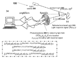
- FIG. 1 is an illustration of a DLS measurement based system for measuring one or more blood parameters (reproduced from WO 2008/053474).
- FIG. 2 is an illustration of a system for generating an analog electrical signal A(t).
- FIGS. 3A-3B and 7 A- 7 B are flow charts of routines for determining at least one blood parameter according to some embodiments.
- FIG. 4 is a circuit diagram of an exemplary analog electronic assembly 270 in accordance with some embodiments.
- FIG. 5 is a diagram of a system for measuring blood parameter(s) including a coherent light source and a plurality of photodetectors.
- FIG. 6 is an illustration of an exemplary apparatus including a pneumatic tube deployed to a subject's finger.
- FIG. 8 is an illustration of the “underside” or “finger-facing surface” of the housing.
- FIG. 9 provides a “cross-section view” of the apparatus of FIG. 6 .
- FIG. 10 illustrates an optical fiber-related embodiment.
- FIGS. 11A-11B illustrate an embodiment where more than one pair of photo detectors is provided.
- WO 2008/053474 discloses a system and method for in vivo measurement of biological parameters.
- WO 2008/053474 discloses a novel optical technique suitable for the in vivo measurement in a subject utilizing dynamic light scattering (DLS) approach.
- DLS dynamic light scattering
- the effect of DLS are utilized for the measurement of variety of blood related parameters, such as viscosity of the blood and blood plasma, blood flow, arterial blood pressure and other blood chemistry and rheology related parameters such as concentration of analyte (e.g. glucose, hemoglobin, etc.), oxygen saturation etc.
- DLS is a well-established technique to provide data on the size and shape of particles from temporal speckle analysis.
- a coherent light beam laser beam, for example
- a scattering (rough) surface a time-dependent fluctuation in the scattering property of the surface and thus in the scattering intensity (transmission and/or reflection) from the surface is observed.
- These fluctuations are due to the fact that the particles are undergoing Brownian or regular flow motion and so the distance between the particles is constantly changing with time.
- This scattered light then undergoes either constructive or destructive interference by the surrounding particles and within this intensity fluctuation information is contained about the time scale of movement of the particles.
- the scattered light is in the form of speckles pattern, being detected in the far diffraction zone.
- the laser speckle is an interference pattern produced by the light reflected or scattered from different parts of an illuminated surface.
- a granular or speckle pattern is produced. If the scattered particles are moving, a time-varying speckle pattern is generated at each pixel in the image. The intensity variations of this pattern contain information about the scattered particles.
- the detected signal is amplified and digitized for further analysis by using the autocorrelation function (ACF) technique.
- ACF autocorrelation function
- the technique is applicable either by heterodyne or by a homodyne DLS setup.
- the kinetics of optical manifestations of two kinds of physiological signals is measured in vivo: the pulsatile signal associated with heart beats and the post-occlusion optical signal which is induced by an artificially generated blood flow cessation.
- the light transmission and/or reflection signals are used as a control of the physiological response. This kind of control measurement can be carried out simultaneously with the DLS reflection measurement.
- the mutual correspondence between DLS and standard optical signals is subject to a comparison analysis.
- FIG. 1 is an illustration of a DLS measurement based system for measuring one or more blood parameters.
- System 100 includes a light source unit 250 (e.g. laser) for generating at least partially coherent light; optical arrangement (not shown) including focusing optics and possibly also collecting optics; and a detection unit including a photodetector 260 .
- a focused beam of light 300 produced by laser 250 e.g., a semiconductor laser
- laser 250 e.g., a semiconductor laser
- a light source unit 250 may be a laser diode (650 nm, 5 mW) or VCSEL (vertical cavity surface emitting laser). The light response i.e.
- the multimode fiber optics may be a bi-furcated randomized optical fiber where one optical entrance is connected to the detector and another one is optically coupled with the laser diode.
- system 100 includes at least one laser diode and at least one photodetector (for example, photodiode(s)) appropriately positioned in the reflection-mode measurement set-up.
- the photodetector 260 is positioned in space at location (x0,y0,z0) and is configured to detect a light field LF(x 0 ,y 0 ,z 0 )—i.e. the light field that exists/prevails at point (x 0 , y o , z o ).
- the light detected by photodetector 260 comes from a number of sources including but not limited to (A) reflected light 310 which is reflected from and/or scattered by the biological tissue; and (ii) ambient light.
- LF( x 0 ,y 0 z 0 ) LF reflected ( x 0 y 0 z 0 )+LF ambient ( x 0 y 0 z 0 )+other terms(s) (EQ. 1)
- LF denotes a light field.
- a first portion of the incident light is reflected from or scattered from “Brownian particles” (i.e. particles undergoing Brownian motion within a liquid—for example, red blood cells or thromobcytes) to generate a first light response signal whose magnitude/intensity varies stochastically and rapidly in time—this first light response signal is referred to as LF reflected — brownian (x 0 , y 0 , z 0 );
- a second portion of the incident light is reflected from stationary biological matter other than Brownian particles—for example, from skin cells, etc—this second portion of the incident light generates a second light response signal whose magnitude/intensity varies at most “slowly” and/or is not stochastic in time—this second light response signal is referred to as LF reflected — non — brownian (x 0 , y 0 , z 0 );
- LF reflected — brownian (x 0 , y 0 , z 0 ) is indicative of a dynamic light scattering parameter.
- Embodiments of the present invention relate to apparatus and methods for “boosting” the relative contribution to an analog electrical signal of a component indicative of a dynamic light scattering measurement—for example, boosting the relative contribution of an analog electrical signal indicative of LF reflected — brownian (x 0 , y 0 , z 0 ).
- LF ambient (x 0 , y 0 , z 0 ) (see Eqn. 1) and LF reflected — non — brownian (x 0 , y 0 , z 0 ) (see Eqn. 2) have an intensity that is either: (i) “slowly” fluctuating (for example, substantially constant or fluctuating at a rate less than 50 HZ); and/or (ii) “regularly behaved” and non-stochastic.
- a “rapidly” fluctuating light signal that is regularly behaved and non-stochastic is light from a fluorescent light bulb operating at 50 HZ or 60 HZ.
- the intensity of “speckles pattern light signal” LF reflected — brownian (x 0 , y 0 , z 0 ) varies stochastically and rapidly—i.e. at a rate that is at least 50 HZ or at least 100 HZ or at least 200 HZ, depending on diffusion coefficient of the Brownian particle.
- LF ⁇ ( x 0 , y 0 , z 0 ) LF slowly ⁇ ⁇ _ ⁇ ⁇ fluctuating ⁇ ( x 0 , y 0 , z 0 ) + [ LF regular ⁇ ( x 0 , y 0 , z 0 ) + LF stochastic ⁇ ( x 0 , y 0 , z 0 ) ] ⁇ rapidly - fluctuating + other ⁇ ⁇ terms ( EQ .
- slowly fluctuating refers to fluctuations at a rate of less than 50 HZ
- rapidly fluctuating refers to regular or stochastic fluctuations at a rate that exceeds 50 HZ (for example, at least 100 HZ or at least 200 HZ).
- LF stochastic (x 0 , y 0 , z 0 ) is the portion of LF(x 0 , y 0 , z 0 ) that may be subjected to DLS analysis to yield one or more blood-related parameters; and (ii) in most clinical situations,
- FIG. 2 is an illustration of a system for generating an analog electrical signal A(t) that includes a relatively “large” component (for example, at least 0.01 or at least 0.1 or at least 0.2 or least 0.3 or at least 0.5 or least 0.8) that is indicative of a time-varying “speckles pattern light signal” received by one or more photo-detectors.
- This analog signal may be converted, using A to D converter or digitizer 204 , into a digital signal D(t).
- the digital signal may be subjected to any analysis described in WO 2008/053474 by digital circuitry 280 to determine one or more blood parameters—for example, temporal autocorrelation or power spectrum techniques.
- the data is collected at 22 KHz sampling rate and 16-bit resolution, and then analyzed by digital circuitry 280 .
- photodetector 260 A for detecting the light field LF(x 1 , y 1 , z 1 ) at location (x 1 , y 1 , z 1 );
- photodetector 260 B for detecting the light field LF(x 2 , y 2 , z 2 ) at location (x 2 , y 2 , z 2 ).
- Photodetector 260 A generates a first analog electrical signal A 1 (t) from LF(x 1 , y 1 , z 1 ) z 1 ).
- Photodetector 260 B generates a second analog electrical signal A 2 (t) from LF(x 2 , y 2 , z 2 ).
- Analog electronics assembly 270 receives the first A 1 (t) and second A 2 (t) analog electrical signals, and generates a “difference” between these two signals A 1 (t)-A 2 (t) to produce analog electrical signal A(t) which is digitized.
- Photodetectors 260 B and 260 B are positioned so that: (i) they are close enough together so that LF ambient (x 1 , y 1 , z 1 ) ⁇ LF ambient (x 2 , y 2 , z 2 ), LF reflected — non — brownian (x 1 , y 1 , z 1 ) ⁇ LF reflected — non — brownian (x 2 , y 2 , z 2 ), LF slowly — fluctuating (x 1 , y 1 , z 1 ) ⁇ LF slowly — fluctuating (x 2 , y 2 , z 2 ) and LF regular (x 1 , y 1 , z 1 ) ⁇ LF regular (x 2 , y 2 , z 2 ); and (ii) they are far enough from each other such that the rapidly fluctuating LF stochastic (x 1 , y 1 , z 1 ) and LF stochastic (x 2 , y 2 , z
- (x 1 , y 1 , z 1 ) and LF stochastic (x 2 , y 2 , z 2 ) in order for LF stochastic (x 1 , y 1 , z 1 ) and LF stochastic (x 2 , y 2 , z 2 ) to be uncorrelated, (x 1 , y 1 , z 1 ) and (x 2 , y 2 , z 2 ) should be separated by at least 0.5 mm—i.e. the offset distance Off of FIGS. 2 and 10 should be at least 0.5 mm.
- A(t) may also include some non-stochastic component. Nevertheless, in typical cases, the relative contribution of the non-stochastic component(s) (i.e., not due to scattering light on Brownian particles to generate a speckles pattern having a rapidly-varying intensity) to analog electric signal A(t) is less than the contribution of respective non-stochastic components to A 1 (t) or A 2 (t).
- This “boosted ratio” may prevail for any length of time—for example, for at least 1 or 3 or 5 seconds.
- FIGS. 3A-3B are flow charts of routines for determining at least one blood parameter according to some embodiments.
- step S 401 light (for example, coherent light from light source 250 ) is applied to a target region of the biological tissue to induce a time-fluctuating light response signal from the illuminated target region.
- step S 405 a light field LF(x 1 , y 1 , z 1 ) prevailing at a first location (x 1 , y 1 , z 1 ) is determined to generate a first A 1 (t) analog electrical signal.
- step S 409 a light field LF(x 2 , y 2 , z 2 ) prevailing at a second location (x 2 , y 2 , z 2 ) is determined to generate a second A 2 (t) analog electrical signal.
- this analog signal is converted into a digital signal (for example, by digitizer 204 ).
- step S 421 this digital signal is analyzed (for example, using any technique disclosed in WO 2008/053474—for example, one or more of temporal autocorrelation or power spectrum techniques) to compute one or more blood parameters.
- FIG. 4 is a circuit diagram of an exemplary analog electronic assembly 270 in accordance with some embodiments.
- “Second cascade” operational amplified U 3 (i) receives as an input voltage 1 (t) and voltage 2 (t), and outputs a signal that is MULT[voltage 1 (t) ⁇ voltage 2 (t)], which is the difference between voltage i (t) and voltage 2 (t) multiplied by a constant whose value is MULT. It is noted that MULT[voltage 1 (t) ⁇ voltage 2 (t)] is one example of A(t) discussed above with reference to FIGS. 2-3 .
- FIG. 5 is a diagram of a system for measuring blood parameter(s) including a coherent light source and a plurality of photodetectors. Light from a light source 300 is incident upon tissue 102 to produce a reflected/scattered light/light response signal 310 which is detected by the photodetectors 260 .
- ⁇ a ⁇ ⁇ ⁇ ⁇ z d ( Eq ⁇ ⁇ 5 )
- ⁇ wavelength of the light.
- z distance between photodiode and the measured object.
- d laser spot diameter.
- N S p ⁇ d 2 ⁇ 2 ⁇ z 2 ( Eq ⁇ ⁇ 6 )
- the mean current, generated by each speckle size element of the photo detector is:
- amplitude of the current fluctuation is proportionally to square root of detector surface. Note, that this relation valid in conditions, when the photodetector collects only a small part of scattered light. This relation can be used to optimize the signal to noise relation.
- FIG. 6 is an illustration of an exemplary apparatus for: (i) inducing a change of blood flow in a subject's biological tissue (for example, in his/her finger or any other location on the subject's body); and (ii) generating an analog electric signal A(t) as discussed above.
- the apparatus of FIG. 6 includes a pneumatic tube 220 and a strap 210 that are mechanically coupled to a device housing 200 .
- Pneumatic tube 220 and strap 210 together form a pressurizing assembly that is operative to induce a change in blood flow.
- the pressurizing assembly including pneumatic tube 220 and strap 210 are operative to induce a change in blood flow in the subject's fingers.
- pressurizing assembly includes some sort of vacuum assembly operative to provide a ‘negative pressure’ to a subject's back, and to induce a change in blood flow in the subject's back.
- FIG. 7A is like FIG. 3A except there is an extra step of applying a force S 397 and/or pressure to a subject's biological tissue (for example, skin) to induce a change in blood flow.
- a force S 397 and/or pressure to induce a change in blood flow.
- carrying out this extra step before effecting the DLS measurement is useful for situations where it is desired to measure one or more of blood viscosity, blood particle size, and blood coagulation rate.
- FIG. 7B is like FIG. 3B except there is an extra step of applying a force S 397 and/or pressure to a subject's biological tissue (for example, skin) to induce a change in blood flow.
- a force S 397 and/or pressure to induce a change in blood flow.
- FIG. 8 is an illustration of the “underside” or “finger-facing surface” of housing 200 .
- FIG. 9 provides a “cross-section view” of the apparatus of FIG. 6 .
- photodetectors 260 A and 260 B are separated by an “Offset distance” Off whose value is selected as discussed above—thus, photodetector 260 A is located at position (x 1 ,y 1 ,z 1 ) and photodetector 260 B is located at position (x2,y2,z2).
- photodetector 260 A is located at a distance (for example, at least 1 or 3 or 5 or 10 cm) from (x 1 ,y 1 ,z 1 ) and receives the optical signal of the light field prevailing at (x 1 ,y 1 ,z 1 ) via optical fiber 290 and/or photodetector 260 B is located at a distance (for example, at least 1 or 3 or 5 or 10 cm) from (x 2 ,y 2 ,z 2 ) and receives the optical signal of the light field prevailing at (x 2 ,y 2 ,z 2 ) via another optical fiber 290 .
- more than one pair of photo detectors may be provided, and some sort of averaging between results associated with each pair of photodetectors may be computed, in order to determine a more accurate assessment of the subject's physiological parameter(s).
- the behavior of a DLS related parameter (d(ln(G)/dt)) utilized for the determination of systolic and diastolic blood pressure where correlation function G( ⁇ ) of temporal intensity fluctuations of light scattered by moving particles is given by:
- G ⁇ ( ⁇ ) ⁇ I ⁇ ( t ) ⁇ I ⁇ ( t + ⁇ ) > ⁇ I ⁇ ( t ) ⁇ > 2 .
- a pressurizing cuff for example, including pneumatic tube 210 and strap 220
- a pressurizing cuff is inflated up to over systolic pressure of 200 mm Hg during the first 5 seconds.
- the air pressure in the cuff is gradually reduced.
- the DLS measurement is carried out at the area beneath the cuff.
- the parameter d(Ln(G))/dt reaches its minimum point when the pressure measured in the cuff gets equal to the systolic pressure, as was defined previously by doing a standard blood pressure measurement test.
- This very unique sensitivity of DLS related parameters to the blood flow can be used for identification of blood flow disturbances or even for blood stasis identification and verification.
- any kind of a medical tool such as intro-vascular catheter (e.g. used for angioplasty) can be linked with DLS equipped optical fiber.
- intro-vascular catheter e.g. used for angioplasty
- blood circulation parameters measured by DLS technique can by embedded as an inherent part of new emerging technology of biofeedback.
- different body parameters including the blood flow that can be beneficial to control emotional status, cardio-vascular training, rehabilitation and other purposes can be controlled.
- such a system can be used for the control of blood flow during recovery from heart failure.
- DLS based measurement system can be combined with facilities affecting the mental status of a subject. For example, a method of binaural beats can be used. The binaural beats are resulted from the interaction of two different auditory impulses, originating in opposite ears.
- the binaural beat is not heard but is perceived as an auditory beat and theoretically can be used to entrain specific neural rhythms through the frequency-following response (FFR), i.e. the tendency for cortical potentials to entrain to or resonate at the frequency of an external stimulus.
- FFR frequency-following response
- a consciousness management technique can be utilized to entrain a specific induction of sympathetic and parasympathetic system.
- biofeedback system based on the methods of binaural beats can be governed by the parameters of flowing blood measured by means of DLS.
- photodetectors 260 A and 260 B may be (i) attached to housing 200 and/or (ii) integrally formed with housing 200 and/or (iii) rigidly maintained at a fixed distance from each other (for example, using housing 200 ).
- Digital circuitry 280 or digital processing unit 280 may include any software/computer readable code module and/or firmware and/or hardware element(s) including but not limited to a CPU, volatile or non-volatile memory, field programmable logic array (FPLA) element(s), hard-wired logic element(s), field programmable gate array (FPGA) element(s), and application-specific integrated circuit (ASIC) element(s).
- Any instruction set architecture may be used in digital circuitry 280 including but not limited to reduced instruction set computer (RISC) architecture and/or complex instruction set computer (CISC) architecture.
- any feature or combination of features WO 2008/053474 may be provided.
- any of the embodiments described above may further include receiving, sending or storing instructions and/or data that implement the operations described above in conjunction with the figures upon a computer readable medium.
- a computer readable medium may include storage media or memory media such as magnetic or flash or optical media, e.g. disk or CD-ROM, volatile or non-volatile media such as RAM, ROM, etc. as well as transmission media or signals such as electrical, electromagnetic or digital signals conveyed via a communication medium such as network and/or wireless links
Landscapes
- Health & Medical Sciences (AREA)
- Life Sciences & Earth Sciences (AREA)
- Physics & Mathematics (AREA)
- General Health & Medical Sciences (AREA)
- Veterinary Medicine (AREA)
- Engineering & Computer Science (AREA)
- Biomedical Technology (AREA)
- Heart & Thoracic Surgery (AREA)
- Medical Informatics (AREA)
- Molecular Biology (AREA)
- Surgery (AREA)
- Animal Behavior & Ethology (AREA)
- Biophysics (AREA)
- Public Health (AREA)
- Pathology (AREA)
- Cardiology (AREA)
- Optics & Photonics (AREA)
- Physiology (AREA)
- Vascular Medicine (AREA)
- Hematology (AREA)
- Dentistry (AREA)
- Ophthalmology & Optometry (AREA)
- Measurement Of The Respiration, Hearing Ability, Form, And Blood Characteristics Of Living Organisms (AREA)
- Measuring Pulse, Heart Rate, Blood Pressure Or Blood Flow (AREA)
Abstract
Description
LF(x 0 ,y 0 z 0)=LFreflected(x 0 y 0 z 0)+LFambient(x 0 y 0 z 0)+other terms(s) (EQ. 1)
Throughout the present disclosure, LF denotes a light field.
LFreflected(x 0 ,y 0 ,z 0)=LFreflected
is “small” (for example, less than 0.1 or less than 0.01 or even smaller).
Embodiments of the present invention relate to apparatus and methods for “boosting” the relative contribution to an analog electrical signal of a component indicative of a dynamic light scattering measurement—for example, boosting the relative contribution of an analog electrical signal indicative of LFreflected
where (i) LFslowly
is relatively “small” (for example, less than 0.1 or less than 0.01 or even smaller).
A First Discussion of a System Including Two Closely-Coupled Photodetectors with Reference to
-
- (i) a first DLS contribution ratio between (A) a magnitude of a “DLS component” of analog signal A1(t) (i.e. a component that is indicative of a DLS measurement—i.e. indicative of LFstochastic(x1, y1, z1) or LFBrownian(x1, y1, z1)) and (B) A1(t), i.e.
-
- in many clinical situations, this first DLS ratio is at most 0.1 or at most 0.05 or at most 0.02 or at most 0.01, or even less.
- (ii) a second DLS contribution ratio between (A) a magnitude of a “DLS component” of analog signal A2(t) (i.e. a component that is indicative of a DLS measurement—i.e. indicative of LFstochastic(x2, y2, z2) or LFBrownian(x2, y2, z2)) and (B) A2(t), i.e.
-
- in many clinical situations, this second DLS ratio is at most 0.1 or at most 0.05 or at most 0.02 or at most 0.01, or even less.
- (iii) a “boosted DLS contribution ratio” between (A) a magnitude of a “DLS component” of processed analog signal A(t) (i.e. a component that is indicative of a DLS measurement(s)—i.e. indicative of a combination of (i) LFstochastic(x1, y1, z1) or LFBrownian(x1, y1, z1)) and (ii) LFstochastic(x2, y2, z2) or LFBrownian(x2, y2, z2)) and (B) A2(t), i.e.
-
- in many clinical situations, this “boosted” DLS ratio exceeds the first and second DLS ratios is at least 0.05 or at least 0.1 or at least 0.2 or at least 0.5.
In some embodiments, a ratio between the “boosted DLS contribution ratio” and the “first DLS contribution ratio” and/or the “second DLS contribution ratio” is at least 3 or at least 5 or at least 10 or at least 20 or at least 50 or at least 100.
- in many clinical situations, this “boosted” DLS ratio exceeds the first and second DLS ratios is at least 0.05 or at least 0.1 or at least 0.2 or at least 0.5.
Where
λ—wavelength of the light.
z—distance between photodiode and the measured object.
d—laser spot diameter.
So SNR≠f(Sp) and proportionally depend of the square root of the power flux on the photodetector.
A Discussion of
Claims (12)
Priority Applications (2)
| Application Number | Priority Date | Filing Date | Title |
|---|---|---|---|
| US12/774,056 US8708907B2 (en) | 2009-05-06 | 2010-05-05 | Method and apparatus for determining one or more blood parameters from analog electrical signals |
| US13/292,110 US20120130215A1 (en) | 2010-05-05 | 2011-11-09 | Optical measurement of parameters related to motion of light-scattering particles within a fluid by manipulating analog electrical signals |
Applications Claiming Priority (2)
| Application Number | Priority Date | Filing Date | Title |
|---|---|---|---|
| US17598109P | 2009-05-06 | 2009-05-06 | |
| US12/774,056 US8708907B2 (en) | 2009-05-06 | 2010-05-05 | Method and apparatus for determining one or more blood parameters from analog electrical signals |
Related Parent Applications (1)
| Application Number | Title | Priority Date | Filing Date |
|---|---|---|---|
| PCT/US2010/056282 Continuation-In-Part WO2012064326A1 (en) | 2010-05-05 | 2010-11-10 | Optical measurement of parameters related to motion of light-scattering particles within a fluid by manipulating analog electrical signals |
Related Child Applications (1)
| Application Number | Title | Priority Date | Filing Date |
|---|---|---|---|
| US13/292,110 Continuation-In-Part US20120130215A1 (en) | 2010-05-05 | 2011-11-09 | Optical measurement of parameters related to motion of light-scattering particles within a fluid by manipulating analog electrical signals |
Publications (2)
| Publication Number | Publication Date |
|---|---|
| US20100286497A1 US20100286497A1 (en) | 2010-11-11 |
| US8708907B2 true US8708907B2 (en) | 2014-04-29 |
Family
ID=43062751
Family Applications (1)
| Application Number | Title | Priority Date | Filing Date |
|---|---|---|---|
| US12/774,056 Active 2031-06-25 US8708907B2 (en) | 2009-05-06 | 2010-05-05 | Method and apparatus for determining one or more blood parameters from analog electrical signals |
Country Status (1)
| Country | Link |
|---|---|
| US (1) | US8708907B2 (en) |
Cited By (1)
| Publication number | Priority date | Publication date | Assignee | Title |
|---|---|---|---|---|
| CN106651967A (en) * | 2016-10-18 | 2017-05-10 | 北京博瑞彤芸文化传播股份有限公司 | Blood viscosity monitoring method based on image processing |
Families Citing this family (11)
| Publication number | Priority date | Publication date | Assignee | Title |
|---|---|---|---|---|
| US8708907B2 (en) | 2009-05-06 | 2014-04-29 | Elfi-Tech | Method and apparatus for determining one or more blood parameters from analog electrical signals |
| US20120184831A1 (en) * | 2011-01-18 | 2012-07-19 | Radiation Monitoring Devices, Inc. | Systems, devices and methods for monitoring hemodynamics |
| US9848787B2 (en) * | 2012-02-07 | 2017-12-26 | Laser Associated Sciences, Inc. | Perfusion assessment using transmission laser speckle imaging |
| US11206990B2 (en) * | 2013-01-23 | 2021-12-28 | Pedra Technology Pte Ltd | Deep tissue flowmetry using diffuse speckle contrast analysis |
| KR102242947B1 (en) | 2013-03-11 | 2021-04-22 | 유니버시티 오브 유타 리서치 파운데이션 | Sensor systems |
| US20150141766A1 (en) * | 2013-09-30 | 2015-05-21 | Flfi-Tfch Ltd. | Apparatus and method for optical measurement of cardiovascular recovery and/or repiration rate |
| US10952622B2 (en) | 2015-11-01 | 2021-03-23 | Elfi-Tech Ltd. | Method and apparatus for hemodynamically characterizing a neurological or fitness state by dynamic light scattering (DLS) |
| US11134901B2 (en) | 2016-03-30 | 2021-10-05 | Elfi-Tech Ltd. | Method and apparatus for optically measuring blood pressure |
| US11350837B2 (en) | 2016-03-30 | 2022-06-07 | Elfi-Tech Ltd. | Method and apparatus for optically measuring blood pressure |
| WO2023158043A1 (en) | 2022-02-16 | 2023-08-24 | Samsung Electronics Co., Ltd. | Method and device for measuring heart rate |
| CN119846942A (en) * | 2025-03-18 | 2025-04-18 | 中国科学院光电技术研究所 | Self-correction control method, equipment and storage medium based on folding least square parameter identification |
Citations (25)
| Publication number | Priority date | Publication date | Assignee | Title |
|---|---|---|---|---|
| US4476875A (en) * | 1978-10-31 | 1984-10-16 | Nilsson Gert E | Method and apparatus for measuring flow motions in a fluid |
| US5219962A (en) | 1991-01-02 | 1993-06-15 | Phillips Petroleum Company | Fluorided aluminas, catalysts, and polymerization processes |
| US5284149A (en) * | 1992-01-23 | 1994-02-08 | Dhadwal Harbans S | Method and apparatus for determining the physical characteristics of ocular tissue |
| US5598841A (en) * | 1993-09-24 | 1997-02-04 | Kowa Company Ltd. | Blood flow measurement system |
| US5817025A (en) * | 1996-09-30 | 1998-10-06 | Alekseev; Sergei Grigorevich | Method for diagnosing malignancy diseases |
| US6259936B1 (en) * | 1997-02-19 | 2001-07-10 | Moor Instruments Limited | Apparatus for imaging blood flow in the microcirculation |
| US6263227B1 (en) * | 1996-05-22 | 2001-07-17 | Moor Instruments Limited | Apparatus for imaging microvascular blood flow |
| US20020077535A1 (en) | 1999-03-09 | 2002-06-20 | Orsense Ltd. | Device for enhancement and quality improvement of blood-related signals for use in a system for non-invasive measurements of blood-related signals |
| US20020173709A1 (en) | 2000-03-15 | 2002-11-21 | Ilya Fine | Probe for use in non-invasive measurements of blood related parameters |
| US20030069487A1 (en) | 2001-10-10 | 2003-04-10 | Mortara Instrument, Inc. | Method and apparatus for pulse oximetry |
| US20030137650A1 (en) | 2000-06-11 | 2003-07-24 | Ilya Fine | Method and device for measuring concentration of glucose or other substances in blood |
| US20040000242A1 (en) | 2002-05-07 | 2004-01-01 | Man Roland Druckmaschinen Ag | Distribution drive for a roll in a processing machine such as a printing press |
| US20040176671A1 (en) | 1999-12-22 | 2004-09-09 | Orsense Ltd. | Method of optical measurements for determining various parameters of the patient's blood |
| US20040225205A1 (en) | 2003-05-06 | 2004-11-11 | Orsense Ltd. | Glucose level control method and system |
| US20040249252A1 (en) | 2003-06-03 | 2004-12-09 | Orsense Ltd. | Method and system for use in non-invasive optical measurements of blood parameters |
| US20050101846A1 (en) | 2003-11-06 | 2005-05-12 | Ilya Fine | Method and system for non-invasive determination of blood-related parameters |
| US20060009685A1 (en) | 2004-07-08 | 2006-01-12 | Orsense Ltd. | Device and method for non-invasive optical measurements |
| US20070232940A1 (en) | 2006-04-03 | 2007-10-04 | Elfi-Tech Ltd | Methods and apparatus for non-invasive determination of patient's blood conditions |
| WO2007144880A2 (en) | 2006-06-13 | 2007-12-21 | Elfi-Tech Ltd. | System and method for measurement of biological parameters of a subject |
| WO2008053474A2 (en) | 2006-10-30 | 2008-05-08 | Elfi-Tech Ltd. | System and method for in vivo measurement of biological parameters |
| US20090091741A1 (en) * | 2007-10-03 | 2009-04-09 | Aristide Dogariu | Optical coagulation monitor and method of use |
| US20090209934A1 (en) | 2004-12-23 | 2009-08-20 | Hospira, Inc. | Port closure system for intravenous fluid container |
| US20100286497A1 (en) | 2009-05-06 | 2010-11-11 | Ilya Fine | Method and Apparatus for Determining One or More Blood Parameters From Analog Electrical Signals |
| US20110082355A1 (en) | 2009-07-30 | 2011-04-07 | Oxitone Medical Ltd. | Photoplethysmography device and method |
| US20120130215A1 (en) | 2010-05-05 | 2012-05-24 | Ilya Fine | Optical measurement of parameters related to motion of light-scattering particles within a fluid by manipulating analog electrical signals |
-
2010
- 2010-05-05 US US12/774,056 patent/US8708907B2/en active Active
Patent Citations (32)
| Publication number | Priority date | Publication date | Assignee | Title |
|---|---|---|---|---|
| US4476875A (en) * | 1978-10-31 | 1984-10-16 | Nilsson Gert E | Method and apparatus for measuring flow motions in a fluid |
| US5219962A (en) | 1991-01-02 | 1993-06-15 | Phillips Petroleum Company | Fluorided aluminas, catalysts, and polymerization processes |
| US5284149A (en) * | 1992-01-23 | 1994-02-08 | Dhadwal Harbans S | Method and apparatus for determining the physical characteristics of ocular tissue |
| US5598841A (en) * | 1993-09-24 | 1997-02-04 | Kowa Company Ltd. | Blood flow measurement system |
| US6263227B1 (en) * | 1996-05-22 | 2001-07-17 | Moor Instruments Limited | Apparatus for imaging microvascular blood flow |
| US5817025A (en) * | 1996-09-30 | 1998-10-06 | Alekseev; Sergei Grigorevich | Method for diagnosing malignancy diseases |
| US6259936B1 (en) * | 1997-02-19 | 2001-07-10 | Moor Instruments Limited | Apparatus for imaging blood flow in the microcirculation |
| US20020077535A1 (en) | 1999-03-09 | 2002-06-20 | Orsense Ltd. | Device for enhancement and quality improvement of blood-related signals for use in a system for non-invasive measurements of blood-related signals |
| US20040176671A1 (en) | 1999-12-22 | 2004-09-09 | Orsense Ltd. | Method of optical measurements for determining various parameters of the patient's blood |
| US20060200014A1 (en) | 1999-12-22 | 2006-09-07 | Orsense Ltd. | Method of optical measurements for determining various parameters of the patient's blood |
| US20020173709A1 (en) | 2000-03-15 | 2002-11-21 | Ilya Fine | Probe for use in non-invasive measurements of blood related parameters |
| US20030137650A1 (en) | 2000-06-11 | 2003-07-24 | Ilya Fine | Method and device for measuring concentration of glucose or other substances in blood |
| US20030069487A1 (en) | 2001-10-10 | 2003-04-10 | Mortara Instrument, Inc. | Method and apparatus for pulse oximetry |
| US20040000242A1 (en) | 2002-05-07 | 2004-01-01 | Man Roland Druckmaschinen Ag | Distribution drive for a roll in a processing machine such as a printing press |
| US20040225205A1 (en) | 2003-05-06 | 2004-11-11 | Orsense Ltd. | Glucose level control method and system |
| US20040249252A1 (en) | 2003-06-03 | 2004-12-09 | Orsense Ltd. | Method and system for use in non-invasive optical measurements of blood parameters |
| US20060129040A1 (en) | 2003-06-03 | 2006-06-15 | Orsense Ltd. | Method and system for use in non-invasive optical measurements of blood parameters |
| US20070078312A1 (en) | 2003-11-06 | 2007-04-05 | Orense Ltd. | Method and system for non-invasive measurements in a human body |
| US20050101846A1 (en) | 2003-11-06 | 2005-05-12 | Ilya Fine | Method and system for non-invasive determination of blood-related parameters |
| US20060009685A1 (en) | 2004-07-08 | 2006-01-12 | Orsense Ltd. | Device and method for non-invasive optical measurements |
| US20090209934A1 (en) | 2004-12-23 | 2009-08-20 | Hospira, Inc. | Port closure system for intravenous fluid container |
| US20070232940A1 (en) | 2006-04-03 | 2007-10-04 | Elfi-Tech Ltd | Methods and apparatus for non-invasive determination of patient's blood conditions |
| WO2007113804A2 (en) | 2006-04-03 | 2007-10-11 | Elfi-Tech Ltd | Methods and appratus for non-invasive determination of patient's blood conditions |
| US20110033385A1 (en) | 2006-04-03 | 2011-02-10 | Elfi-Tech Ltd. | Methods and apparatus for non-invasive determination of patient's blood conditions |
| WO2007144880A2 (en) | 2006-06-13 | 2007-12-21 | Elfi-Tech Ltd. | System and method for measurement of biological parameters of a subject |
| US20090082642A1 (en) | 2006-06-13 | 2009-03-26 | Elfi-Tech Ltd. | System and method for measurement of biological parameters of a subject |
| WO2008053474A2 (en) | 2006-10-30 | 2008-05-08 | Elfi-Tech Ltd. | System and method for in vivo measurement of biological parameters |
| US20090209834A1 (en) | 2006-10-30 | 2009-08-20 | Elfi-Tech Ltd. | System and Method for In Vivo Measurement of Biological Parameters |
| US20090091741A1 (en) * | 2007-10-03 | 2009-04-09 | Aristide Dogariu | Optical coagulation monitor and method of use |
| US20100286497A1 (en) | 2009-05-06 | 2010-11-11 | Ilya Fine | Method and Apparatus for Determining One or More Blood Parameters From Analog Electrical Signals |
| US20110082355A1 (en) | 2009-07-30 | 2011-04-07 | Oxitone Medical Ltd. | Photoplethysmography device and method |
| US20120130215A1 (en) | 2010-05-05 | 2012-05-24 | Ilya Fine | Optical measurement of parameters related to motion of light-scattering particles within a fluid by manipulating analog electrical signals |
Non-Patent Citations (4)
| Title |
|---|
| PCT Search opinion of PCT/US10/56282. |
| PCT Search report of PCT/US10/56282. |
| U.S. Appl. No. 12/431,469 through Aug. 25, 2012. |
| USPTO office action (Non-final rejection) for U.S. Appl. No. 13/292,110-office action was mailed on Nov. 21, 2013. |
Cited By (2)
| Publication number | Priority date | Publication date | Assignee | Title |
|---|---|---|---|---|
| CN106651967A (en) * | 2016-10-18 | 2017-05-10 | 北京博瑞彤芸文化传播股份有限公司 | Blood viscosity monitoring method based on image processing |
| CN106651967B (en) * | 2016-10-18 | 2019-11-05 | 北京博瑞彤芸文化传播股份有限公司 | Blood viscosity monitoring method based on image procossing |
Also Published As
| Publication number | Publication date |
|---|---|
| US20100286497A1 (en) | 2010-11-11 |
Similar Documents
| Publication | Publication Date | Title |
|---|---|---|
| US8708907B2 (en) | Method and apparatus for determining one or more blood parameters from analog electrical signals | |
| US20120130215A1 (en) | Optical measurement of parameters related to motion of light-scattering particles within a fluid by manipulating analog electrical signals | |
| EP2637559B1 (en) | Optical measurement of parameters related to motion of light-scattering particles within a fluid by manipulating analog electrical signals | |
| US9149216B2 (en) | Photoplethysmography device and method | |
| US8277384B2 (en) | System and method for in vivo measurement of biological parameters | |
| US10813597B2 (en) | Non-invasive hemodynamic assessment via interrogation of biological tissue using a coherent light source | |
| US7254432B2 (en) | Method and device for non-invasive measurements of blood parameters | |
| US9480407B2 (en) | Device and method for removal of ambient noise signal from a photoplethysmograph | |
| US20110082355A1 (en) | Photoplethysmography device and method | |
| US20180160913A1 (en) | System and method for in vivo measurement of biological parameters | |
| US20210068717A1 (en) | Blood glucose monitoring method and wearable blood glucose monitoring device using same | |
| US20210022623A1 (en) | Non-invasive hemodynamic assessment via interrogation of biological tissue using a coherent light source | |
| Vinciguerra et al. | PPG/ECG multisite combo system based on SiPM technology | |
| CN101808570A (en) | Blood oxygen meter | |
| US20150141766A1 (en) | Apparatus and method for optical measurement of cardiovascular recovery and/or repiration rate | |
| JP5039123B2 (en) | Finger artery elasticity measurement program, finger artery elasticity measurement device, and finger artery elasticity measurement method | |
| US20150238091A1 (en) | Photoacoustic monitoring technique with noise reduction | |
| US20240156355A1 (en) | Hemodilution detector | |
| US20180153420A1 (en) | Apparatus and method for optical measurement of cardiovascular fitness, stress and physiological parameters | |
| US10772513B2 (en) | Blood pressure ratio calculation device, blood pressure ratio calculation method, blood pressure ratio calculation program, and recording medium recording said program | |
| JP2002541892A (en) | Method of improved calibration of blood monitoring devices | |
| Bachir | Diffuse transmittance visible spectroscopy using smartphone flashlight for photoplethysmography and vital signs measurements | |
| JP6412956B2 (en) | Biological light measurement device, analysis device, and method | |
| Huang et al. | Plantar Perfusion Imaging for Peripheral Arterial Disease Screening: A Proof-of-Concept Study |
Legal Events
| Date | Code | Title | Description |
|---|---|---|---|
| AS | Assignment |
Owner name: ELFI-TECH LTD., ISRAEL Free format text: ASSIGNMENT OF ASSIGNORS INTEREST;ASSIGNORS:FINE, ILYA;KAMINSKY, ALEXANDER;REEL/FRAME:030489/0722 Effective date: 20130407 |
|
| STCF | Information on status: patent grant |
Free format text: PATENTED CASE |
|
| FEPP | Fee payment procedure |
Free format text: ENTITY STATUS SET TO SMALL (ORIGINAL EVENT CODE: SMAL) |
|
| MAFP | Maintenance fee payment |
Free format text: PAYMENT OF MAINTENANCE FEE, 4TH YR, SMALL ENTITY (ORIGINAL EVENT CODE: M2551) Year of fee payment: 4 |
|
| MAFP | Maintenance fee payment |
Free format text: PAYMENT OF MAINTENANCE FEE, 8TH YR, SMALL ENTITY (ORIGINAL EVENT CODE: M2552); ENTITY STATUS OF PATENT OWNER: SMALL ENTITY Year of fee payment: 8 |
|
| MAFP | Maintenance fee payment |
Free format text: PAYMENT OF MAINTENANCE FEE, 12TH YR, SMALL ENTITY (ORIGINAL EVENT CODE: M2553); ENTITY STATUS OF PATENT OWNER: SMALL ENTITY Year of fee payment: 12 |