US8705038B2 - Duct detector - Google Patents
Duct detector Download PDFInfo
- Publication number
- US8705038B2 US8705038B2 US12/946,708 US94670810A US8705038B2 US 8705038 B2 US8705038 B2 US 8705038B2 US 94670810 A US94670810 A US 94670810A US 8705038 B2 US8705038 B2 US 8705038B2
- Authority
- US
- United States
- Prior art keywords
- duct
- sensor
- emitter
- detector
- reflector
- Prior art date
- Legal status (The legal status is an assumption and is not a legal conclusion. Google has not performed a legal analysis and makes no representation as to the accuracy of the status listed.)
- Active, expires
Links
Images


Classifications
-
- G—PHYSICS
- G01—MEASURING; TESTING
- G01N—INVESTIGATING OR ANALYSING MATERIALS BY DETERMINING THEIR CHEMICAL OR PHYSICAL PROPERTIES
- G01N21/00—Investigating or analysing materials by the use of optical means, i.e. using sub-millimetre waves, infrared, visible or ultraviolet light
- G01N21/17—Systems in which incident light is modified in accordance with the properties of the material investigated
- G01N21/47—Scattering, i.e. diffuse reflection
- G01N21/49—Scattering, i.e. diffuse reflection within a body or fluid
- G01N21/53—Scattering, i.e. diffuse reflection within a body or fluid within a flowing fluid, e.g. smoke
- G01N21/534—Scattering, i.e. diffuse reflection within a body or fluid within a flowing fluid, e.g. smoke by measuring transmission alone, i.e. determining opacity
Definitions
- Embodiments of the present disclosure relate to the field of duct or chamber systems. More particularly, the present disclosure relates to a system and method for detecting unwanted foreign particles within a duct or air handling system.
- HVAC air handling or ventilation systems
- venting or ducts i.e. ductwork
- HVAC dampers and fans may be used. These dampers and fans can be fitted within the ducts themselves and may be manually or automatically activated.
- smoke dampers may be used which may be automated with the use of a mechanical motor, often referred to as an actuator.
- a mechanical motor often referred to as an actuator.
- the sensor sends a signal to the actuator to close the smoke damper.
- a signal may also be sent from the sensor to shut down the fans thereby limiting the spread of smoke through the ducts which would otherwise travel to other rooms or parts of the building.
- detectors/sensors may be located throughout the ductwork of a building to detect the presence of smoke which triggers the control of fans and dampers to prevent smoke from traveling or spreading to unwanted areas therein.
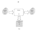
- FIG. 1 is a functional depiction of a conventional duct sensor 100 used to detect smoke within a duct.
- the duct sensor 100 includes a sampling tube 110 , a smoke sensor 120 , and exhaust tube 130 .
- the sampling tube 110 is used to collect the smoke and then to guide the air through the smoke sensor 120 . After passing through the smoke sensor 120 , the air is then released through the exhaust tube 130 . If smoke is detected by the smoke sensor 120 , display 140 indicates the detection of smoke by the duct sensor 100 .
- display 140 indicates the detection of smoke by the duct sensor 100 .
- FIG. 2 illustrates a cross-sectional view of conventional duct sensor 200 attached to duct 240 , the walls of which define duct chamber 240 a .
- Smoke sensor 220 is attached to housing 260 and is located outside of duct 240 .
- Housing 260 is connected to exhaust tube 230 and sampling tube 210 .
- two holes 215 A and 215 B must be formed in a wall of the duct to allow sampling tube 210 and exhaust tube 230 to project into duct chamber 240 a respectively. As such, this requires two holes for every duct sensor that is attached to a portion of the ductwork.
- Sampling tube 210 also includes access holes 250 for capturing air that flows through duct 240 .
- sampling tube 210 must be located upstream of exhaust tube 230 . This means that exhaust tube 230 must be positioned downstream of sampling tube 210 when attaching the duct sensor 200 to the duct system.
- conventional duct sensor 200 must be properly oriented to allow the duct to funnel air in through sampling tube 210 , across sensor 220 via housing 260 , and out through exhaust tube 230 .
- Exemplary embodiments of the present disclosure are directed to a particle detection unit including a detection chamber; a duct detector disposed within the detection chamber, comprising a rod having a first and a second end, the first end distal the second end, a reflector attached to the rod adjacent the first end, and a sensor/emitter device attached to the rod and spaced apart from the reflector at the second end wherein particles disposed between the first and second ends are detected.
- a particle detection unit in another exemplary embodiment, includes a detection chamber; a duct detector disposed at least partially within the detection chamber, and having a sensor attached to an inner wall of the detection chamber. An emitter is attached to the inner wall of the detection chamber opposite the sensor.
- a particle detection unit includes a detection chamber and a duct detector, disposed within the chamber which is defined by a rod having a first and a second end. The first end is distal the second end. An emitter is attached to the rod adjacent the first end, and a sensor is attached to the rod and spaced apart from the reflector.
- a duct detector is installed within a detection chamber defined by a wall having an inner surface.
- the duct detector is attached to the inner surface of the duct and smoke is detected within the chamber.
- the duct detector comprises a rod having a first and a second end. The first end is distal the second end and a reflector is attached to the rod adjacent the first end.
- a sensor and emitter device is attached to the rod and spaced apart from the reflector.
- FIG. 1 is a functional diagram of a conventional duct sensor.
- FIG. 2 is a cross sectional view of a conventional duct sensor attached to a duct.
- FIG. 3 is a cross sectional view of a duct detector in accordance with the present disclosure.
- FIG. 4 is a side view depiction of a duct detector in accordance with the present disclosure.
- FIG. 5 is a side view depiction of a duct detector including a telescoping rod in accordance with the present disclosure.
- FIG. 6 is a side view depiction of a duct detector without a rod in accordance with the present disclosure.
- FIG. 7 a is a side view depiction of a cover in accordance with the present disclosure.
- FIG. 7 b is a front view depiction of a cover in accordance with the present disclosure.
- FIG. 8 is a side view depiction of a duct detector within a tubular rod in accordance with the present disclosure.
- FIG. 3 shows a cross-sectional view of an exemplary duct detector 300 consistent with one embodiment of the present disclosure.
- the duct detector 300 is inserted and attached to an air duct 310 .
- the shape of the duct is defined by the duct walls.
- an improved duct detector is inserted or attached to any chamber or other confined space such as, for exemplary purposes only, ductwork, plenums, air handlers, silos, etc.
- Duct detector 300 includes a rod 320 which has a reflector 330 coupled to the distal end of the rod 320 .
- a sensor and emitter (sensor/emitter) device 340 is spaced apart from the reflector 320 and is also coupled to the rod 320 .
- the sensor and emitter device 340 may contain both a light sensor and emitter.
- the rod 320 including the reflector 330 , and sensor and emitter device 340 is inserted into the chamber of duct 310 .
- a single penetration hole (not shown to scale) may be made in the duct 310 the size of which is dependent on the size of the sensor and emitter device 340 , rod 320 , and reflector 330 .
- the rod may be hollow to accommodate wiring to and from the sensor and emitter device 340 and reflector 330 .
- the rod 320 may then be attached, for example, to the duct 310 by any means known in the art.
- a single penetration hole may be created in the duct 310 housing to accommodate rod 320 , reflector 330 , and sensor and emitter device 340 .
- This embodiment advantageously reduces the number of holes needed in the duct housing as compared to using a conventional duct detector 200 where two holes must be created to allow for sampling tube 210 and exhaust tube 230 to penetrate into the duct as shown in FIG. 2 .
- the sensor/emitter device 340 and the reflector 330 are used to detect particles (i.e., smoke) within the duct.
- the reflector 330 along with the sensor/emitter device 340 use technology that is similar to a beam detector for detecting particles (i.e., smoke) in the air.
- light from the emitter portion of emitter/sensor 340 is transmitted within the duct 310 toward reflector 330 which reflects the light back toward sensor portion of emitter/sensor 340 .
- the sensor portion of emitter/sensor 340 will not receive the same amount of light emitted by the emitter portion of emitter/sensor 340 .
- the percentage of obstructed light is used to determine the presence of unwanted particles (i.e., smoke) between the emitter and the sensor.
- percent obscuration is reported per foot. Thus, if the distance between the emitter and sensor is, for example, 12 inches then the percent obscuration is the real value. However, if the distance between the emitter and sensor is 6 inches, then the percent obscuration is reported as two times the value since the light is only going half the distance.
- the duct detector 300 communicates with alarm indicating devices via control modules and/or control panels through wired or wireless connections 350 which may be, for example, bells, alarms, LED indicators, displays, etc.
- the duct detector 300 uses the duct itself as a chamber for detecting particles (i.e., smoke).
- particles i.e., smoke
- the sensor and emitter device 340 are placed within the duct 310 , thereby eliminating the need to test whether or not air is flowing prior to testing the sensors. In this manner, the need to use airflow and differential pressure devices to detect airflow within the duct 310 prior to the testing is advantageously eliminated.
- the duct detector 300 eliminates the orientation problems described above with respect to conventional smoke detector 200 . More specifically, upstream and downstream orientation concerns regarding sampling tube 210 and exhaust tube 230 are eliminated. The airflow is no longer depended on to guide the smoke out of the duct to the sensor 220 .
- the sensor and emitter device 340 are now located within the duct itself. In addition, the spacing between the sensor/emitter and thus the distance the light travels from the sensor portion of emitter/sensor 340 to reflector 330 and back to the sensor portion of emitter/sensor 340 may be much closer as compared to convention beam detectors.
- Groups of duct detectors may be installed within an air handling systems and wired together along a pair of bidirectional communication lines.
- a group of such devices on a pair of lines is often referred to as a “line of devices.”
- Many lines of devices can connect back to a control panel that controls the operation of an alarm system.
- a line of devices is usually associated with a certain zone of the building and/or a certain type of device.
- one floor of a multi-story building may have duct detectors wired together on a line that connects back to the control panel.
- each duct detector on a line may be individually addressed from the control panel. Addressing individual devices allows a single duct detector to indicate an alarm condition at a specific location on a line, provides selective operation of specific duct detectors, and can also be useful for fault diagnosis and/or individual duct detector testing.
- a self test mode may be used to eliminate the need to perform a smoke test.
- Smoke tests are undesirable because actual smoke is introduced into the duct and forced by the sensor.
- the emitter's light output may be decreased or obstructed by other means to trigger an alarm indicating device.
- One exemplary way to implement a self test mode to test a sensor may be to decrease the light that is emitted by the emitter or reflected by the reflector. Reducing the amount of light received by the sensor simulates the light reduction caused by smoke. Reducing the light received by the sensor may be caused by decreasing the light output of the emitter's LED or by decreasing the reflection characteristics of the reflector. Once, the light output is decreased the sensor may measure the reduction in light and trigger an alarm indicating device as discussed above.
- Another exemplary embodiment used to test a sensor may be to implement a lens or filter to decrease the light that is detected by the sensor.
- the lens or filter may be placed within the light path between the emitter/sensor. By placing the lens or filter within the light path, the light received by the sensor is reduced thereby simulating the obstruction of light caused by smoke.
- the lens or filter may be electro-mechanically inserted into the light path by any means known in the art, such as a relatively small motor.
- self test mode devices such as, the lens, filter, and LED for the light reduction or output of the emitter, may all be controlled remotely from a control panel as described above.
- FIG. 4 shows a cross-sectional view of a duct detector 400 consistent with one embodiment of the present invention.
- the duct detector 400 is inserted and attached to an air duct 410 .
- the duct detector 400 includes a rod 420 and a sensor 430 which is attached to a distal end of the rod as illustrated in FIG. 4 .
- an emitter 440 may be attached to the rod 420 .
- the position of the emitter 440 may be interchanged with the position of the sensor 430 .
- a single penetration hole may be made in the wall of duct 410 .
- the size of the penetration hole may be dependent on the size of the sensor 430 , the emitter 440 , and the rod 420 .
- the sensor 430 and emitter 440 may use technology that is similar to a beam detector for detecting particles (i.e., smoke) in air.
- the spacing between the sensor 430 and the emitter 440 may be used at much closer distances as compared to a beam detector.
- duct detector 400 when the percentage of obscuration passes a predetermined threshold, an alarm is triggered by duct detector 400 .
- duct detector 400 may be in communication with alarm indicating devices or central control panels through wired or wireless connections 450 . Additionally, to trigger an alarm, duct detector 400 may be also be equipped with self test mode devices, as described above with reference to FIG. 3 . This eliminates the need for a smoke test when testing the sensor of duct detector 400 .
- FIG. 5 shows a cross-sectional view of a duct detector 500 consistent with one embodiment of the present invention.
- the duct detector 500 is inserted and attached to an air duct 510 .
- rods 320 and 420 of FIGS. 3 and 4 are substituted by a telescoping rod 520 .
- the use of a telescoping rod 520 may be used to more easily adjust how far rod 520 penetrates the chamber of the duct 510 .
- duct detector 500 may implement a sensor and emitter device 540 along with a reflector 530 as described with relation to FIG. 3 .
- Duct detector 500 may also implement a sensor and emitter configuration as described with relation to FIG. 4 . With either configuration a single penetration hole may be made in the duct 510 prior to inserting duct detector 500 into air duct 510 . The size of the penetration hole may be dependent on the size of the duct detector 500 . The telescoping rod 520 may then be substantially attached, for example, to the wall of the duct 510 by any means known in the art.
- duct detector 500 when the percentage of obscuration passes a predetermined threshold, an alarm indicating such may be triggered by duct detector 500 .
- duct detector 500 may be in communication with alarm indicating devices or central control panels through wired or wireless connections 550 . Additionally, to trigger an alarm, duct detector 500 may also be equipped with self test mode devices, as described above with reference to FIG. 3 . This eliminates the need for a smoke test when testing the sensor of duct detector 500 .
- FIG. 6 illustrates a cross-sectional view of a duct detector consistent with one embodiment of the present invention.
- the duct detector 600 is substantially inserted and attached to opposing walls of air duct 610 .
- rods 320 and 420 of FIGS. 3 and 4 respectively, are removed.
- duct detector 600 may implement a sensor and emitter device 640 along with a reflector 630 as described with relation to FIG. 3 .
- sensor and emitter device 640 is attached to a wall of the duct 610 substantially opposite reflector 630 .
- Duct detector 600 may also attach a sensor to the wall of the duct 610 substantially opposite an emitter. Any means known in the art may be used to attach the sensor and emitter device 640 , reflector 630 , emitter, or sensor to the wall of the duct and may be dependent on the size of the sensor and emitter device 640 , reflector 630 , emitter, or sensor used for the duct detector 600 .
- duct detector 600 when the percentage of obstruction passes a predetermined threshold an alarm indicating such may be triggered by duct detector 600 .
- duct detector 600 may be in communication with alarm indicating devices or central control panels through wired or wireless connections 650 . Additionally, to trigger an alarm, duct detector 600 may be also be equipped with self test mode devices, as described above with reference to FIG. 3 . This eliminating the need for a smoke test when testing the sensor of duct detector 600 .
- FIGS. 7 a and 7 b illustrate one exemplary embodiment of a cover 700 .
- FIG. 7 a depicts a side view of the cover 700 and
- FIG. 7 b depicts a front view of cover 700 .
- the cover 700 may be coupled to a rod, telescoping rod, duct wall, sensor/emitter device, sensor, emitter, or reflector.
- the cover may be used to substantially prevent particles (i.e., dust) from accumulating on a sensor and emitter device, reflector, sensor, and emitter. Whatever shape used, the cover 700 substantially prevents dust accumulation while still allowing the emitter, sensor, and reflector to emit, sense, and reflect light 710 , respectively. By covering the above mentioned structures, particles such as dust may be substantially prevented from overwhelming the structures.
- the duct detector may substantially maintain its accuracy for detecting smoke for longer periods of time.
- FIG. 8 shows a side view of a duct detector 800 consistent with one embodiment of the present invention.
- the duct detector 800 is substantially inserted and attached to an air duct 810 .
- rods 320 and 420 of FIGS. 3 and 4 are substituted by a substantially tubular rod 820 .
- the use of a tubular rod 820 may be used to protect the sensor and emitter device, sensor, emitter, or reflector while allowing smoke or other particles to travel through ventilation structures 830 .
- the particles may pass through the tubular rod 820 and in between the sensor and emitter device and reflector.
- the duct detector 800 may also implement a sensor and emitter within the tubular rod 820 . The sensor located within the tubular rod 820 across from the emitter which may also be located substantially within the tubular rod 820 .
- ventilation structures 830 may be used to allow particles (i.e., smoke) to pass through the tubular rod 820 and enter the line of site between the emitter and sensor.
- particles i.e., smoke
- a single penetration hole may be made in the duct 810 prior to inserting duct detector 800 into air duct 810 .
- the size of the penetration hole may be dependent on the size of the duct detector 800 .
- the tubular rod 820 may then be substantially attached, for example, to the wall of the duct 810 by any means known in the art.
- duct detector 800 when the percentage of obstruction passes a predetermined threshold, an alarm indicating such may be triggered by duct detector 800 .
- duct detector 800 may be in communication with alarm indicating devices or central control panels through wired or wireless connections 850 . Additionally, to trigger an alarm, duct detector 800 may be also be equipped with self test mode devices, as described above with reference to FIG. 3 . This eliminates the need for a smoke test when testing the sensor of duct detector 800 .
- the improved duct detector disclosed herein advantageously reduces the number of holes required to install a duct detector within a duct system. In fact, only one installation hole may be created within the duct per at least one duct detector that is to be installed within a duct.
- the improved duct detector disclosed herein advantageously uses the duct itself as a chamber for detecting particles (i.e., smoke) which obviates the need to use airflow and differential pressure devices. Thus, there is no longer a need to confirm the presence of airflow before testing the operability of the duct detectors. Likewise, upstream and downstream orientation concerns regarding exhaust tubes and sampling tubes are eliminated by implementing the improved duct detector. Furthermore, the improved duct detector allows for self testing with a self test mode. Consequently, the improved duct detector reduces the labor costs and hazards associated with manufacturing, installing, and testing duct detectors.
Landscapes
- Physics & Mathematics (AREA)
- Health & Medical Sciences (AREA)
- Life Sciences & Earth Sciences (AREA)
- Chemical & Material Sciences (AREA)
- Analytical Chemistry (AREA)
- Biochemistry (AREA)
- General Health & Medical Sciences (AREA)
- General Physics & Mathematics (AREA)
- Immunology (AREA)
- Pathology (AREA)
- Fire-Detection Mechanisms (AREA)
- Investigating Or Analysing Materials By Optical Means (AREA)
- Fire Alarms (AREA)
Abstract
Description
Claims (14)
Priority Applications (1)
| Application Number | Priority Date | Filing Date | Title |
|---|---|---|---|
| US12/946,708 US8705038B2 (en) | 2010-11-15 | 2010-11-15 | Duct detector |
Applications Claiming Priority (1)
| Application Number | Priority Date | Filing Date | Title |
|---|---|---|---|
| US12/946,708 US8705038B2 (en) | 2010-11-15 | 2010-11-15 | Duct detector |
Publications (2)
| Publication Number | Publication Date |
|---|---|
| US20120120399A1 US20120120399A1 (en) | 2012-05-17 |
| US8705038B2 true US8705038B2 (en) | 2014-04-22 |
Family
ID=46047481
Family Applications (1)
| Application Number | Title | Priority Date | Filing Date |
|---|---|---|---|
| US12/946,708 Active 2031-07-21 US8705038B2 (en) | 2010-11-15 | 2010-11-15 | Duct detector |
Country Status (1)
| Country | Link |
|---|---|
| US (1) | US8705038B2 (en) |
Cited By (1)
| Publication number | Priority date | Publication date | Assignee | Title |
|---|---|---|---|---|
| US11493229B2 (en) | 2019-03-20 | 2022-11-08 | Carrier Corporation | Chamberless wide area duct smoke detector |
Families Citing this family (1)
| Publication number | Priority date | Publication date | Assignee | Title |
|---|---|---|---|---|
| US12007133B2 (en) * | 2017-06-29 | 2024-06-11 | American Air Filter Company, Inc. | Sensor array environment for an air handling unit |
Citations (12)
| Publication number | Priority date | Publication date | Assignee | Title |
|---|---|---|---|---|
| US3600590A (en) * | 1968-11-12 | 1971-08-17 | Harry Einstein | Gas measuring apparatus for detecting contaminants |
| US3796887A (en) * | 1972-05-17 | 1974-03-12 | Itt | Photometric analyzer |
| US4069711A (en) * | 1973-05-15 | 1978-01-24 | Bayer Aktiengesellschaft | Method and apparatus for measuring the grain-size of fine powders |
| US4560873A (en) * | 1983-06-17 | 1985-12-24 | Lear Siegler, Inc. | Situ multi-channel combustion gas analyzer |
| US4651004A (en) * | 1984-04-28 | 1987-03-17 | Fuji Electric Corporate Research And Development Co., Ltd. | Optical gas densitometer |
| US5089000A (en) * | 1987-09-18 | 1992-02-18 | John M. Agee | Surgical method and instrument therefor |
| US5170064A (en) * | 1989-09-29 | 1992-12-08 | Atomic Energy Of Canada Limited | Infrared-based gas detector using a cavity having elliptical reflecting surface |
| US5636918A (en) * | 1996-08-30 | 1997-06-10 | Lott; Jeffrey M. | Precision sighting instrument for viewing obstructed areas |
| US6193386B1 (en) * | 1998-08-24 | 2001-02-27 | Carica Usa, Inc. | Illuminated telescopic inspection/pickup tool |
| US20050119670A1 (en) * | 2002-03-01 | 2005-06-02 | Stephen Kerr | Puncture site closure device |
| US6943885B2 (en) * | 2000-04-27 | 2005-09-13 | Senseair Ab | Gas cell adapted for carbon dioxide |
| US7909520B2 (en) * | 2005-02-16 | 2011-03-22 | Jonathan Barabė | Telescopic viewing device |
-
2010
- 2010-11-15 US US12/946,708 patent/US8705038B2/en active Active
Patent Citations (12)
| Publication number | Priority date | Publication date | Assignee | Title |
|---|---|---|---|---|
| US3600590A (en) * | 1968-11-12 | 1971-08-17 | Harry Einstein | Gas measuring apparatus for detecting contaminants |
| US3796887A (en) * | 1972-05-17 | 1974-03-12 | Itt | Photometric analyzer |
| US4069711A (en) * | 1973-05-15 | 1978-01-24 | Bayer Aktiengesellschaft | Method and apparatus for measuring the grain-size of fine powders |
| US4560873A (en) * | 1983-06-17 | 1985-12-24 | Lear Siegler, Inc. | Situ multi-channel combustion gas analyzer |
| US4651004A (en) * | 1984-04-28 | 1987-03-17 | Fuji Electric Corporate Research And Development Co., Ltd. | Optical gas densitometer |
| US5089000A (en) * | 1987-09-18 | 1992-02-18 | John M. Agee | Surgical method and instrument therefor |
| US5170064A (en) * | 1989-09-29 | 1992-12-08 | Atomic Energy Of Canada Limited | Infrared-based gas detector using a cavity having elliptical reflecting surface |
| US5636918A (en) * | 1996-08-30 | 1997-06-10 | Lott; Jeffrey M. | Precision sighting instrument for viewing obstructed areas |
| US6193386B1 (en) * | 1998-08-24 | 2001-02-27 | Carica Usa, Inc. | Illuminated telescopic inspection/pickup tool |
| US6943885B2 (en) * | 2000-04-27 | 2005-09-13 | Senseair Ab | Gas cell adapted for carbon dioxide |
| US20050119670A1 (en) * | 2002-03-01 | 2005-06-02 | Stephen Kerr | Puncture site closure device |
| US7909520B2 (en) * | 2005-02-16 | 2011-03-22 | Jonathan Barabė | Telescopic viewing device |
Cited By (2)
| Publication number | Priority date | Publication date | Assignee | Title |
|---|---|---|---|---|
| US11493229B2 (en) | 2019-03-20 | 2022-11-08 | Carrier Corporation | Chamberless wide area duct smoke detector |
| US12298027B2 (en) | 2019-03-20 | 2025-05-13 | Carrier Corporation | Chamberless wide area duct smoke detector |
Also Published As
| Publication number | Publication date |
|---|---|
| US20120120399A1 (en) | 2012-05-17 |
Similar Documents
| Publication | Publication Date | Title |
|---|---|---|
| KR100906206B1 (en) | Method and device for identifying and localising a fire | |
| US9384643B2 (en) | Fire detection | |
| US9459208B2 (en) | Duct detector with remote airflow test capability | |
| EP3134886B1 (en) | Self-testing smoke detector with integrated smoke source | |
| TWI684754B (en) | Improvements to aspirated sampling systems | |
| US8294587B2 (en) | Smoke detector and method of checking blockage of its smoke holes | |
| WO2016116024A1 (en) | Point-type active smoke detector with or without gas sampling tube and air sampling system | |
| CN105917208A (en) | Respiratory particle detection with different flow modifications | |
| US8939013B2 (en) | Duct detector with improved functional test capability | |
| ES2958969T3 (en) | Leak detection in an aspiration fire detection system | |
| AU2017202317A1 (en) | Sampling point for a particle detector | |
| US8705038B2 (en) | Duct detector | |
| AU2013101580A4 (en) | Ventilation system | |
| KR102295285B1 (en) | Device for testing fire sensor assembly | |
| US11189143B2 (en) | Aspiration smoke detection system | |
| HK1084765B (en) | Method and device for identifying and localising a fire | |
| HK1228497A1 (en) | Improvements to aspirated sampling systems |
Legal Events
| Date | Code | Title | Description |
|---|---|---|---|
| AS | Assignment |
Owner name: SIMPLEXGRINNELL LP, MASSACHUSETTS Free format text: ASSIGNMENT OF ASSIGNORS INTEREST;ASSIGNORS:FARLEY, DANIEL G.;CAPOWSKI, ANTHONY J.;REEL/FRAME:025364/0831 Effective date: 20101115 |
|
| AS | Assignment |
Owner name: TYCO FIRE & SECURITY GMBH, SWITZERLAND Free format text: ASSIGNMENT OF ASSIGNORS INTEREST;ASSIGNOR:SIMPLEXGRINNELL LP;REEL/FRAME:032229/0201 Effective date: 20131120 |
|
| STCF | Information on status: patent grant |
Free format text: PATENTED CASE |
|
| MAFP | Maintenance fee payment |
Free format text: PAYMENT OF MAINTENANCE FEE, 4TH YEAR, LARGE ENTITY (ORIGINAL EVENT CODE: M1551) Year of fee payment: 4 |
|
| AS | Assignment |
Owner name: JOHNSON CONTROLS FIRE PROTECTION LP, FLORIDA Free format text: ASSIGNMENT OF ASSIGNORS INTEREST;ASSIGNOR:TYCO FIRE & SECURITY GMBH;REEL/FRAME:049671/0756 Effective date: 20180927 |
|
| MAFP | Maintenance fee payment |
Free format text: PAYMENT OF MAINTENANCE FEE, 8TH YEAR, LARGE ENTITY (ORIGINAL EVENT CODE: M1552); ENTITY STATUS OF PATENT OWNER: LARGE ENTITY Year of fee payment: 8 |
|
| AS | Assignment |
Owner name: JOHNSON CONTROLS US HOLDINGS LLC, WISCONSIN Free format text: ASSIGNMENT OF ASSIGNORS INTEREST;ASSIGNOR:JOHNSON CONTROLS FIRE PROTECTION LP;REEL/FRAME:058599/0339 Effective date: 20210617 Owner name: JOHNSON CONTROLS TYCO IP HOLDINGS LLP, WISCONSIN Free format text: ASSIGNMENT OF ASSIGNORS INTEREST;ASSIGNOR:JOHNSON CONTROLS INC;REEL/FRAME:058600/0047 Effective date: 20210617 Owner name: JOHNSON CONTROLS INC, WISCONSIN Free format text: ASSIGNMENT OF ASSIGNORS INTEREST;ASSIGNOR:JOHNSON CONTROLS US HOLDINGS LLC;REEL/FRAME:058599/0922 Effective date: 20210617 |
|
| AS | Assignment |
Owner name: TYCO FIRE & SECURITY GMBH, SWITZERLAND Free format text: ASSIGNMENT OF ASSIGNORS INTEREST;ASSIGNOR:JOHNSON CONTROLS TYCO IP HOLDINGS LLP;REEL/FRAME:066740/0208 Effective date: 20240201 Owner name: TYCO FIRE & SECURITY GMBH, SWITZERLAND Free format text: ASSIGNMENT OF ASSIGNOR'S INTEREST;ASSIGNOR:JOHNSON CONTROLS TYCO IP HOLDINGS LLP;REEL/FRAME:066740/0208 Effective date: 20240201 |
|
| MAFP | Maintenance fee payment |
Free format text: PAYMENT OF MAINTENANCE FEE, 12TH YEAR, LARGE ENTITY (ORIGINAL EVENT CODE: M1553); ENTITY STATUS OF PATENT OWNER: LARGE ENTITY Year of fee payment: 12 |