US8704574B2 - SSPC distribution system and control strategy - Google Patents
SSPC distribution system and control strategy Download PDFInfo
- Publication number
- US8704574B2 US8704574B2 US13/372,282 US201213372282A US8704574B2 US 8704574 B2 US8704574 B2 US 8704574B2 US 201213372282 A US201213372282 A US 201213372282A US 8704574 B2 US8704574 B2 US 8704574B2
- Authority
- US
- United States
- Prior art keywords
- dsp
- sspc
- slave
- slave dsp
- master
- Prior art date
- Legal status (The legal status is an assumption and is not a legal conclusion. Google has not performed a legal analysis and makes no representation as to the accuracy of the status listed.)
- Expired - Fee Related, expires
Links
Images



Classifications
-
- H—ELECTRICITY
- H02—GENERATION; CONVERSION OR DISTRIBUTION OF ELECTRIC POWER
- H02J—ELECTRIC POWER NETWORKS; CIRCUIT ARRANGEMENTS OR SYSTEMS FOR SUPPLYING OR DISTRIBUTING ELECTRIC POWER; SYSTEMS FOR STORING ELECTRIC ENERGY
- H02J1/00—Circuit arrangements for DC mains or DC distribution networks
- H02J1/08—Three-wire DC power distribution systems; Systems having more than three wires
-
- H—ELECTRICITY
- H02—GENERATION; CONVERSION OR DISTRIBUTION OF ELECTRIC POWER
- H02J—ELECTRIC POWER NETWORKS; CIRCUIT ARRANGEMENTS OR SYSTEMS FOR SUPPLYING OR DISTRIBUTING ELECTRIC POWER; SYSTEMS FOR STORING ELECTRIC ENERGY
- H02J13/00—Circuit arrangements for providing remote monitoring or remote control of equipment in a power distribution network
- H02J13/18—Circuit arrangements for providing remote monitoring or remote control of equipment in a power distribution network characterised by the remotely-controlled equipment, e.g. converters or transformers
- H02J13/34—Circuit arrangements for providing remote monitoring or remote control of equipment in a power distribution network characterised by the remotely-controlled equipment, e.g. converters or transformers the equipment being switches, relays or circuit breakers
-
- H—ELECTRICITY
- H02—GENERATION; CONVERSION OR DISTRIBUTION OF ELECTRIC POWER
- H02J—ELECTRIC POWER NETWORKS; CIRCUIT ARRANGEMENTS OR SYSTEMS FOR SUPPLYING OR DISTRIBUTING ELECTRIC POWER; SYSTEMS FOR STORING ELECTRIC ENERGY
- H02J2105/00—Networks for supplying or distributing electric power characterised by their spatial reach or by the load
- H02J2105/30—Networks for supplying or distributing electric power characterised by their spatial reach or by the load the load networks being external to vehicles, i.e. exchanging power with vehicles
- H02J2105/32—Networks for supplying or distributing electric power characterised by their spatial reach or by the load the load networks being external to vehicles, i.e. exchanging power with vehicles for aircrafts
Definitions
- the present invention generally relates to power distribution systems and more particularly, a solid state power controller (SSPC) distribution system (i.e. a line replaceable module, or a circuit card) and control strategy.
- SSPC solid state power controller
- Power distribution systems typically employ a switching mechanism to supply power to various loads in an aircraft.
- a single load is associated with a single distribution channel and a dedicated switching mechanism is employed per channel to provide the power needs as required.
- the SSPC is one such switching mechanism employed in aircraft systems to distribute electric power among various loads.
- MTBF mean time between failures
- a solid state power controller (SSPC) system comprises a plurality of SSPC channels configured to provide power distribution functions; a master digital signal processor (DSP); a first slave DSP connected to the master DSP; a second slave DSP connected to the master DSP, wherein each of the plurality of SSPC channels are connected to both the first slave DSP and second slave DSP.
- DSP digital signal processor
- a solid state power controller (SSPC) system comprises a plurality of SSPC channels configured to provide power distribution functions; a master digital signal processor (DSP); a first power source connected to the master DSP; a first slave DSP connected to the master DSP; a second slave DSP connected to the master DSP, wherein each of the plurality of SSPC channels are connected to both the first slave DSP and second slave DSP; a second power source isolated from the first power source; and a third power source shared by the plurality of SSPC channels.
- DSP digital signal processor
- a method of providing power distribution functions in a line replaceable module includes providing control commands from a master digital signal processor (DSP) to a pair of slave DSP in a power distribution system; and controlling power distribution functions distributed through a plurality of solid state power channels (SSPC) using the pair of slave DSP wherein the pair of slave DSP are both connected to each channel in the plurality of SSPC channels.
- DSP master digital signal processor
- SSPC solid state power channels
- FIG. 1 is a schematic diagram of a power distribution system in accordance with an aspect of the subject technology
- FIG. 2 is a block diagram of a power distribution system in accordance with an exemplary embodiment of the present invention
- FIG. 3 is a schematic diagram of a power control strategy employed in the power distribution system of FIG. 2 in accordance with an exemplary embodiment of the present invention.
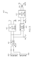
- FIG. 4 is a schematic diagram of an exemplary SSPC channel of the power distribution system of FIG. 2 showing gate driving and current sensing strategies in accordance with an exemplary embodiment of the present invention
- the present invention generally provides a power distribution system and method. Aspects of the subject technology may be useful, for example, in aircraft based control systems where space and weight factors may be at a premium.
- an aircraft power distribution system may comprise a number of power distribution units (PDUs) (not shown), each further comprising several SSPC line replaceable modules (LRMs) 100 .
- Each SSPC LRM 100 may comprise multiple SSPC channels 110 .
- a typical SSPC channel 110 may include a solid state switching device (SSSD) 120 , which performs the fundamental power on/off switching, and an SSPC processing engine 130 dedicated to the channel, which is responsible for SSSD on/off control and feeder wire protection.
- the SSPC processing engine 130 can be built by either programmable devices, such as micro-controllers, DSPs, field programmable gate arrays (FPGAs), discrete analog and digital circuitry, or application specific integrated circuits (ASICs).
- the control of the SSSD 120 through the SSPC processing engine 130 is usually configured as the “high side” drive with an isolated control power supply reference to the source terminal of for example, a MOSFET to provide required gate drive power.
- the SSPC processing engine 130 may also be placed on the “high side” for load current sensing and processing, as well as data communication between the SSPC channel and the LRM level controller.
- the number of isolated power supplies and SSPC processing engines increases as more SSPC channels are required to be implemented on a LRM 100 .
- more advanced power distribution functions may be needed in the system such as arc fault detection (AFD), electric load fault diagnostics, and prognostics, etc.
- AFD arc fault detection
- Increasing the amount of SSPC channels may increase the power dissipation of the LRM 100 , which can negatively impact the mean time between failures (MTBF) of the LRM 100 .
- More SSPC channels 110 may also take up significant board area, which limits the number of SSPC channels that can be incorporated making the board layout more difficult.
- FIG. 2 shows the SSPC distribution system 200 in a block diagram showing components in electrical communication.
- the SSPC distribution system 200 may be embodied as an LRM and referred to interchangeably as the LRM 200 .
- Each LRM 200 may include three digital signal processors, a master DSP 210 , a slave DSP 215 , and a slave DSP 220 and logic circuitry, which may be referred to as an arbitration logic module 225 . It will be understood that the logic circuitry may not necessarily be a programmable device.
- the master DSP 210 is in communication with the slave DSP 215 and slave DSP 220 .
- the slave DSP 215 may be in communication with the slave DSP 220 .
- the arbitration logic module 235 may be in communication with the master DSP 210 , the slave DSP 215 , and the slave DSP 220 .
- the communication between the master DSP 210 , the slave DSP 215 , the slave DSP 220 , and the arbitration logic module 225 may be commutative.
- a voltage signal processing unit 275 may be connected to the master DSP 210 .
- the LRM 200 may also include a plurality of SSPC channels 250 . . . 250 n .
- the SSPC channels 250 . . . 250 n may be referred to as SSPC channels 250 .
- Each of the SSPC channels 250 may be connected to the slave DSP 215 and the slave DSP 220 simultaneously.
- Each of the SSPC channels 250 may include a MOSFET gate driver 255 .
- a current signal processing unit 270 may be in communication with each of the SSPC channels 250 and the slave DSP 220 .
- the current signal processing unit 270 may be configured to receive a current sensing signal from respective SSPC channels 250 for processing the management of power back to respective SSPC channels 250 .
- An isolation boundary 280 may electrically isolate the master DSP 210 from the slave DSP 215 , slave DSP 220 , the arbitration logic module 225 , and the SSPC channels 250 .
- a transceiver 230 and a transceiver 235 may be connected to a dual redundant data bus 265 .
- the transceiver 230 may be in communication with the master DSP 210 .
- the transceiver 235 may be in communication with the slave DSP 220 .
- the master DSP 210 may be designated as a LRM 200 supervisor and may be configured for communication through serial communication interfaces (such as ARINC429 and CAN, etc.) with external control equipment.
- the master DSP 210 may also be configured to perform general housekeeping tasks, SSPC load configuration controls, and periodic built-in-test (BIT) for the LRM 200 .
- the master DSP 210 may interface to a test data bus (e.g. RS-422), which may facilitate operating software and configuration data loading, software testing and debugging.
- the master DSP 210 may also be configured with programming capable of managing the responsibilities of the slave DSP 215 and slave DSP 220 .
- the slave DSP 215 and slave DSP 220 may be configured to perform SSPC channel controls including load status monitoring and feeder wire protections, etc.
- the responsibilities of the slave DSP 215 and the slave DSP 220 may be partitioned for efficient control of the SSPC channels 250 .
- slave DSP 215 may be configured for example, to manage power commutation, over-current protection, and parallel arc fault detection.
- the slave DSP 220 may be configured, for example, to monitor load current and series arc fault detection.
- the gains of current sensing signals feeding to the slave DSP 215 and to slave DSP 220 through current signal processing unit 270 may be selected differently to achieve optimal SSPC performance.
- the current level for normal load current monitoring and series arc fault detection may usually be around and below the nominal value of the SSPC channel rating.
- the current level for wire protection and parallel arc fault detection may usually be much higher than the nominal value of the SSPC channel rating.
- the LRM 200 may be configured to provide fundamental redundancy controls in case any one of the master DSP 210 , slave DSP 215 , or slave DSP 220 fails to operate properly.
- the responsibilities of slave DSP 215 and slave DSP 220 may be either partially or wholly interchangeable between the two.
- Operational software facilitating each individual DSP function may be allocated on both slave DSP 215 and slave DSP 220 with options to select any or all portions of the software to run on any one of the slave DSPs 215 ; 220 .
- the arbitration between the master DSP 210 and slave DSPs 215 ; 220 may be realized by the arbitration logic module 225 , along with digital buffers 240 .
- the slave DSP 215 and the slave DSP 220 may be isolated from the gate driver circuitry within the SSPC channels 250 by the buffers 240 .
- the system 200 may employ three buffers 240 .
- the three buffers 240 shown are designated as buffer #1, buffer #2, and buffer #3.
- buffer #2 may be designated to store the pre-loaded SSPC channel on/off states, which may be enabled when both slave DSPs ( 215 ; 220 ) fail to operate properly, so that all SSPC channels on the LRM 200 can be in their fail-safe states.
- buffer #2 may be loaded with data by Slave DSP 215 immediately after the slave DSP 215 completes its power up reset. In the event both the slave DSP 215 and slave DSP 220 fail to operate properly, only buffer #2, which may contain the pre-loaded SSPC channel on/off states, will be enabled, so that all SSPC channels 250 will be in their fail-safe states.
- only buffer #1 may be enabled by the arbitration logic module 225 , so that slave DSP 215 has the control over all SSPC channels 250 .
- buffer #2 and buffer #3 may be disabled.
- an abnormality for example, an operating software malfunction that results in for example, a “no proper response” message to the arbitration logic module 225
- only buffer #3 will be enabled, to allow the slave DSP 220 to take over the control of all SSPC channels 250 .
- the transceiver 230 that may be enabled by default, may be disabled, and transceiver 235 , that may be disabled by default, may be enabled, so that the slave DSP 220 can take over the communication function between the LRM 200 and the external control equipment (not shown).
- voltage monitoring functions from the voltage signal processing unit 275 which may not be considered critical for SSPC operations, may be lost.
- the slave DSP 215 may “switch on” the part of the software designated to the slave DSP 220 to perform functions for both the slave DSP 215 and slave DSP 220 . There may be potentially degraded performance of the slave DSP 220 functions as a result of non-optimized current sensing gain configured for the optimal performance of the slave DSP 215 .
- Power to the master DSP 210 , the slave DSP 215 , slave DSP 220 , the arbitration logic module 225 , the buffers 240 , the SSPC channels 250 , the current signal processing unit 270 , and the voltage signal processing unit 275 may be derived from a main power input bus 260 .
- the main power input bus 260 may be, for example, a 28V bus.
- a back-up power source 490 for example a 28VDC source (diode ORed from the main power input bus 260 ) may also provide power to the system 200 when needed.
- Power from the main power input bus 260 and the back-up power source 490 may be filtered through an EMI filter 410 .
- voltage conversion for example, a step-down conversion to 28VDC, may be done for the main power input bus 260 before being diode ORed with the back-up power source 490 .
- a power supply scheme 400 may provide separate but minimal power supply sources for different sections of the system 200 .
- only three control power supplies, (V M , V S , and V 15V ) may be needed to provide the control needs for the entire SSPC distribution system 200 .
- an isolated DC-DC converter 420 may be connected to the EMI filter 410 configured to provide the V S power supply.
- V S may be an isolated power source, supplied by the main power input bus 260 .
- V S may be disposed to power the slave DSP 215 , the slave DSP 220 , (and associated digital circuitry) the buffers 240 , and the current signal processing unit 270 .
- a non-isolated DC-DC converter 440 may be connected to the EMI filter 410 configured to provide the V M power supply.
- V M may be a non-isolated control power source, supplied by the main power input bus 260 .
- V M may be disposed to generate power to the master DSP 210 , transceivers 230 ; 235 , and the voltage signal processing unit 275 .
- Another isolated DC-DC converter 430 may be connected to the non-isolated DC-DC converter 440 and a transformer 450 configured to provide the V 15V power supply.
- V 15V may be an isolated power source disposed to provide the necessary isolated power for the MOSFET gate drives of all SSPC channels 250 .
- a single power source V 15V can be employed to power multiple SSPC channels 250 . It will be understood that the power needed to drive the SSPC channels 250 may vary depending on the loads and the choice of isolated DC-DC converter 430 and transformer 450 may thus vary with the needs of the SSPC channels 250 .
- the SSPC channel 250 may include exemplary current sensing and gate drive strategies.
- the SSPC channel 250 may include a MOSFET gate driver 255 , a MOSFET 540 (e.g. Linear Technology's LTC4440), a linear and low dropout regulator (LDO) 580 , and a diode 515 , configured to control the independent power needs from each SSPC channel 250 to respective loads.
- a current sensing section 502 may include a shunt resistor 550 , a differential amplifier 560 , and an inductor 570 .
- the amplifier 560 may be, for example, an op-amp or a current shunt monitor integrated circuit.
- the inductor 570 may use, for example, a ferrite core.
- a gate drive ground 520 may be common to all the SSPC channels 250 .
- the shunt resistor 550 is connected to the amplifier 560 and between the main power input bus 260 and the drain of the MOSFET 540 .
- the shunt resistor 550 may have a very low resistance value.
- the voltage across the resistor 550 may provide how much current is passing through the MOSFET 540 .
- the amplifier 560 may be configured to amplify the signal passing through the resistor 550 .
- the amplified signal may thus be passed on to the current signal processing unit 270 and the slave DSP 220 ( FIG. 2 ).
- each SSPC channel 250 may share a common ground reference (D GND ).
- a single power source V S may be employed to power each of the amplifiers 560 of respective SSPC channels 250 when using the common ground reference (D GND ) while managing voltage control of the MOSFET 540 as measured across the resistor 550 .
- the use of the inductor 570 connected between the main power input bus 260 and the common ground (D GND ) may provide EMI control.
- the V 15V power supply may be connected in common with each SSPC channels 250 as discussed previously.
- the LDO 580 may be connected between the source of the V 15V power supply, the gate driver 255 , and the diode 515 .
- the LDO 580 may ensure that the gate to source voltage of the MOSFETs 540 of respective SSPC channels 250 never exceeds a safe voltage level under all SSPC operating conditions. For example, when a particular SSPC channel 250 is switched off, the voltage from any other SSPC channel 250 on the line may be regulated by the LDO 580 so that a safe voltage is encountered by the gate driver 255 and the MOSFET 540 .
- the diode 515 ensures no interaction between SSPC channels 250 through its reverse voltage blocking capability while still allowing the common power supply V 15V to provide the valid and required gate drive power for the associated particular SSPC channel.
- the diode 515 may be rated to withstand the highest possible voltage difference between any two SSPC channels 250 .
Landscapes
- Engineering & Computer Science (AREA)
- Power Engineering (AREA)
- Power Sources (AREA)
- Power Conversion In General (AREA)
Abstract
Description
Claims (14)
Priority Applications (2)
| Application Number | Priority Date | Filing Date | Title |
|---|---|---|---|
| US13/372,282 US8704574B2 (en) | 2012-02-13 | 2012-02-13 | SSPC distribution system and control strategy |
| EP13153152.7A EP2626973B1 (en) | 2012-02-13 | 2013-01-29 | SSPC distribution system and control strategy |
Applications Claiming Priority (1)
| Application Number | Priority Date | Filing Date | Title |
|---|---|---|---|
| US13/372,282 US8704574B2 (en) | 2012-02-13 | 2012-02-13 | SSPC distribution system and control strategy |
Publications (2)
| Publication Number | Publication Date |
|---|---|
| US20130207705A1 US20130207705A1 (en) | 2013-08-15 |
| US8704574B2 true US8704574B2 (en) | 2014-04-22 |
Family
ID=47678598
Family Applications (1)
| Application Number | Title | Priority Date | Filing Date |
|---|---|---|---|
| US13/372,282 Expired - Fee Related US8704574B2 (en) | 2012-02-13 | 2012-02-13 | SSPC distribution system and control strategy |
Country Status (2)
| Country | Link |
|---|---|
| US (1) | US8704574B2 (en) |
| EP (1) | EP2626973B1 (en) |
Cited By (12)
| Publication number | Priority date | Publication date | Assignee | Title |
|---|---|---|---|---|
| US20160156194A1 (en) * | 2014-12-01 | 2016-06-02 | Hamilton Sundstrand Corporation | Virtual channel abstraction layer for solid state power controls |
| US10033378B2 (en) | 2015-12-22 | 2018-07-24 | Rolls-Royce Plc | Apparatus and method for solid state power control of current load |
| US10234829B2 (en) | 2015-05-07 | 2019-03-19 | Hamilton Sundstrand Corporation | Multi-channel current balancing system including parallel solid-state power controllers |
| US10277037B2 (en) | 2015-12-04 | 2019-04-30 | Hs Elektronik Systeme Gmbh | Power distribution system |
| DE102017127983A1 (en) * | 2017-11-27 | 2019-05-29 | Beckhoff Automation Gmbh | FUSE MODULE AND FIELD BUS SYSTEM WITH FUSE MODULE |
| US10329032B2 (en) | 2015-12-04 | 2019-06-25 | Hs Elektronik Systeme Gmbh | Power management and distribution system |
| US10476264B2 (en) | 2015-11-18 | 2019-11-12 | General Electric Company | System and method for fault ride through |
| US10770896B2 (en) * | 2015-12-11 | 2020-09-08 | Hs Elektronik Systeme Gmbh | Solid state power controller |
| US10923920B2 (en) | 2017-04-11 | 2021-02-16 | Hs Elektronik System Gmbh | Solid state power controller |
| US11005254B2 (en) | 2016-11-18 | 2021-05-11 | Ge Aviation Systems Limited | System and method for protecting a solid-state power controller |
| US11424642B2 (en) | 2019-03-22 | 2022-08-23 | Hamilton Sundstrand Corporation | Solid switch power distribution controller with storage device backup |
| US12271172B2 (en) | 2021-12-07 | 2025-04-08 | Hamilton Sundstrand Corporation | Solid state power controllers |
Families Citing this family (9)
| Publication number | Priority date | Publication date | Assignee | Title |
|---|---|---|---|---|
| EP2945244B1 (en) * | 2014-05-15 | 2022-07-06 | Airbus Operations GmbH | Power and data distribution module and method for power and data distribution in an airborne vehicle |
| US10642229B2 (en) * | 2014-07-22 | 2020-05-05 | Hamilton Sundstrand Corporation | Coordination of variable groupings of control channels |
| FR3024925B1 (en) * | 2014-08-14 | 2016-08-26 | Zodiac Aero Electric | SYSTEM AND METHOD FOR CONTROLLING AT LEAST ONE POWER MEMBER, IN PARTICULAR FOR AN AIRCRAFT |
| US10048997B2 (en) * | 2016-05-04 | 2018-08-14 | Hamilton Sundstrand Corporation | Single event latch up mitigation in solid state power controllers |
| CN105959194A (en) * | 2016-06-16 | 2016-09-21 | 成都易云知科技有限公司 | DSP-based electronic communication system |
| FR3054739B1 (en) * | 2016-07-27 | 2020-06-19 | Zodiac Aero Electric | PILOTAGE ASSEMBLY OF STATIC SWITCHING ELEMENTS IN AN AIRCRAFT |
| CN108539855B (en) * | 2018-04-13 | 2020-08-04 | 上海广吉电气有限公司 | High-speed DSP control power grid intelligent monitoring voltage regulation compensation and protection control system |
| WO2022110096A1 (en) | 2020-11-30 | 2022-06-02 | 华为数字能源技术有限公司 | Bipolar photovoltaic system, power supply system and redundancy protection method |
| CN116317491B (en) * | 2023-03-24 | 2026-07-17 | 核工业西南物理研究院 | Control system and control method for 10 MW-level high-voltage power supply |
Citations (8)
| Publication number | Priority date | Publication date | Assignee | Title |
|---|---|---|---|---|
| US5752047A (en) | 1995-08-11 | 1998-05-12 | Mcdonnell Douglas Corporation | Modular solid state power controller with microcontroller |
| US6816758B2 (en) | 2001-04-26 | 2004-11-09 | The Boeing Company | Programmable controller for remotely controlling input power through a switch to a load and an associated method of operation |
| US6856045B1 (en) | 2002-01-29 | 2005-02-15 | Hamilton Sundstrand Corporation | Power distribution assembly with redundant architecture |
| EP1643608A2 (en) | 2004-09-30 | 2006-04-05 | Hamilton Sundstrand Corporation | Individually and redundantly addressable solid-state power controllers on multiple modules in a power distribution assembly |
| EP1840688A2 (en) | 2006-03-30 | 2007-10-03 | Honeywell International, Inc. | Backup control for solid state power controller (SSPC) |
| EP1973018A2 (en) | 2007-03-21 | 2008-09-24 | Honeywell International Inc. | Integrated electrical power distribution system using common building blocks |
| EP1973214A2 (en) | 2007-03-21 | 2008-09-24 | Honeywell International Inc. | Multi-functional LRM performing SSPC and ELCU functions |
| US7634329B2 (en) * | 2007-03-05 | 2009-12-15 | Honeywell International Inc. | Intelligent aircraft secondary power distribution system that facilitates condition based maintenance |
-
2012
- 2012-02-13 US US13/372,282 patent/US8704574B2/en not_active Expired - Fee Related
-
2013
- 2013-01-29 EP EP13153152.7A patent/EP2626973B1/en not_active Not-in-force
Patent Citations (8)
| Publication number | Priority date | Publication date | Assignee | Title |
|---|---|---|---|---|
| US5752047A (en) | 1995-08-11 | 1998-05-12 | Mcdonnell Douglas Corporation | Modular solid state power controller with microcontroller |
| US6816758B2 (en) | 2001-04-26 | 2004-11-09 | The Boeing Company | Programmable controller for remotely controlling input power through a switch to a load and an associated method of operation |
| US6856045B1 (en) | 2002-01-29 | 2005-02-15 | Hamilton Sundstrand Corporation | Power distribution assembly with redundant architecture |
| EP1643608A2 (en) | 2004-09-30 | 2006-04-05 | Hamilton Sundstrand Corporation | Individually and redundantly addressable solid-state power controllers on multiple modules in a power distribution assembly |
| EP1840688A2 (en) | 2006-03-30 | 2007-10-03 | Honeywell International, Inc. | Backup control for solid state power controller (SSPC) |
| US7634329B2 (en) * | 2007-03-05 | 2009-12-15 | Honeywell International Inc. | Intelligent aircraft secondary power distribution system that facilitates condition based maintenance |
| EP1973018A2 (en) | 2007-03-21 | 2008-09-24 | Honeywell International Inc. | Integrated electrical power distribution system using common building blocks |
| EP1973214A2 (en) | 2007-03-21 | 2008-09-24 | Honeywell International Inc. | Multi-functional LRM performing SSPC and ELCU functions |
Non-Patent Citations (1)
| Title |
|---|
| European Patent Office Search Report, Application No. 13153127.7-1802, dated May 31, 2013. |
Cited By (15)
| Publication number | Priority date | Publication date | Assignee | Title |
|---|---|---|---|---|
| US20160156194A1 (en) * | 2014-12-01 | 2016-06-02 | Hamilton Sundstrand Corporation | Virtual channel abstraction layer for solid state power controls |
| US9812873B2 (en) * | 2014-12-01 | 2017-11-07 | Hamilton Sundstrand Corporation | Virtual channel abstraction layer for solid state power controls |
| US10725436B2 (en) | 2015-05-07 | 2020-07-28 | Hamilton Sunstrand Corporation | Multi-channel current balancing system including parallel solid-state power controllers |
| US10234829B2 (en) | 2015-05-07 | 2019-03-19 | Hamilton Sundstrand Corporation | Multi-channel current balancing system including parallel solid-state power controllers |
| US10476264B2 (en) | 2015-11-18 | 2019-11-12 | General Electric Company | System and method for fault ride through |
| US10329032B2 (en) | 2015-12-04 | 2019-06-25 | Hs Elektronik Systeme Gmbh | Power management and distribution system |
| US10277037B2 (en) | 2015-12-04 | 2019-04-30 | Hs Elektronik Systeme Gmbh | Power distribution system |
| US10770896B2 (en) * | 2015-12-11 | 2020-09-08 | Hs Elektronik Systeme Gmbh | Solid state power controller |
| US10033378B2 (en) | 2015-12-22 | 2018-07-24 | Rolls-Royce Plc | Apparatus and method for solid state power control of current load |
| US11005254B2 (en) | 2016-11-18 | 2021-05-11 | Ge Aviation Systems Limited | System and method for protecting a solid-state power controller |
| US10923920B2 (en) | 2017-04-11 | 2021-02-16 | Hs Elektronik System Gmbh | Solid state power controller |
| DE102017127983A1 (en) * | 2017-11-27 | 2019-05-29 | Beckhoff Automation Gmbh | FUSE MODULE AND FIELD BUS SYSTEM WITH FUSE MODULE |
| US11050243B2 (en) | 2017-11-27 | 2021-06-29 | Beckhoff Automation Gmbh | Safety module and field-bus system comprising a safety module |
| US11424642B2 (en) | 2019-03-22 | 2022-08-23 | Hamilton Sundstrand Corporation | Solid switch power distribution controller with storage device backup |
| US12271172B2 (en) | 2021-12-07 | 2025-04-08 | Hamilton Sundstrand Corporation | Solid state power controllers |
Also Published As
| Publication number | Publication date |
|---|---|
| EP2626973B1 (en) | 2014-01-08 |
| EP2626973A1 (en) | 2013-08-14 |
| US20130207705A1 (en) | 2013-08-15 |
Similar Documents
| Publication | Publication Date | Title |
|---|---|---|
| EP2626973B1 (en) | SSPC distribution system and control strategy | |
| EP2704280B1 (en) | Power distribution cabinet | |
| CA2785593C (en) | Redundant module with symmetrical current paths | |
| US6836100B2 (en) | Method and phase redundant regulator apparatus for implementing redundancy at a phase level | |
| US9887561B2 (en) | Low voltage DC distribution system for charging passenger devices | |
| CN110116621B (en) | Power supply system | |
| US20100117449A1 (en) | System for high reliability power distribution within an electronics equipment cabinet | |
| US9941704B2 (en) | Autonomous power system with variable sources and loads and associated methods | |
| US11046265B2 (en) | Vehicle electrical system arrangement for a motor vehicle | |
| US9787092B2 (en) | Aircraft power management system and method for managing power supply in an aircraft | |
| EP2639918B1 (en) | Control architecture for power switching controller | |
| US20120235496A1 (en) | Power distribution unit and method of distributing high density power | |
| EP3672022B1 (en) | Controlled holdup discharge for improved component reliability | |
| US20150064587A1 (en) | Apparatus and method for controlling fuel cell system using sub-power conditioning system | |
| US8199448B2 (en) | Method and apparatus for protecting against reverse current flow | |
| EP3493342B1 (en) | Safety system for motor drive | |
| CN120752157A (en) | Device for supplying energy to at least one safety-relevant electrical consumer in a motor vehicle | |
| US9819181B2 (en) | Device for intrinsically safe redundant current supply of field devices | |
| US20160043561A1 (en) | Device for intrinsically safe redundant current supply of field devices | |
| EP3627646A1 (en) | A power supply and a method for supplying power | |
| DE102023206252A1 (en) | Energy supply device and method for supplying vehicle components with electrical energy | |
| CN120096483A (en) | Circuit assembly and method for providing an additional voltage supply in a vehicle electrical system and vehicle electrical system | |
| JP2007304986A (en) | Overcurrent control circuit | |
| KR20210047349A (en) | Systems and methods for providing power | |
| JP2015050814A (en) | Power supply unit and power supply device using the same |
Legal Events
| Date | Code | Title | Description |
|---|---|---|---|
| AS | Assignment |
Owner name: HONEYWELL INTERNATIONAL INC., NEW JERSEY Free format text: ASSIGNMENT OF ASSIGNORS INTEREST;ASSIGNORS:PRABHUK, PRASHANT PURUSHOTHAM;RAO, NARENDRA;A, EZEKIEL;AND OTHERS;SIGNING DATES FROM 20120207 TO 20120213;REEL/FRAME:027696/0491 |
|
| AS | Assignment |
Owner name: HONEYWELL INTERNATIONAL INC., NEW JERSEY Free format text: ASSIGNMENT OF ASSIGNORS INTEREST;ASSIGNOR:AIKKARAVELIL, EZEKIEL POULOSE;REEL/FRAME:032317/0061 Effective date: 20140226 |
|
| STCF | Information on status: patent grant |
Free format text: PATENTED CASE |
|
| MAFP | Maintenance fee payment |
Free format text: PAYMENT OF MAINTENANCE FEE, 4TH YEAR, LARGE ENTITY (ORIGINAL EVENT CODE: M1551) Year of fee payment: 4 |
|
| MAFP | Maintenance fee payment |
Free format text: PAYMENT OF MAINTENANCE FEE, 8TH YEAR, LARGE ENTITY (ORIGINAL EVENT CODE: M1552); ENTITY STATUS OF PATENT OWNER: LARGE ENTITY Year of fee payment: 8 |
|
| FEPP | Fee payment procedure |
Free format text: MAINTENANCE FEE REMINDER MAILED (ORIGINAL EVENT CODE: REM.); ENTITY STATUS OF PATENT OWNER: LARGE ENTITY |
|
| LAPS | Lapse for failure to pay maintenance fees |
Free format text: PATENT EXPIRED FOR FAILURE TO PAY MAINTENANCE FEES (ORIGINAL EVENT CODE: EXP.); ENTITY STATUS OF PATENT OWNER: LARGE ENTITY |
|
| STCH | Information on status: patent discontinuation |
Free format text: PATENT EXPIRED DUE TO NONPAYMENT OF MAINTENANCE FEES UNDER 37 CFR 1.362 |
|
| FP | Lapsed due to failure to pay maintenance fee |
Effective date: 20260422 |