US8702939B2 - Electrotaxis methods and devices - Google Patents
Electrotaxis methods and devices Download PDFInfo
- Publication number
- US8702939B2 US8702939B2 US13/234,039 US201113234039A US8702939B2 US 8702939 B2 US8702939 B2 US 8702939B2 US 201113234039 A US201113234039 A US 201113234039A US 8702939 B2 US8702939 B2 US 8702939B2
- Authority
- US
- United States
- Prior art keywords
- worms
- electric field
- response
- channel
- nematodes
- Prior art date
- Legal status (The legal status is an assumption and is not a legal conclusion. Google has not performed a legal analysis and makes no representation as to the accuracy of the status listed.)
- Active, expires
Links
Images


Classifications
-
- A—HUMAN NECESSITIES
- A01—AGRICULTURE; FORESTRY; ANIMAL HUSBANDRY; HUNTING; TRAPPING; FISHING
- A01K—ANIMAL HUSBANDRY; AVICULTURE; APICULTURE; PISCICULTURE; FISHING; REARING OR BREEDING ANIMALS, NOT OTHERWISE PROVIDED FOR; NEW BREEDS OF ANIMALS
- A01K29/00—Other apparatus for animal husbandry
- A01K29/005—Monitoring or measuring activity
Definitions
- the invention generally relates to methods which utilize electrotaxis, and in particular, relates to methods of controlling the movement of nematodes in a microfluidic environment, and devices useful to conduct such methods.
- the nematode Caenorhabditis elegans ( C. elegans )
- C. elegans is one such model organism that has greatly facilitated the study of conserved biological processes. It offers a number of useful features such as small size ( ⁇ 1,000 somatic cells), well-mapped neuronal connectivity, transparency, short life cycle ( ⁇ 2.5 days), and the ability to generate many progeny in a relatively short time.
- small size ⁇ 1,000 somatic cells
- well-mapped neuronal connectivity such as well-mapped neuronal connectivity
- transparency ⁇ 2.5 days
- the ability to generate many progeny in a relatively short time is known which enables researchers to address biological questions at single cell resolution.
- C. elegans genome sequence has revealed the presence of a large number ( ⁇ 65%) of human disease orthologs that are very useful in investigating the underlying mechanism of gene function. Worms have been used successfully as models for a variety of human disorders such as obesity, hypertension, Duchenne's Muscular Dystrophy (DMD), and neurodegeneration (e.g., Huntington's disease, HD; Parkinson's disease, PD).
- DMD Duchenne's Muscular Dystrophy
- PD neurodegeneration
- researchers have established mutant strains for these diseases that serve as models to study the underlying mechanism as well as to search for chemical compounds/drugs to inhibit the defects. For example, in the case of the C.
- elegans HD model chemical screening has identified two compounds, mithramycin (MTR) and trichostatin A (TSA), that have significant effect on promoting neuronal survival.
- PD also results from the loss of dopamine neurons.
- PD patients show motor symptoms such as slow, imbalance body movement, stiffness of body (akinesia).
- Current treatments (such as levodopa, bromocriptine, cabergoline, lisuride and pergolide) provide only a temporary relief but cannot cure patients completely. This is because of the poor understanding of the etiology of PD.
- C. elegans PD models have been generated that show degeneration of DA neurons and movement defects.
- C. elegans has almost all the genes involved in Parkinson's disease, making it possible to study the genetic basis of the disease. Importantly, the mechanism for dopamine transportation and signalling are conserved between human and C. elegans.
- C. elegans has a simple dopamine neuron system consisting of only eight neurons; two pairs of CEPs, a pair of ADE in the head region and another pair of PDE in the mid body.
- 6-hydroxy dopamine 6-hydroxy dopamine
- MPTP methyl phenyl tetrahydro pyridine
- rotenone a pesticide
- 6-OHDA 6-hydroxy dopamine
- MPP+ is the active toxic product of MPTP that inactivates the mitochondrial enzyme complex I of respiratory chain.
- Toxin exposed worms have been shown to serve as effective PD models to study the basis of neurodegeneration. These models also facilitate screening of genes and compounds that protect neurons from toxin-induced damage.
- C. elegans its small size and the ability to grow in liquid media have facilitated high throughput screenings (HTS) for chemicals.
- Conventional methods of chemical and animal screening involve exposure of a certain population of synchronized-age or -mutant model animals to thousands of chemical compounds individually and inside multi-well plate dishes, while monitoring the subsequent effects of the drugs on animals' growth, fertility, and other biological processes by immobilization and visual inspection.
- the above-mentioned methods are either manual and hence prone to human errors and time-consuming, or robotically automated and hence expensive and inaccessible to the majority of researchers.
- C. elegans worms survive in liquid environment and due to their matching size scale with microfluidics (submicron to hundreds of micrometers), they have recently been studied in such devices. This has resulted in a dramatic increase in the experimental accuracy, consistency (by removing human interferences) and decrease in the cost of automation. Recently, microfluidic devices have been used for more precise and quantitative analysis of C. elegans development and behaviour.
- These devices have also been used for analyzing nematodes behaviour and mechanical characteristics in response to diverse stimuli, in-vivo imaging of their neuronal activity, culturing, sorting and screening, and in-vivo studies of neuronal regeneration after laser nano and micro-surgery on individual animals.
- These microfluidic devices have significantly facilitated assays on worms in an automated high throughput manner.
- these devices are not suitable for performing movement-related behavioural studies on worms.
- Novel methods and devices have now been developed that are useful to control the movement of nematodes in an electric field.
- a method of a response in a nematode in a microfluidic environment comprising exposing the nematode to an electric field that induces the selected nematode response.
- a method of sorting nematodes based on a selected parameter comprising the step of exposing nematodes to an electric field that induces a differential response among the nematodes based on the selected parameter, wherein the differential response functions to separate the nematodes based on the selected parameter.
- a microfluidic sorting device useful to sort nematodes comprising:
- a field flow fractionation device comprising at least one separation channel having an inlet at its proximal end and a plurality of collection channels at its distal end, wherein the separation channel comprises a plurality of micropillars spaced throughout the separation channel which function to maintain non-responsive nematodes moving towards the collection channels, and separation electrodes positioned along each side of the separation channel to provide an electric field within the separation channel perpendicular to a flow from the inlet to the collection channels.
- a continuous flow sorter device is provided in a further aspect comprising:
- a nematode storage microchamber device in another aspect.
- the device comprises a central chamber comprising an inlet channel through which worms can be loaded into the device and an outlet channel for removal of the worms; and an entropic trap comprising an electrode connecting each of said inlet and outlet channels to the central chamber, wherein said entropic trap prevents the movement of worms therethrough except on application of an electric field across the trap.
- a microfluidic channel array comprising: an array of parallel microchannels; a worm storage unit at a proximal end of each microchannel; an electrode-based worm detection unit at the proximal and distal ends of each microchannel; and an injection channel and fluid circulating means connected to each microchannel.
- a method of screening candidate compounds that affect nematodes comprising:
- FIG. 1 illustrates a DC electrotaxis device (a) and a microchannel of the device (b);
- FIG. 2 graphically illustrates the effect of electric field on movement speed of different developmental stages of C. elegans
- FIG. 3 illustrates separation of two C. elegans animals at different developmental stages on application of 4 V/cm electric field
- FIG. 4 graphically illustrates the average speed of various C. elegans animals in a microchannel on application of an electric field
- FIG. 5 graphically illustrates DC electrotaxis speed of C. briggsae at various electric field strengths
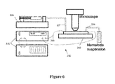
- FIG. 6 illustrates an electrotaxis device useful to study electrotactic response to AC electric field
- FIG. 7 graphically illustrates the AC electric field response of various C. elegans animals
- FIG. 8 shows the Pulse DC electric field signal wave-shape
- FIG. 9 graphically illustrates the effect of duty cycle on C. elegans pulse DC electrotaxis forward motion speed
- FIG. 10 shows the effect of duty cycle on C. elegans pulse DC electrotaxis turn response time (a) and percentage of responders (b);
- FIG. 11 graphically illustrates the effect of frequency on C. elegans and C. briggsae pulse DC electrotaxis forward motion speed
- FIG. 12 shows the percentage of responding C. elegans in less than (a) 40 s, (b) 20 s, (c) 10 s, and (d) 5 s, to pulse DC electric field at different frequencies and duty cycles;
- FIG. 13 shows the average response time of adult worms to pulse DC electric fields at different frequencies and duty cycles
- FIG. 14 shows an electrotaxis-based separation device for selecting C. elegans worms with identical electrotactic response
- FIG. 15 shows a field flow fractionation device for C. elegans
- FIG. 16 shows an electric trap device for electrotactic separation
- FIG. 17 shows an electric trap device (a) and electrotaxis response of C. elegans in the electric trap device (b);
- FIG. 18 shows a continuous flow worm sorter
- FIG. 19 shows the separation of adult worms from a mixture of adult and L3 stage worms in continuous worm sorter device at various flow rates and electric fields (a), as well as the population distribution among 4 output channels in the device with no electric field and a flow rate of 10 ⁇ L/min (b) and with an electric field of 4V/cm and 10 ⁇ L/min flow rate (c);
- FIG. 20 shows a semi-continuous electrotactic sorter
- FIG. 21 shows electrotactic behaviour and sorting of YA/L4 (a) and YA/L3 (b) mixed C. elegans samples in semi-continuous sorter device;
- FIG. 22 shows electrotactic sorting of YA and neuronal mutant (a) and YA and muscle mutant (b) mixed C. elegans samples in semi-continuous sorter device;
- FIG. 23 shows electrotactic sorting of young and old adult C. elegans mixed sample in semi-continuous sorter device
- FIG. 24 shows a storage ring channel for collection of separated worm with narrow distribution of electrotactic response
- FIG. 25 illustrates a microchannel array for parallel experimentation on multiple worms
- FIG. 26 shows an optical imaging chamber for worms
- FIG. 27 graphically illustrates movement behavior of worms treated with 6-OHDA using an electrotaxis assay
- FIG. 28 shows electrotactic analysis of movement behavior of worms exposed to Rotenone
- FIG. 29 shows electrotactic analysis of movement behavior of worms exposed to MPTP
- FIG. 30 shows plate level analysis of 6-OHDA exposed worms
- FIG. 31 shows plate level analysis of MPTP exposed worms
- FIG. 32 shows plate level analysis of Rotenone exposed worms
- FIG. 33 graphically illustrates YFP expression in a transgenic animal that expresses the DA transporter (a) and YFP expression following toxin-induced degeneration of DA neurons (b);
- FIG. 34 shows analysis of movement behavior of Acetaminophen pre-exposed worms against 6-OHDA, MPTP and Roteneone using electrotaxis assay.
- a method of inducing a response in a nematode in a microfluidic environment comprising exposing the nematode to an electric field that induces the selected nematode response.
- the response induced by an electric field such as a movement-induced response i.e. electrotaxis, has been determined to be reliable and highly reproducible.
- the electric field can be used as a powerful stimulus to efficiently control and orient nematodes as desired.
- exposure to the electric field is not harmful to nematodes since they continue to live normally and remain fertile following exposure to an electric field.
- nematode is used herein to refers to organisms of the animal phylum “Nematoda”, e.g. round worms, and particularly, to any round worm with amphid neurons that is expected to generate a response on exposure to an electric field.
- Examples of nematodes include, but are not limited to, Caenorhabditis elegans, C. briggsae and Oesophagotomum dentatum.
- An electrotaxis device may be used to practice the method of inducing a response in a nematode.
- the device uses an electrical signal to manipulate nematode movement.
- the device comprises a microchannel having first and second reservoirs formed at first and second ends of the microchannel.
- the first reservoir includes an inlet for input of a sample into the microchannel and the second reservoir includes an outlet for removal of fluid and/or sample.
- Each reservoir includes an electrode for use to establish an electric field between the reservoirs on connection to a power supply selected based on the electric field to be supplied (e.g. direct current vs. alternating current).
- any suitable electrode may be used such as metal electrodes, e.g.
- microchannel may be made of any suitable material that does not affect the application of an electric field, including polymeric materials such as organosilicon compounds.
- PDMS Polydimethylsiloxane
- the present electrotaxis method may be used to sort nematodes based on a differential response between different nematodes to a given electric field.
- the differential response between nematodes results from a distinguishing characteristic or parameter that exists between nematodes.
- the parameter may be, for example, developmental stage (age), size (length), a mutation affecting function of a neuronal or muscle gene and exposure to a chemical compound or drug that affects movement.
- the parameter may be, for example, developmental stage (age), size (length), a mutation affecting function of a neuronal or muscle gene and exposure to a chemical compound or drug that affects movement.
- nematodes of different ages may respond differently to a given electric field.
- adult nematodes exhibit a greater response on exposure to an electric field when compared to non-adult nematodes (e.g.
- L3-L4 stage nematodes L3-L4 stage nematodes
- shorter nematodes exhibit a greater response when compared with the response of longer nematodes.
- the term “response” is used herein to refer to one or more movement characteristics such as direction of travel, speed of travel, paralysis, body bends, turning time, extent of head movement and sinusoidal motion path, pauses and reversals.
- a method of separating nematodes based on a selected parameter comprising exposing nematodes to an electric field that induces a differential response among the nematodes based on the selected parameter, wherein the differential response functions to separate the nematodes.
- the differential response is induced by an electric field which is selected to promote a differential response based on a given parameter. If the nematodes are to be separated based on developmental stage, then an electric field of 2 V/cm or less may be selected, which is an electric field to which early stage nematodes do not respond and to which later stage nematodes do respond. If nematodes are to be separated based on length, an electric field of greater than 4 V/cm may be selected as nematodes shorter than wildtype exhibit a stronger response when exposed to this electric field than nematodes which are longer than wildtype.
- the electric field may be applied as a direct current (DC), alternating current (AC), a pulsed DC current and any other variations thereof useful for sorting purposes.
- DC direct current
- AC alternating current
- pulsed DC is effective to induce a turning response in nematodes.
- a method of sorting comprising the steps of accumulating nematodes at the proximal end of a separation channel on application of an accumulating electric field, inducing the nematodes to move along a separation channel by application of a separating electric field, and collection of separated nematodes in separate collection channels by application of a collecting electric field in a direction perpendicular to the separating electric field.
- the strength of each of the accumulating electric field, separating electric field and collecting electric field will be based on the strength of field suitable to achieve the desired action.
- the strength of the accumulating electric field may be in the range of about 2-16 V/cm
- the strength of the collecting electric field may be in the range of about 2-16 V/cm.
- the strength of the separating electric field will depend on the characteristics of the organisms to be separated, as discussed above, and in more detail herein.
- a microfluidic sorting device useful to conduct the sorting method comprises a nematode reservoir that feeds into a separation channel.
- a series of collection channels extend perpendicularly from the separation channel along the length of the separation channel.
- An accumulation electrode is positioned adjacent to the reservoir at the proximal end of the separation channel, a separation electrode is positioned at the distal end of the separation channel and a collection electrode is positioned within each collection channel.
- a cathodic potential is applied to the accumulation electrode to accumulate the nematodes. Following accumulation of the nematodes, a cathodic potential is then applied to the separation electrode to induce movement of the nematodes along the separation channel towards the separation electrode.
- a cathodic potential is applied to the collection electrodes to generate an electric field that is perpendicular to the separation channel (in the direction of the collection channels) to move separated nematodes into separate collection channels.
- a continuous field flow fractionation-type separation method is also provided.
- electric field is applied in a direction perpendicular to the direction of nematode movement in a pressure driven flow.
- the method comprises the steps of flowing nematodes through a separation channel in a first direction, applying an electric field to the separation channel in a direction perpendicular to the first direction to cause separation of the nematodes based on their response to the electric field and collecting the separated nematodes.
- the strength of the electric field is selected to achieve separation of a target nematode population from a mixture of nematodes.
- a continuous field flow fractionation device suitable to conduct continuous field flow fractionation comprising a separation channel having an inlet at its proximal end and a plurality of collection channels at its distal end. Separation electrodes are positioned along each side of the separation channel to provide an electric field on actuation of a power supply across the separation channel and perpendicular to nematode flow from the inlet to the collection channels.
- the separation channel may comprise a plurality of micropillars which function to maintain non-responsive nematodes (e.g. nematodes that do not exhibit electrotaxis) moving in a straight line towards the collection channels to facilitate separation.
- the micropillars may be equidistantly spaced in straight lines throughout the separation channel.
- nematodes are input into the device at the inlet by a pressurized flow towards the proximal collection channels.
- An electric field applied perpendicular to this flow between separation electrodes causes separation of the moving nematodes based on their response to the selected electric field, followed by collection of the separated nematodes in the collection channels.
- an electric trap device comprising a microchannel having a reservoir formed at first and second ends thereof which are connected by a channel comprising a narrowed electric trap portion.
- Each reservoir includes an electrode for connection to a DC power supply to generate an electric field across the microchannel from one reservoir to the other reservoir. The strength of the electric field is increased within the electric trap portion from the field applied to the microchannel.
- a first reservoir includes an inlet for input of nematodes, while the second reservoir includes an outlet for removal of fluids/sample. In use, nematodes are delivered into the first reservoir via the inlet and a constant electric field is applied between electrodes to induce electrotaxis of the nematodes towards the narrow electric trap.
- the narrowed electric trap functions to separate nematodes based on their ability to withstand the increased electric field, e.g. are not paralyzed by the increase in electric field strength. Nematodes that can withstand the increase in the electric field within the electric trap (and are not paralyzed by it), will pass through the trap to the second reservoir; however, if the electric field within the trap is such that it will paralyze the nematode (this is discernable by the nematode), the nematode will not pass through the trap.
- a method of separation which utilizes electric trapping.
- the method comprises the steps of inducing nematodes by application of a first electric field to move through a channel towards a narrow trap portion of the channel which exhibits a second electric field of greater strength than the first electric field such that it either permits or prevents passage of a target population of nematodes through the trap portion.
- the narrow trap portion of the channel exhibits a second electric field of increased strength such that certain populations of nematodes will not pass through the trap because the increased electric field within the trap is paralysis-causing.
- a continuous flow sorter device comprises multiple parallel microchannels with an array of spaced micropillars between each microchannel.
- Inlets are provided at the proximal end of each microchannel through which a flow of liquid/sample may be input via a pump into the device, and a series of collection chambers exist at the distal end of each microchannel to collect sorted worms. Electrodes are situated along the length of the device adjacent to the first and last microchannels of the multiple microchannels for the application of an electric field across the width of the device.
- a method of sorting using the continuous flow sorter comprises input of nematodes at the inlet of the first microchannel at a continuous flow rate, application of an electric field in a direction perpendicular to nematode flow sufficient to induce electrotaxis in select target nematodes.
- the select nematodes are then subjected to electric traps of increasing electric field strength such that separation of nematodes occurs when the field strength of an electric trap allows passage of some nematodes and prevents passage of other nematodes.
- a semi-continuous sorting device comprises a plurality of parallel electric traps which connect a loading chamber or reservoir to a separation chamber or reservoir. Electrodes situated at each of the loading and separation chambers provide a constant electric field from the loading to the separation chambers along the length of the electric traps on actuation (e.g. connection to a power source). Sorting of nematodes using this sorting device is similar to sorting achieved in a device with a single electric trap. Sorting is achieved by selection of an electric field that induces select nematodes to move from the loading chamber through the increased electric field within the electric traps to the separation chamber, while other nematodes are prevented from passing through the electric traps due to the increase field strength that occurs therein.
- a worm storage microchamber device is provided in another aspect of the invention.
- the storage device comprises a central chamber (e.g. 1-20 mm), which may be of any shape, for example, ring-shaped or an irregular ring-like shape, and includes a microfluidic inlet channel through which worms can be loaded into the device, and a microfluidic outlet channel for removal of the worms from the device.
- a narrow entropic trap (e.g. a width of about 10-200 um) comprising an electrode connects the inlet and outlet channels to the central chamber and prevents the movement of worms from the chamber into the channels. Worms inherently prefer to move without confinement.
- the entropic trap is of a size that restricts worm flexibility of movement. This reduction in entropy of movement leads to the worm to remain in the chamber. However, application of an electric field across the trap leads to a motive force that overrides the confinement effects, allowing the worm to progress through the trap at the inlet or outlet.
- a microfluidic channel array is also provided in a further aspect in order to analyse the movement of multiple single worms at one time. Worms can be arrayed into individual microchannels and their movement analysed on exposure to a drug or other chemical compound. Entropic traps at the mouth of each microchannel along with application of an electric field serve as a valve to allow movement of worms into individual microchannels. A electrical impedance sensor at the mouth of the microchannels near the trap will sense the arrival of the worm and cut off the trap electric field preventing any further worms from entering the microchannel. This feedback mechanism allow automatic arraying of several microchannels in parallel and ensure that each microchannel has a single worm.
- microchannels also integrate electrical or optical sensors that can initiate electrotaxis and measure the speed of the worm. Regions in which drugs of various types and concentrations can be dosed to determine their effect on the electrotactic speed of the worm are incorporated as described in detail herein.
- the present electrotaxis method may be used in movement-based high-throughput screening methods to identify candidate compounds that affect movement in selected nematode populations that may, for example, be representative of disease.
- a method of screening candidate compounds that affect nematode movement comprising measuring the initial or control movement characteristics of one or more nematodes, and then following exposure of the nematodes to a candidate compound, measuring the compound-induced movement characteristics of the nematode.
- a change in the movement characteristics of the nematode is indicative that the compound affects the nematode, e.g. to improve movement characteristics or to hamper movement characteristics.
- a combination of null mutations in dystrophin (dys-1) and MyoD (hlh-1) genes in C. elegans has been shown to cause progressive muscle degeneration similar to human DMD (Duchenne's Muscular Dystrophy) that impairs movement.
- the present electric field-based microfluidic channels may be used to screen for compounds that improve/restore movement in this mutants, thereby identifying potential candidates to test in human DMD patients.
- electric field-based assays may be used to study the mechanism of electrotaxis, as well as how the nervous system processes extracellular signals. Because movement is a complex behaviour that is controlled by many genes, the present methods will be useful to study the function of genes and pathways that mediate this behaviour.
- the present methods may be used to study neurodegeneration in C. elegans .
- the molecular mechanism of electrotaxis is yet to be elucidated, it is known to be mediated by neurons, most of which are located in the head region (e.g. amphid sensory neurons).
- an electrotaxis method of screening for compounds having neuroprotective properties in certain nematode populations mutants.
- the effect of a known neuroprotective compound, acetaminophen was determined to be neuroprotective to nematodes exposed to neuro-toxic compounds such as 6-OHDA, MPTP and Rotenone.-induced.
- FIG. 1 a An electrotaxis device suitable to study nematode response to an electric field is provided, as shown in FIG. 1 a .
- the device 100 comprises a microchannel 110 , as shown in FIG. 1 b , having a reservoir 106 formed at both ends thereof.
- the reservoirs 106 are connected via an assay channel 107 along the edge of which is an optional length scale 105 .
- One reservoir includes an inlet 102 for input of a sample into the microchannel, and the other reservoir includes an outlet 104 for the removal of fluid and/or sample.
- Each reservoir 106 also includes an electrode 108 to establish an electric field from one reservoir to the other reservoir by connection to a power supply 112 .
- Flow of sample into the microchannel 110 via inlet 102 may be achieved by a suction pump 114 connected to outlet 104 .
- the device may comprise: (i) a worm handling unit (syringe pump, sample container, inlet, and outlet pipes), (ii) a monitoring unit (digital camera and microscope lenses), (iii) an actuation unit (power source and electrodes), and (iv) a microchannel device (sealed PDMS microchannel with embedded electrodes in reservoir areas).
- the microdevice consists of a simple microchannel instrumented with electrodes (5 cm apart) within the reservoirs.
- the microchannel 110 of the device 100 may be any appropriate size, including, e.g. 300 ⁇ m-wide, 80 ⁇ m-deep, and 5 cm-long.
- the microchannel 110 was fabricated using soft lithography as described (Xia et al. Annu. Rev. Mater. Sci., 1998. 28: p. 153-184).
- the mask layout was designed in AutoCAD (Autodesk Inc., San Francisco, USA) and printed using ultra high-resolution laser photo plotting on transparency sheet.
- SU8-100 (80 ⁇ m-thick) negative photoresist (MicroChem. Corp., MA, USA) was used to lithographically pattern a master mold of the device.
- Polydimethylsiloxane (PDMS) pre-polymer mixture (Sylgard 184 kit, Dow Corning Corp., MI, USA; 10:1 ratio of the base and cross-linker) was then cast on the master mold, and cured at room temperature for 24 hours.
- the PDMS replica was then peeled off the master mold and cut into pieces containing individual channels. The inlet and outlet access ports were punched out at the reservoir areas.
- the top surface of the PDMS replica and a bare PDMS piece of the same size were plasma oxidized (50 W for 30 s), micro-contact printed with PDMS pre-polymer, and bonded, sealing the microchannel.
- Inlet and outlet capillary glass tube tips (VWR International, USA, catalog number CA14672-380, 1.5 mm outer diameter, 20 mm long) were connected to the punched areas.
- Plastic tubes Saint-Gobain Performance Plastics, OH, USA, TYGON R-3603, 2.4 mm outer diameter and 10 cm long were connected to the inlet and outlet glass tubes.
- Metal electrodes (Arcor Electronics, USA, C24, copper 0.5 mm diameter) were inserted into the reservoir areas by punching through the PDMS elastomer from the side. Liquid PDMS pre-polymer was then used to seal the surrounding areas of the electrodes and the device was placed on a hot plate (120° C.) to cure. The device was then attached to a glass cover slip again using PDMS pre-polymer and cured.
- a syringe pump KD Scientific 14-831
- the inlet and outlet pipes were then leveled to the same height preventing the possibility of pressure-induced flow.
- the electric field (generated using KEITHLEY 2410 as a power source) was then applied and the response of the worm was recorded. Electrical resistance of the channel filled with the buffer M9 solution in all tests was ⁇ 0.68 M ⁇ . The videos were recorded to obtain raw data.
- Worms were grown at room temperature (20° C.) on standard NG agar plates seeded with OP50 E. coli bacteria as previously described by Brenner (Genetics, 1974. 77(1): p. 71-94).
- the strains used in this study are: wildtype N2, BC347 unc-54(s74), CB78 unc-6(e78), PS55 lon-2(e678), and PS250 dpy-5(e61).
- the PS55 strain also carries a him-5(e1490) mutation that increases frequency of males in the progeny.
- the N2 strain was used as a wild-type reference in all assays. All strains are available at Caenorhabditis Genetics Center (Minnesota, USA).
- a length measurement scale was microfabricated alongside the microchannel as shown in FIG. 1 b .
- the response of worms to different ranges of electric fields was recorded by a camera (Nikon Coolpix P5100, NY, USA) and analyzed by Image) software (http://rsbweb.nih.gov/ij/) and AutoCAD (http://www.autodesk.com).
- ImageJ software was used to analyze videos and obtain the snapshots (every 0.07 s) of recorded movies of worm movements.
- the sequenced images were used to measure the distance traveled by the worm inside the channel.
- the initial and final snapshots were imported into the AutoCAD software and the traveled length was measured by superimposing lines on the worms' pathway and comparing the line lengths to a reference length bar in the image. Snapshots obtained from ImageJ software was used to measure the worm movement distance between length scales fabricated on the device. The worms' lengths were also measured by linear approximation method using AutoCAD software. One image of each tested worm was imported to the software. A total of 15 lines were drawn on the worms' body image. The lengths of the lines were added and the total length was compared to the reference value to determine each worm's length. This process was repeated three times for each worm and an accuracy of about 10 ⁇ m was obtained.
- An electrotaxis device incorporating a microchannel format allows electric streamlines to be confined and directed along the axis of the channel and provides a simple well-controlled format to study and understand the electrotaxis of C. elegans .
- Straight microchannels e.g. 5 cm long and 80 ⁇ M deep
- widths 2 mm, 1 mm, 500 ⁇ m, 300 ⁇ m, and 150 ⁇ m were utilized.
- worms In the presence of low-voltage electric fields, worms exhibited electrotaxis and moved in a directed manner towards the negative pole.
- electrokinetic flows electrokinetic flows
- dead worms were loaded individually into the channels filled with M9 solution and positioned in the middle section (2.5 cm away from the electrodes) using a syringe pump.
- a wide range of electric field strengths (1-20 V/cm) was applied across the channel that showed that electrokinetic flow above 13 V/cm was able to move dead worms towards the anode. No change in the morphology of dead worms was observed during this process.
- electrokinetic effects electrokinetic effects (electrophoresis of the worm and electro-osmosis of fluid) had no significant role in the movement of worms below 13 V/cm in these confined geometries.
- L3 stage worms (385-528 ⁇ m-long, dark rectangles) responded to electric fields above 4 V/cm with a speed range of 100-216 ⁇ m/s.
- L4 stage worms (534-725 ⁇ m-long, clear rhombuses) responded to the electric fields between 4 and 10 V/cm with a speed range of 220-340 ⁇ m/s. Due to the partial paralysis at 12 V/cm, the speed of L4 stage worms was reduced.
- the young adults (920-1,050 ⁇ m-long, dark circles) had the lowest effective electric field range (2-4 V/cm) since they were paralyzed above 4 V/cm. Within the effective range, their speed ranged between 296 and 471 ⁇ m/s. The upper threshold electric field was not observed for L3 stage worms due to the upper limit of allowable field without electrokinetic flow.
- L3 stage animals responded to the electric field robustly starting from 4 V/cm (minimum threshold).
- the maximum threshold (defined by the paralysis phenotype) could not be observed because animals continued to swim normally without a change in speed even at the maximum allowable field (12 V/cm with no electrokinetic flow effect) in the channel.
- animals appeared more sensitive to the electric field.
- L4 stage animals were partially paralyzed at 10 V/cm (revealed by occasional abnormal body bends and reduced speed), the young adults exhibited this effect at 4 V/cm.
- the minimum threshold response at these two stages was 4 V/cm (L4) and 2 V/cm (young adult). Reversing the applied electric field resulted in the reversal of the worm's movement.
- Mutant worms with defects in specific cell types were used to explore the cellular basis of electrotaxis using methods as described by Gabel et al. (J Neurosci, 2007. 27(28): p. 7586-96) and unc-6(e78) mutant animals that exhibit defects in neuronal differentiation.
- Studies on unc-6 have shown that it encodes a netrin-like secreted protein that plays a crucial role in neuronal growth cone migrations.
- the unc-6 mutant animals are uncoordinated due to defects in dorsal and ventral nerve cords.
- the average speed of various animals in a 5 cm-long, 300 ⁇ m-wide and 80 ⁇ m-deep microchannel was determined.
- the analysis of unc-6(e78) young adults in the microchannel revealed no response to the electrical stimulus and showed no obvious sign of orientation and speed change following the application of electric fields ( FIG. 4 ).
- a muscle mutant unc-54(s74) was also tested in a similar setting to determine the contribution of muscles in electric field-driven swimming behaviour.
- the unc-54 gene is necessary for the proper differentiation of the muscle myosin class II heavy chain (MHC B).
- the unc-54 mutant animals exhibit disorganized muscles and are severely uncoordinated (paralyzed).
- the unc-54(s74) young adult worms responded to the electric field in a manner similar to that of wild-type worms (2-4 V/cm range) although their speed was significantly slower (unc-54: 88 ⁇ m/s, wild type: 380 ⁇ m/s, average speeds) ( FIG. 4 ).
- dpy-5 (e61)
- lon-2 (e678)
- the dpy-5 gene encodes a collagen that is necessary for the cuticle formation in developing larvae
- lon-2 encodes a glypican family of heparan sulfate proteoglycans that negatively regulates DBL-1/BMP signaling to control body length. Mutations in these two genes give rise to opposite phenotypes.
- the Ion-2 mutant animals are roughly 30% longer (1,300 ⁇ m+/ ⁇ 100 ⁇ m at 62 hours) than wild type. Both these mutant animals are otherwise healthy and active.
- dpy-5(e61) animals in the microchannel revealed that, unlike wild type animals (effective response range of 2-4 V/cm), these animals responded to the electric field robustly starting from 4 V/cm and showed no sign of paralysis at the highest possible field tested (12 V/cm). Their average speed (106 ⁇ m/s) did not change in response to an alteration in the electric field strength and/or direction. In contrast, the lon-2(e678) animals did respond to the lowest threshold electric field like wild type (2 V/cm). However, these animals appeared extremely sensitive and were paralyzed under the influence of electric fields higher than 3 V/cm. Due to their larger size, they were unable to move freely in the microchannel and exhibited abnormal movements. This precluded measure of their speed.
- C. elegans behaviour in a microfluidic environment was studied in the presence of a low voltage electric field and was determined to be useful as an attractant to guide their movement without physiological and behavioural side effects.
- Application of electric field in worms induces forward movement towards the cathode that is robust, highly reproducible, and sensitive.
- the electric field response was measured in microchannels at a range of electric field strengths (with minimum and maximum thresholds) within which an optimum electrotactic response was observed. Not all stages of animals responded equally well within the same threshold range. Thus, while the effective range for L4 larvae was 4-10 V/cm, adults appeared significantly more sensitive and had a lower response threshold (2-4 V/cm). Within the optimum range at any given stage, the speed of movement of animals remained unchanged suggesting that the electric field response is a binary phenomenon (all or none). All responding stages of animals (L3, L4, and young adult), when exposed to the electric field above the maximum threshold, exhibited paralysis as judged by their near rod-like shape and abnormal body bends. This effect was reversible since the animals resumed normal movement upon lowering the electric field. Furthermore, it was demonstrated that the electric field manipulation of C. elegans does not appear to be harmful since the exposed animals, when placed on standard culture plates, resumed normal movement and feeding behaviour and continued to reproduce normally.
- C. briggsae is very similar to C. elegans in terms of morphology, development, and genetic makeup.
- C. briggsae responded to electric fields in a range of 1-4 V/cm and showed partial paralysis starting at 5 V/cm. Consistent with this, the electrotactic movement speed at 5 and 6 V/cm was significantly lower compared to 1-4 V/cm (p ⁇ 0.01, ANOVA).
- the paralysis was initially observed in the tail region as animals appeared to gradually form coiled-shape configuration in the tail region which extended to the whole body if the signal persisted, eventually leading to coiling.
- the higher threshold of response (4 V/cm) of young adult C. briggsae was similar to that of C. elegans , it was observed that these animals, unlike C.
- the device 200 consists of a microchannel component 202 (e.g. 5 cm-long, 300 ⁇ m-wide, and 80 ⁇ m-deep) comprising a reservoir 204 a , 204 b formed at each end connected by a channel 205 marked with a length scale.
- a microchannel component 202 e.g. 5 cm-long, 300 ⁇ m-wide, and 80 ⁇ m-deep
- An inlet 206 feeds into one reservoir 204 a from a sample holder (e.g. worm sample), while an outlet 207 extends from the second reservoir 204 b and is connected to a syringe pump 208 .
- Electrodes 209 and 210 (cathode 209 and anode 210 ) were embedded at both reservoirs and connected to a power supply unit 212 (an electric signal generation, e.g. amplifier and function generator) that applies different waveform AC electric fields.
- the microchannel 202 was constructed of polydimethylsiloxane (PDMS) pre-polymer using soft lithographic and contact printing methods as described above.
- PDMS polydimethylsiloxane
- Worms were loaded individually into the microchannel 202 using a syringe pump 208 and placed in the middle (2.5 cm away from each electrode). A constant DC electric field was applied across the channel to stimulate animals to initiate swimming towards the cathode for a short distance (3 mm). Afterwards, an AC electric field with square waveform (frequency between 20 mHz and 3 KHz) was applied and the response of animals was recorded using a camera. Results are shown in FIG. 7 . Normalized traveled range (Traveled Range/Average stage length) decreases with frequency increase for all stages.
- Regions I, II, III correspond to DC-like electrotaxis, 1-directional movement, and localization frequency range respectively, illustrated for wild type (dashed double side arrowed lines) and muscle mutant nematodes (solid double side arrowed lines).
- Applied electric field was 10, 8, 6, and 3 V/cm for L2, L3, L4, and young adult (YA) stages respectively.
- Average length for each developmental stage is as follows: L2 (320 um), L3 (470 um), L4 (680 um) and YA (900 um).
- Synchronized worms of various ages were tested using the same square waveform and frequency range. The results are shown in FIG. 7 . All developmental stages (except for L1 stage) responded to the AC electric field in the same manner as young adults but with a slight variation in their range of localization. All stages demonstrated decreased traveled range with increase in frequency. Frequencies above ⁇ 1 Hz appeared to localize worms but as shown in FIG. 7 , older animals responded more robustly to the AC electric field (average normalized traveled range of 0.41 for young adults and 0.91 for L2 stage for f ⁇ 1 Hz). For the older animals, more instantaneous responses to the AC electric field compared to the younger ones was observed.
- the outlet tube 207 was connected to a syringe pump 208 .
- Soft lithography technique was utilized for the fabrication of the microchannel 202 in polydimethylsiloxane (PDMS) material.
- the electrodes 205 were connected to an electric signal generation unit 210 (comprising a function generator and amplifier) for the application of electric fields and hence currents in the channel.
- This unit consisted of a AFG3022B function generator (Tektronix Inc., OR, USA) with a maximum voltage output of 5 V, a 677B amplifier (TREK Inc., NY, USA) with a 400 gain, a custom made simple switch to reverse the polarity of electrodes, and copper wires to connect the setup to the device electrodes.
- the waveform of the pulse DC signal is shown in FIG. 8 .
- the signal rises in a step-like manner from zero to a maximum set point for a controllable duration of time (duty cycle) and decays to zero for the rest of the signal cycle which is then repeated at a fixed frequency.
- Duty Cycle (%) f ⁇ t on ⁇ 100 (1) where t on is the on-portion time of the pulse signal. Since the maximum pulse electric field strength (EF max ) output of the function generator did not exceed 1 V/cm, the signal was subsequently amplified and applied to the microdevice.
- the rise and decay time of the pulse signal were 50 ⁇ s each, which restricted the experimental frequency range to less than 1 kHz and the duty cycle to more than 10% in order to produce a rectangular-shape pulse waveform.
- the C. elegans N2 and C. briggsae AF16 strains were grown on standard NG agar plates previously seeded with OP50 strain of Eschericia coli and maintained at 20° C. Synchronized worms were used in all the experiments. For this, gravid adult hermaphrodites were treated with bleach solution (commercial bleach and NaOH (4N) in the ratio of 3:2). After bleach treatment, dead worms were washed with M9 solution (3 g KH2PO4, 6 g Na2HPO4, 5 g NaCl, 1 ml MgSO4 (1M) in 1 liter). Embryos were hatched in M9 following 24 hours incubation such that hatched worms were arrested at L1 stage. The animals were plated on NG agar plates and grown till they reached adulthood.
- bleach solution commercial bleach and NaOH (4N) in the ratio of 3:2
- M9 solution 3 g KH2PO4, 6 g Na2HPO4, 5
- synchronized worms were individually loaded into the microchannel from a reservoir of diluted worm suspension (in M9) and positioned at the center of the channel by applying suction at the outlet.
- the inlet and outlet tubes were then leveled to the same height to prevent any flow in the channel.
- the head orientation of the worm was then determined in the microscope.
- the worms moved randomly in either direction (left or right) or remained stationary within the channel.
- the electric field either constant or pulse DC
- the electric field was then applied along the channel (parallel to worm's body) in a direction opposite to its head orientation.
- the resulting movement response was digitally recorded using a camera (Coolpix P6000, Nikon Inc., Tokyo, Japan) connected to the microscope for the entire duration of the experiment.
- the applied stimulus either forced the worm to turn inside the microchannel and move towards the cathode at its rear or did not generate any response.
- forward motion speed under signal application and turning time under signal reversal were measured from the video as behavioural phenotypes. Since there was a large variation in turning response time between individual worms in the case of pulse DC signal, and to identify the responding worms after each field reversal, the worm was allowed to sense the signal reversal and initiate a turn response for up to 40 s immediately after the signal reversal.
- the worm was considered either a responder, if it turned within the given time window, or non-responder, if this time elapsed without a turn.
- the aggregate population response time was then used for data analysis.
- the turning time data was recorded for different durational intervals (i.e. 5, 10, 20, and 40 s).
- the responder worms were allowed to swim towards the cathode for a distance of 5 mm after which the polarity of the electrodes across the channel was reversed and the worm's behaviour was recorded. This process was repeated thrice for each animal to rule out a random electrotactic turning response.
- the duration of the electric field stimulation of the worm can be adjusted by changing the duty cycle of the signal as shown in FIG. 9 .
- this method has the potential to provide information about the response time of a population of worms to electrical signals. For instance, if the pulse width of the signal is below the response time of the animal, then that signal will not elicit a movement response even when an indefinite number of cycles of this signal is applied.
- the speed of the worms remained constant with average values between a minimum of 290 ⁇ 37 ⁇ m/s and a maximum of 360 ⁇ 24 ⁇ m/s at different duty cycles (30%-90%, robust response range shown in FIG. 10 b ) as shown in FIG. 10 a .
- the average turning time for a 3V/cm DC electric field was measured to be 6.6 ⁇ 2.6 for 100% of responder YA worms.
- the time for the worms to turn around in response to pulse DC signals varied significantly ( FIG. 10 a ) for certain duty cycles even though the experiments were done on a homogenous population of young adults.
- This variation in response time was greatest when the duty cycle was the smallest (large standard deviations at low duty cycles in FIG. 10 a ) and was reduced as the duty cycle increased and the signal approached constant DC.
- a lesser number of worms responded in the 40 s window at very low duty cycles. For instance, no worm responded at 10% duty cycle in less than 40 s and the turn response was first observed at 20% duty cycles.
- FIG. 10 b plots the percentage of worms that responded to the pulse DC signal (at 1000 Hz frequency) of a certain duty cycle in a specific time window (i.e. 5, 10, 20 and 40 s).
- a specific time window i.e. 5, 10, 20 and 40 s.
- comparatively fewer worms responded quickly to the reversal of the pulse DC signal.
- 20% of the worms responded to 20% duty cycle signal with a turning response time of 5 s or less.
- 60% of them were able to respond to the change in direction within 40 s.
- the duty cycle of the signal was increased, an increasing proportion of the worms responded to the signal in a faster manner.
- the proportion of the worms responding to the reversal of signal within 5 s increases from 20% at 20% duty cycle to ⁇ 80% at 90% duty cycle.
- the majority of worms responded later to the field reversal and their turning time was prolonged. This phenomenon could be related to the time required for the polarization of the neurons that mediate the movement response.
- This variation in duty cycle of pulse signals and turning response time to field reversal together provide a unique method to elicit varying movement response to correspondingly varying electrical stimulus.
- This technique can be used to precisely study the turning behaviour of nematodes and the neurons and genes involved in this behaviour.
- HTS high-throughput screening
- the present integrated microelectrodes do not interfere with the normal behaviour of the worm.
- One approach is to microfabricate hydrogel coated metallic electrodes so that the worms are exposed to only ionic currents.
- Various methods to integrate the hydrogel with electrodes such as photolithographic based microfabrication, and to construct gel-filled microchannels as electrodes are possible.
- Liquid electrodes consist of microchannels filled with highly conductive liquids and gels such as polyelectrolytes, polyelectrolyte gels and agarose gel, and interfacing with the main microfluidic channels through a high density nanoporous membrane, e.g.
- a polycarbonate porous membrane that effectively transmits ionic current and potential into the channel but prevent transport of biological material across it.
- the effect of pore size and pore density (e.g. a pore size of 1 to 5 micrometers and density of 2 ⁇ 10 7 to 4 ⁇ 10 5 pores/cm 2 , respectively) on the electric field distribution may be optimized to design a suitable electrode that imposes electric field but does not affect the functioning of the worms or the assay in any way.
- the sensing will be done by measuring the impedance of the microchannel cross section using electrodes that are embedded in the bottom surface of the microchannel.
- the impedance measurement depends on the permittivity of the fluid filling the microchannel.
- a microfluidic sorter 300 is provided.
- the sorter 300 comprises a worm reservoir 310 , a separation channel 312 and a series of collection channels 314 which extend perpendicularly from the separation channel at various lengths across the separation channel 312 .
- An accumulation electrode 316 is positioned adjacent to the reservoir 310 at the proximal end of the separation channel 312
- a separation electrode 318 is positioned at the distal end of the separation channel 312 .
- the sorter 300 separates worms into sub-groups based on electrotactic response to a constant electric field.
- the worms were loaded into the reservoir 310 .
- An electric field (cathodic potential) was applied to the accumulation electrode 316 to collect the worms. Once a sufficient number of worms accumulated, the polarity was switched and the separation electrode attained cathodic polarity.
- the worms then moved along the separation channel at various speeds based on their electrotactic response. Once sufficient separation was been achieved, electric field was applied in the perpendicular direction via collection electrodes within the collection chambers to move the iso-electrotactic sub-groups into individual collection channels 314 . Separation of worms based on their size and electrotactic response in a microchannel was achieved using this sorter
- continuous field flow fractionation-type separation sorter 400 is provided.
- electric field is applied in a direction perpendicular to the direction of worm movement in a pressure driven flow.
- the sorter 400 comprises separation channel 412 having an inlet 410 at its proximal end and collection channels 414 at its distal end.
- Separation electrodes 416 and 418 are positioned at either side of separation channel 412 and function to provide an electric field across the channel 412 , perpendicular to worm flow.
- the channel 412 comprises a plurality of micropillars 315 which function to provide confinement in the vertical direction, enabling worms that are non-responsive to the electric field to move along a straight line in the horizontal direction.
- Worms were introduced at a constant small flow rate of 10-40 ⁇ l/min at the inlet 410 .
- a constant electric field of 4-5 V/cm was applied in the vertical direction between the two separation electrodes 416 and 418 .
- Responsive worms thus, moved horizontally with the flow and vertically based on their electrotactic response.
- the worms of similar electrotactic response were separated vertically and collected in different collection channels 414 . This format allowed for continuous separation of the worms based on their electrotactic response.
- electrotaxis was used to control the movement of C. elegan in a 4-way micro-junction.
- the device comprised 4 microchannels, a,b,c and d meeting at a junction. Each microchannel had a reservoir at the other end with an electrode inserted in it.
- the worms in a diluted suspension were fed into the bottom reservoir (c) of the device with a 10 ⁇ l/min flow rate moving towards the junction.
- Electric fields were applied desirably from a to b channels (linearly, from side a reservoir to side b reservoir), from a to d (from side to top reservoir) and a to d (from side to top reservoir).
- the worm arriving at the junction with the flow travels the cathodic channel, despite the fact that, at the junction, it could choose to move into the other two channels with no electric field or anodic bias.
- the device 500 includes a single main PDMS microchannel 510 (e.g. 120 ⁇ m deep, 300 ⁇ m wide and 30 mm long in total) having a reservoir at both ends 511 , 512 which gradually narrow to an electric trap center 514 .
- the electric trap center 514 may be 100 ⁇ m wide and 3 mm in length.
- the reservoirs 511 , 512 each include an electrode 516 and 518 for connection to a DC power supply and generation of an electric field across the channel 510 .
- One of the reservoirs 511 includes an inlet 515
- the other reservoir 512 includes an outlet 517 .
- a range of electric fields (black column in FIG. 17 b ) were found to induce electrotaxis and made the worms move towards trap 514 . As illustrated, this range is different for different stages of the worm, e.g. YA (2-5 V/cm), L4 (4-11 V/cm), L3 (5-15 V/cm) and L2 (7-21V/cm).
- the electric field within the electric trap 514 is however always 3 fold higher than the reservoir 511 . Trap electric fields which cause partial paralysis of the worm when it enters into this section also vary with the stage of the worm (gray column in FIG. 17 b ). However, it was observed that above the higher threshold of the gray column, worms avoid entering the trap section since they would become completely paralyzed.
- the YA worms did not enter the electric trap 514 but instead remained in reservoir 511 , while L3 worms continued to move through trap 514 into reservoir 512 .
- This behaviour led to automatic self sorting of the L3 worms (passed through the trap into the second reservoir) from the YA worms (did not pass through trap, but remained in first reservoir).
- a continuous flow sorter device 600 as shown FIG. 18 is also provided.
- the device 600 comprises multiple parallel main microchannels 610 (e.g. 500 ⁇ m-wide and 80 ⁇ m high each) with an array of micropillars 612 formed between each microchannel 610 .
- Inlets 614 are provided at the proximal end of each through which a flow of liquid/sample may be input via a pump into the device, and a series of collection chambers 615 exist at the distal end of each microchannel to collect sorted worms. Electrodes 616 and 618 are situated along the length of the device adjacent to the first and last microchannels of the multiple microchannels for the application of an electric field across the width of the device 600 .
- Electric field was applied perpendicular to the microchannels 610 . Worms were introduced into the device at inlet 614 a (inlet of the first microchannel of the multiple) with a continuous flow in all four microchannels using syringe pumps. When a potential is applied perpendicular to the flow (between electrodes 616 and 618 ), the electric field between the micropillars 612 is greater than that in the microchannel regions. Since the spacing between micropillars 612 decreases from the first microchannel 612 ( 1 ) to the last microchannel 612 ( 4 ), the electric field between micropillars also increases as shown in FIG.
- E1 was set in a range of response for the desirable worms while providing micropillar electric fields so as to exclude other stages of worm.
- an efficiency parameter was defined as:
- ⁇ i ⁇ [ % ] ⁇ G i G 0 - H i H 0 ⁇ ⁇ 100 ( 2 )
- G 0 and H 0 represent the total number of adult and L3 worms fed into the device.
- FIG. 19 b Distribution of worms among the 4 outlet channels with no electric field and 10 ⁇ l/min flow rate is shown in FIG. 19 b .
- Increasing the electric field enhanced the efficiency up to 72.9% for adult worms with an optimum flow rate and electric field of 10 ⁇ L/min and 4 V/cm ( FIG. 19 c ).
- the optimum represents the balance between the electrotactic response of the adult worm and its residence time in the microchannel dictated by flow velocity.
- High electric field intensity in the second micropillar row (E3) prevented adult worms from passing from channel 2 to 3 in FIG. 19 c .
- E3 By lowering the E1 value and hence E2-4, worms can be collected from output 3 and 4 as well.
- a semi-continuous sorting device 700 (120 ⁇ m-deep) is shown in FIG. 20 .
- the device 700 consists of a plurality (e.g. 20) of parallel electric traps 710 as described above (e.g. 100 ⁇ m-wide, 500 ⁇ m-long, 400 ⁇ m pitch) which connect a loading chamber 712 to a separation chamber 714 (e.g. each 8 mm by 1.5 mm). Electrodes 716 , 718 were situated at each of the loading and separation chambers 712 , 714 in order to maintain a constant electric field throughout the device 700 across the electric traps 710 .
- 100 ⁇ m-diameter Pt wire was inserted inside the loading and separation chambers perpendicular to the axes of the electric traps 710 to produce the electric field.
- An inlet 720 is provided to input worms into the loading chamber 712 and an outlet 722 is provided to collect separated worms from the separation chamber 714 .
- Worms of two different developmental stages which were easily distinguishable by size were separated using this device 700 .
- a range of electric fields e.g. 3.5-7.1V/cm
- the number of attempts that the worms made towards entering the electric traps as well as the number of successful passages through it towards the separation chamber 714 were counted for each developmental stage of C. elegans .
- the percentage of worms (out of attempted ones) passing through the trap is shown for YA/L4 and YA/L3 in FIG. 21 a/b , respectively.
- Sorting experiments were repeated 3 times. As shown in FIG. 21 , greater than 65% of the YA worms passed the electric field traps until the field in the electric trap was 14 V/cm. However, upon increasing the electric trap field strength, the percentage traversing through the trap dropped quite significantly to under 5% at 28.4 V/cm. On the other hand, this increase in electric field across the trap did not significantly affect the percentage of L3 and L4 worms passing through the electric trap and the number passing through the trap remained consistently above 60%. Between the L3 and L4 stages, the L3 worms had a higher percentage passing through the trap ( ⁇ 80%) at 28.4 trap electric field as compared to L4 ( ⁇ 60%).
- the critical electric field needed to inhibit the worm movement for a particular stage was on an average higher than that obtained in single trap experiments ( FIG. 17 b ) for all tested stages. This is believed to be due in most part to the shorter length (500 ⁇ m, 80% shorter) of the electric traps in the sorter device 700 , resulting in less exposure time of the worm to the high strength field while attempting to pass.
- Muscle (unc-54(s74)) or neuron (unc-6(e78)) mutant animals were mixed with YA stages in a 1:1 ratio.
- the wild type YA worms had GFP markers in them to distinguish them easily from the mutants.
- the sorting process was conducted for >50 worms at an electric field of response for adult animals (3.4 V/cm).
- the magnitude of the electric field in the trap was set so that the wild type YAs which respond to the electric field would be able to pass through the trap.
- the mutants would generally not pass through the trap due to the electric field.
- the worms that were able to cross the electric trap were collected from the separation chamber in a Petri dish and counted under the florescent microscope.
- a microfluidic storage device 800 as shown in FIG. 24 , is provided that stores worms and permits their continuous circulation.
- the device 800 comprises a ring-shaped microchannel reservoir 810 having an inlet 812 and an outlet 814 which include entropic traps 815 such that in the absence of an electric field the entropic variation between the reservoir 810 and the inlet 812 /outlet 814 prevents escape of the worms.
- entropic traps 815 such that in the absence of an electric field the entropic variation between the reservoir 810 and the inlet 812 /outlet 814 prevents escape of the worms.
- Iso-electrotactic worms arrive at the inlet channel 812 and are prevented from entering into the device due to the entropic trap 815 .
- Actuation of an injection electrode 816 at the inlet 812 and the let side control electrode 818 (cathode) creates an electric field that allows the worms to be injected into the storage ring 800 .
- the dimensions of the ring are such that the worm under random motion will prefer to reside in the larger microchannel 810 rather than enter the narrow confinement of the entropic trap 815 at the inlet 812 or outlet 814 .
- Sufficient food (M9 solution) and oxygen can be provided by recirculating the fluid in the storage ring using macroporous membranes (1-10 micrometers pore size) that retain the worm within the device.
- macroporous membranes (1-10 micrometers pore size) that retain the worm within the device.
- entropic traps may be used to optimize a protocol for efficiently capturing worms based on their age/size.
- the entropic traps may be integrated with the microchannel storage ring and optimized for worms of various age/size.
- Nutrient delivery means may also be included within the entropic traps to grow worms in a physiological manner.
- macroporous membranes pore sizes 1-10 ⁇ m
- a microchannel array device 900 as shown in FIG. 25 , is provided.
- the device 900 comprises a worm storage reservoir 902 which is connected to a single worm holding unit 904 at the base of each of a plurality of parallel assay microchannels 910 .
- Each assay channel 910 is to be populated by a single worm.
- the application of an electric field at an impedance-based entrance worm detector 906 simultaneously drives the motion of worms from the storage reservoir 902 to each assay channel 910 in parallel.
- the entrance of the worm into an individual assay channel 910 is detected electrically by the impedance based worm detector 906 , and this feedback shuts off electric stimuli selectively in that channel, ensuring that only one worm is loaded into each channel.
- Storage rings as described in Example 10, may be connected to individual assay channels via microfluidic connectors on the storage rings which have the same electrical resistance as the assay channel so that the electric field applied across the individual channels and hence the electric stimuli to the worms are identical. This will ensure that the worms populate the individual assay channels, simultaneously.
- Entropic traps 905 may be integrated at the entrance of the assay channel so that once one worm has entered and the electric field shut off, the trapped worm will not be allowed to exit. Since the arraying technique is electrical-based, an external circuit will multiplex and probe several thousands of these sensors in real-time to identify the event of a single worm entering an individual assay channel for thousands of channels in parallel.
- Arrays of 100 microchannels, 1 cm in length, are typical.
- the array may have a common inlet for connection to the storage ring when desired to access worms of similar electrotactic response.
- the assay entrance valve 905 permits loading and confinement of loaded worms inside the assay channel 910 .
- the entrance worm detector 906 provides electrical feedback to ensure that only one worm is loaded in each assay channel, e.g. via impedance or capacitance-based position detectors. As soon as one worm enters the region of detection, a feedback signal renders the detector to be anodically biased to prevent others worms from entering the channel, and the trapped worm from exiting.
- the fluid inlet 912 and outlet 914 channels are used to recirculate fluid (M9 solution) to maintain the physiological condition of the worm.
- the drug injection channel 915 comprises a nanoporous interface 916 for injection of defined quantities of drug compounds dynamically or in a pulsed fashion into the assay channel 910 .
- the electrical drug injection method allows automated dosing of various combination and doses of drugs into a large number of microchannels simultaneously. Once the worms have been incubated with the drug, they are electrically collected at the entrance of each assay channel 910 and simultaneously made to traverse the channel 910 to determine movement characteristics.
- the worm detector 908 (similar to detector 906 ) at the end of the channel 910 detects the arrival of the worm. Worms that have been exposed to drugs that remedy their neurodegenerative behaviour will arrive at the end and these chemicals and their doses can be identified.
- the worms exposed to chemicals for 3 days inside microchannels may be examined by electrotaxis.
- the speed of worms or the time of their arrival at a detector at the far end of the channel may differ from a control worm, e.g. a Htn-polyQ control worms.
- the drug dosing region 916 comprises a nanoporous region that interfaces the assay channel to a microfluidic network above it, capable of convectively transporting various drugs or drug combinations to this location.
- Electrophoretic pumping can be used to transport precise and defined quantities of drugs into the assay channel in order to expose the worms to the drug.
- Electrophoretic pumps formed in the nanopores of the membrane can effectively be used to achieve digital dosing control of macromolecules, proteins and DNA in a reliable and repeatable manner. This proven method can be used to dynamically control the dosage of drugs into the microchambers over a period of time.
- the worms may be confined underneath the nanoporous membrane to ensure sufficient exposure. This confinement is achieved simultaneously across all assay channels.
- application of an AC electric field at certain frequency ranges may be used to immobilize the worms in certain locations.
- the worms may be isolated, few in number, that have been favourably or adversely affected by the screening and obtain high content information from them.
- Microfluidic chambers, as shown in FIG. 26 that provide optical fluorescence images at multiple angles are provided to study these selected organisms in detail.
- 6-OHDA catalog no. 162957
- Rotenone catalog no. R8875
- Acetaminophen catalog no. A7085
- MPTP M325913
- Desired concentrations of 6-OHDA 100 ⁇ M
- MPTP 700 ⁇ M
- Rotenone 25 ⁇ M
- 6-OHDA solution is sensitive to light and therefore it was kept in the dark.
- a stock solution of Acetaminophen (10 mM) was prepared and stored at ⁇ 20° C. At the time of toxin assay, the stock solution was diluted to 100 ⁇ M final concentration.
- the response of worms exposed to a very low concentration (10 ⁇ M) of levamisole an anthelmintic drug that acts as acetylecholine agonist in body-wall muscle was tested.
- the assay system can reveal abnormalities in neuronal as well as muscular activities using movement as a read-out.
- 6-OHDA had the highest impact.
- a 4 hr exposure resulted in uncoordinated phenotype in most of the animals (86%).
- animals also showed morphological defects such as protruding vulva (Pvl).
- Reducing the exposure time to just 30 min resulted in fewer worms (one-quarter) showing a weak uncoordinated phenotype ( FIG. 30 ).
- exposure to MPTP and Rotenone had only subtle and low penetrant movement defects ( FIGS. 31 and 32 ). This was revealed by slow reaction of animals when touched on the head or tail. In no case was a reduced size and growth arrest phenotype observed, and except for the 4 hr 6-OHDA condition, all other animals appeared fairly healthy, active and fertile.
- dat-1p::yfp transgenic animals were generated (as described in Nass et al. 2002, PNAS, vol. 99(5), 3264-3269.
- dat-1 encodes the DA transporter and is expressed in all DA neurons.
- the analysis of dat-1p::yfp expression in bhEx120 animals revealed bright YFP fluorescence in CEP neurons ( FIG. 33 a ).
- Exposure to 6-OHDA (100 ⁇ M) for 4 hours did not cause an obvious degeneration of DA neurons, however a longer exposure ( ⁇ 71 hrs) resulted in defects in 15% of animals.
- the dendritic processes of CEPs showed variable degeneration such that YFP fluorescence had a spotted and blebbing appearance. In some cases, the entire dendritic processes were missing.
- the present microfluidics-based electrotaxis assay was effective to show that Acetaminophen effectively protects DA neurons against neurotoxins, and that the microfluidics-based assay is an effective drug screening tool for use to identify other protective compounds.
Landscapes
- Life Sciences & Earth Sciences (AREA)
- Environmental Sciences (AREA)
- Biophysics (AREA)
- Animal Husbandry (AREA)
- Biodiversity & Conservation Biology (AREA)
- Apparatus Associated With Microorganisms And Enzymes (AREA)
- Investigating Or Analysing Biological Materials (AREA)
Abstract
Description
-
- a nematode reservoir that feeds into a separation channel having a proximal end and a distal end;
- a series of collection channels that extend perpendicularly from the separation channel along the length of the separation channel, wherein each collection channels houses a collection electrode;
- an accumulation electrode adjacent to the reservoir at the proximal end of the separation channel; and
- a separation electrode at the distal end of the separation channel.
-
- multiple parallel microchannels, each of said microchannels comprising an inlet at a proximal end and a collection chamber at a distal end thereof, wherein each of said microchannels is separated by an array of linearly spaced micropillars, wherein the micropillars are equidistantly spaced between each microchannel and wherein the spacing between micropillars decreases from the first microchannel and for each subsequent microchannel; and
- an electrode adjacent to the first and last microchannels of the multiple microchannels for the application of an electric field across the width of the device.
-
- i) measuring the movement characteristics of one or more nematodes;
- ii) exposing the nematodes to a candidate compound; and
- iii) measuring the movement characteristics of the nematode following exposure to the compound, wherein a change in the movement characteristics of the nematode is indicative that the compound affects the nematode.
Duty Cycle (%)=f×t on×100 (1)
where ton is the on-portion time of the pulse signal. Since the maximum pulse electric field strength (EFmax) output of the function generator did not exceed 1 V/cm, the signal was subsequently amplified and applied to the microdevice. The rise and decay time of the pulse signal were 50 μs each, which restricted the experimental frequency range to less than 1 kHz and the duty cycle to more than 10% in order to produce a rectangular-shape pulse waveform.
Animal Culture and Maintenance
where R is the electrical resistance (Ω), ρ is the electrical resistivity (Ω.m) of the media in the channel, I is the current (A), A(=wt) is the cross sectional area (m2) of the channel, and w and t are the width and the thickness of the channel (m), respectively.
where G0 and H0 represent the total number of adult and L3 worms fed into the device. Gi and Hi are the number of adult and L3 worms in output i (=1, 2, 3, or 4) in
Claims (10)
Priority Applications (1)
| Application Number | Priority Date | Filing Date | Title |
|---|---|---|---|
| US13/234,039 US8702939B2 (en) | 2010-09-15 | 2011-09-15 | Electrotaxis methods and devices |
Applications Claiming Priority (2)
| Application Number | Priority Date | Filing Date | Title |
|---|---|---|---|
| US38301110P | 2010-09-15 | 2010-09-15 | |
| US13/234,039 US8702939B2 (en) | 2010-09-15 | 2011-09-15 | Electrotaxis methods and devices |
Publications (2)
| Publication Number | Publication Date |
|---|---|
| US20120061240A1 US20120061240A1 (en) | 2012-03-15 |
| US8702939B2 true US8702939B2 (en) | 2014-04-22 |
Family
ID=45805601
Family Applications (1)
| Application Number | Title | Priority Date | Filing Date |
|---|---|---|---|
| US13/234,039 Active 2031-11-07 US8702939B2 (en) | 2010-09-15 | 2011-09-15 | Electrotaxis methods and devices |
Country Status (2)
| Country | Link |
|---|---|
| US (1) | US8702939B2 (en) |
| CA (1) | CA2752820A1 (en) |
Cited By (3)
| Publication number | Priority date | Publication date | Assignee | Title |
|---|---|---|---|---|
| WO2016063199A1 (en) | 2014-10-20 | 2016-04-28 | Ecole Polytechnique Federale De Lausanne (Epfl) | Microfluidic device, system and method for the study of organisms |
| US10668467B2 (en) | 2015-06-10 | 2020-06-02 | Texas Tech University System | Microfluidic device for studying nematodes |
| US20240324561A1 (en) * | 2023-03-27 | 2024-10-03 | AgGen, Inc. | System for insect larvae harvesting |
Families Citing this family (11)
| Publication number | Priority date | Publication date | Assignee | Title |
|---|---|---|---|---|
| US9723817B2 (en) * | 2011-11-10 | 2017-08-08 | State Of Oregon Acting By And Through The State Board Of Higher Education On Behalf Of The University Of Oregon | Electropharyngeogram arrays and methods of use |
| WO2015048409A1 (en) * | 2013-09-27 | 2015-04-02 | Ohio State Innovation Foundation | Electroosmotic devices for fluid handling |
| IT201700119113A1 (en) * | 2017-10-20 | 2019-04-20 | Crestoptics S P A | Apparatus and method for the automated detection of odorants in solution using nematodes Chaenorabditis Elegans |
| CN109937969A (en) * | 2019-02-28 | 2019-06-28 | 山东省果树研究所 | A kind of device and application method detecting entomopathogenic nematode short distance capacity of orientation |
| PT4446021T (en) * | 2019-07-11 | 2026-03-26 | Google Llc | Insect pupa separator and method for sorting them. |
| US11440057B2 (en) | 2019-07-11 | 2022-09-13 | Verily Life Sciences Llc | Pupae singulator and sex sorter |
| CN110238180B (en) * | 2019-07-25 | 2021-07-09 | 赵锡海 | Soil pollution remediation equipment and method |
| CN116237099B (en) * | 2023-03-16 | 2025-07-25 | 东南大学 | Microfluidic chip for nematode in-situ electrical impedance spectroscopy detection |
| CN119549205B (en) * | 2024-10-15 | 2025-10-28 | 南通大学 | Microfluidic chip for capturing and fixing nematodes in a uniform position and preparation method thereof |
| CN119837033B (en) * | 2025-02-13 | 2025-11-21 | 福建农林大学 | A method for characterizing the electrobipotency of plant roots and its application |
| CN120446462B (en) * | 2025-07-11 | 2025-09-19 | 广东工业大学 | A multi-toxicity assessment method for pollutants based on high-throughput detection in Caenorhabditis elegans |
Citations (1)
| Publication number | Priority date | Publication date | Assignee | Title |
|---|---|---|---|---|
| US20060254920A1 (en) * | 2002-12-20 | 2006-11-16 | Gascoyne Peter R | Methods and apparatus for electrosmear analysis |
-
2011
- 2011-09-15 US US13/234,039 patent/US8702939B2/en active Active
- 2011-09-15 CA CA2752820A patent/CA2752820A1/en not_active Abandoned
Patent Citations (1)
| Publication number | Priority date | Publication date | Assignee | Title |
|---|---|---|---|---|
| US20060254920A1 (en) * | 2002-12-20 | 2006-11-16 | Gascoyne Peter R | Methods and apparatus for electrosmear analysis |
Non-Patent Citations (5)
| Title |
|---|
| Gabel et al. (Journal of Neuroscience, Jul. 11, 2007, 27(28), 7586-7596). * |
| Huang et al. (Biosensors and Bioelectronics 24, May 19, 2009,3510-3516). * |
| Khew et al. (Phytopathology 64:500-507, Oct. 25, 1973). * |
| Rezai et al. (Lab Chip, Nov. 13, 2009, 10, 220-226). * |
| Sukul et al. (Journal of Nematology, vol. 10, No. 4, 1978, 314-317). * |
Cited By (5)
| Publication number | Priority date | Publication date | Assignee | Title |
|---|---|---|---|---|
| WO2016063199A1 (en) | 2014-10-20 | 2016-04-28 | Ecole Polytechnique Federale De Lausanne (Epfl) | Microfluidic device, system and method for the study of organisms |
| EP3505638A1 (en) | 2014-10-20 | 2019-07-03 | Ecole Polytechnique Federale De Lausanne (EPFL) EPFL-TTO | Microfluidic device, system and method for the study of organisms |
| US11596945B2 (en) | 2014-10-20 | 2023-03-07 | Ecole Polytechnique Federale De Lausanne (Epfl) | Microfluidic device, system, and method for the study of organisms |
| US10668467B2 (en) | 2015-06-10 | 2020-06-02 | Texas Tech University System | Microfluidic device for studying nematodes |
| US20240324561A1 (en) * | 2023-03-27 | 2024-10-03 | AgGen, Inc. | System for insect larvae harvesting |
Also Published As
| Publication number | Publication date |
|---|---|
| US20120061240A1 (en) | 2012-03-15 |
| CA2752820A1 (en) | 2012-03-15 |
Similar Documents
| Publication | Publication Date | Title |
|---|---|---|
| US8702939B2 (en) | Electrotaxis methods and devices | |
| Rezai et al. | Electrotaxis of Caenorhabditis elegans in a microfluidic environment | |
| Rezai et al. | Electrical sorting of Caenorhabditis elegans | |
| Midkiff et al. | Microfluidic technologies for high throughput screening through sorting and on-chip culture of C. elegans | |
| Yuan et al. | Microfluidic-assisted Caenorhabditis elegans sorting: current status and future prospects | |
| Petersen | Whole-cell recording of neuronal membrane potential during behavior | |
| Cornaglia et al. | Microfluidic systems for high-throughput and high-content screening using the nematode Caenorhabditis elegans | |
| Salam et al. | A microfluidic phenotype analysis system reveals function of sensory and dopaminergic neuron signaling in C. elegans electrotactic swimming behavior | |
| Lee et al. | A multi-channel device for high-density target-selective stimulation and long-term monitoring of cells and subcellular features in C. elegans | |
| US9723817B2 (en) | Electropharyngeogram arrays and methods of use | |
| US6723523B2 (en) | System and method for investigating the effect of chemical and other factors on cell movement | |
| Dukes et al. | Live imaging of mitochondrial dynamics in CNS dopaminergic neurons in vivo demonstrates early reversal of mitochondrial transport following MPP+ exposure | |
| Youssef et al. | Microfluidic electric parallel egg-laying assay and application to in-vivo toxicity screening of microplastics using C. elegans | |
| Zhang et al. | Advances in C. áelegans behavior research with microfluidic devices and its future prospects in the evaluation of exogenous pollutants | |
| Youssef et al. | Miniaturized Sensors and Actuators for Biological Studies on Small Model Organisms of Disease | |
| Wen et al. | Analysis of Caenorhabditis elegans in microfluidic devices | |
| US20230082873A1 (en) | Microfluidic device, system and methods thereof for measuring and recording electrical signals from a pool of multiple nematodes | |
| CN117377880A (en) | Microfluidic-based devices for in vivo wound infection models and their uses | |
| Lawler et al. | Monitoring neural activity during sleep/wake events in adult C. elegans by automated sleep detection and stimulation | |
| Bakhtina et al. | Advanced Microfluidic assays for Caenorhabditis elegans | |
| Chuang et al. | Worms on a Chip | |
| Yoon et al. | Effectively controlled microfluidic trap for spatiotemporal analysis of the electrotaxis of Caenorhabditis elegans | |
| EP3180615B1 (en) | Detection method using recombinant living cells for detecting xenobiotic substances and arrangement for performing the detection method | |
| Njus | Behavioral assays with smart worm recognition programs applied to plant-parasitic and human-parasitic nematodes | |
| Youssef | Microfluidic Devices for Neural and Behavioral Screening of C. elegans Using Electric Field |
Legal Events
| Date | Code | Title | Description |
|---|---|---|---|
| AS | Assignment |
Owner name: MCMASTER UNIVERSITY, ONTARIO Free format text: ASSIGNMENT OF ASSIGNORS INTEREST;ASSIGNORS:SELVAGANAPATHY, RAVI (PONNAMBALAM);REZAI, POUYA;GUPTA, BHAGWATI;REEL/FRAME:027684/0383 Effective date: 20111013 |
|
| STCF | Information on status: patent grant |
Free format text: PATENTED CASE |
|
| MAFP | Maintenance fee payment |
Free format text: PAYMENT OF MAINTENANCE FEE, 4TH YR, SMALL ENTITY (ORIGINAL EVENT CODE: M2551) Year of fee payment: 4 |
|
| FEPP | Fee payment procedure |
Free format text: MAINTENANCE FEE REMINDER MAILED (ORIGINAL EVENT CODE: REM.); ENTITY STATUS OF PATENT OWNER: SMALL ENTITY |
|
| FEPP | Fee payment procedure |
Free format text: 7.5 YR SURCHARGE - LATE PMT W/IN 6 MO, SMALL ENTITY (ORIGINAL EVENT CODE: M2555); ENTITY STATUS OF PATENT OWNER: SMALL ENTITY |
|
| MAFP | Maintenance fee payment |
Free format text: PAYMENT OF MAINTENANCE FEE, 8TH YR, SMALL ENTITY (ORIGINAL EVENT CODE: M2552); ENTITY STATUS OF PATENT OWNER: SMALL ENTITY Year of fee payment: 8 |
|
| FEPP | Fee payment procedure |
Free format text: MAINTENANCE FEE REMINDER MAILED (ORIGINAL EVENT CODE: REM.); ENTITY STATUS OF PATENT OWNER: SMALL ENTITY |