US8702358B2 - Tool holder fixing structure - Google Patents
Tool holder fixing structure Download PDFInfo
- Publication number
- US8702358B2 US8702358B2 US12/988,953 US98895309A US8702358B2 US 8702358 B2 US8702358 B2 US 8702358B2 US 98895309 A US98895309 A US 98895309A US 8702358 B2 US8702358 B2 US 8702358B2
- Authority
- US
- United States
- Prior art keywords
- tool
- tool holder
- holder
- holding part
- foreign
- Prior art date
- Legal status (The legal status is an assumption and is not a legal conclusion. Google has not performed a legal analysis and makes no representation as to the accuracy of the status listed.)
- Active, expires
Links
Images


Classifications
-
- B—PERFORMING OPERATIONS; TRANSPORTING
- B23—MACHINE TOOLS; METAL-WORKING NOT OTHERWISE PROVIDED FOR
- B23Q—DETAILS, COMPONENTS, OR ACCESSORIES FOR MACHINE TOOLS, e.g. ARRANGEMENTS FOR COPYING OR CONTROLLING; MACHINE TOOLS IN GENERAL CHARACTERISED BY THE CONSTRUCTION OF PARTICULAR DETAILS OR COMPONENTS; COMBINATIONS OR ASSOCIATIONS OF METAL-WORKING MACHINES, NOT DIRECTED TO A PARTICULAR RESULT
- B23Q3/00—Devices holding, supporting, or positioning work or tools, of a kind normally removable from the machine
- B23Q3/12—Devices holding, supporting, or positioning work or tools, of a kind normally removable from the machine for securing to a spindle in general
-
- B—PERFORMING OPERATIONS; TRANSPORTING
- B23—MACHINE TOOLS; METAL-WORKING NOT OTHERWISE PROVIDED FOR
- B23B—TURNING; BORING
- B23B31/00—Chucks; Expansion mandrels; Adaptations thereof for remote control
- B23B31/006—Conical shanks of tools
-
- B—PERFORMING OPERATIONS; TRANSPORTING
- B23—MACHINE TOOLS; METAL-WORKING NOT OTHERWISE PROVIDED FOR
- B23B—TURNING; BORING
- B23B2231/00—Details of chucks, toolholder shanks or tool shanks
- B23B2231/02—Features of shanks of tools not relating to the operation performed by the tool
- B23B2231/026—Grooves
- B23B2231/0272—Grooves on conical clamping surfaces
-
- B—PERFORMING OPERATIONS; TRANSPORTING
- B23—MACHINE TOOLS; METAL-WORKING NOT OTHERWISE PROVIDED FOR
- B23B—TURNING; BORING
- B23B2231/00—Details of chucks, toolholder shanks or tool shanks
- B23B2231/10—Chucks having data storage chips
-
- B—PERFORMING OPERATIONS; TRANSPORTING
- B23—MACHINE TOOLS; METAL-WORKING NOT OTHERWISE PROVIDED FOR
- B23B—TURNING; BORING
- B23B31/00—Chucks; Expansion mandrels; Adaptations thereof for remote control
-
- B—PERFORMING OPERATIONS; TRANSPORTING
- B23—MACHINE TOOLS; METAL-WORKING NOT OTHERWISE PROVIDED FOR
- B23Q—DETAILS, COMPONENTS, OR ACCESSORIES FOR MACHINE TOOLS, e.g. ARRANGEMENTS FOR COPYING OR CONTROLLING; MACHINE TOOLS IN GENERAL CHARACTERISED BY THE CONSTRUCTION OF PARTICULAR DETAILS OR COMPONENTS; COMBINATIONS OR ASSOCIATIONS OF METAL-WORKING MACHINES, NOT DIRECTED TO A PARTICULAR RESULT
- B23Q11/00—Accessories fitted to machine tools for keeping tools or parts of the machine in good working condition or for cooling work; Safety devices specially combined with or arranged in, or specially adapted for use in connection with, machine tools
-
- Y—GENERAL TAGGING OF NEW TECHNOLOGICAL DEVELOPMENTS; GENERAL TAGGING OF CROSS-SECTIONAL TECHNOLOGIES SPANNING OVER SEVERAL SECTIONS OF THE IPC; TECHNICAL SUBJECTS COVERED BY FORMER USPC CROSS-REFERENCE ART COLLECTIONS [XRACs] AND DIGESTS
- Y10—TECHNICAL SUBJECTS COVERED BY FORMER USPC
- Y10T—TECHNICAL SUBJECTS COVERED BY FORMER US CLASSIFICATION
- Y10T408/00—Cutting by use of rotating axially moving tool
- Y10T408/94—Tool-support
- Y10T408/95—Tool-support with tool-retaining means
- Y10T408/957—Tool adapter
-
- Y—GENERAL TAGGING OF NEW TECHNOLOGICAL DEVELOPMENTS; GENERAL TAGGING OF CROSS-SECTIONAL TECHNOLOGIES SPANNING OVER SEVERAL SECTIONS OF THE IPC; TECHNICAL SUBJECTS COVERED BY FORMER USPC CROSS-REFERENCE ART COLLECTIONS [XRACs] AND DIGESTS
- Y10—TECHNICAL SUBJECTS COVERED BY FORMER USPC
- Y10T—TECHNICAL SUBJECTS COVERED BY FORMER US CLASSIFICATION
- Y10T409/00—Gear cutting, milling, or planing
- Y10T409/30—Milling
- Y10T409/30392—Milling with means to protect operative or machine [e.g., guard, safety device, etc.]
-
- Y—GENERAL TAGGING OF NEW TECHNOLOGICAL DEVELOPMENTS; GENERAL TAGGING OF CROSS-SECTIONAL TECHNOLOGIES SPANNING OVER SEVERAL SECTIONS OF THE IPC; TECHNICAL SUBJECTS COVERED BY FORMER USPC CROSS-REFERENCE ART COLLECTIONS [XRACs] AND DIGESTS
- Y10—TECHNICAL SUBJECTS COVERED BY FORMER USPC
- Y10T—TECHNICAL SUBJECTS COVERED BY FORMER US CLASSIFICATION
- Y10T409/00—Gear cutting, milling, or planing
- Y10T409/30—Milling
- Y10T409/30952—Milling with cutter holder
Definitions
- the present invention relates to a tool holder fixing structure for fixing a tool holder for holding a tool attached with a cutting blade such as a throwaway tip, to a tool-holder holding part of a machine tool.
- Patent Literature 1 discloses a technique for washing away foreign matters caught between a tool and a tool holding part by flowing a fluid into a flow passage formed in the tool holding part, thereby preventing deterioration in machining accuracy due to deviation of a rotation axis of the tool. Furthermore, this technique is arranged to detect a trouble that foreign matters are caught between the tool and the tool holding part without being washed away.
- the conventional tool holder fixing structure has the following disadvantages. Specifically, it is not always possible to detect with 100 percent precision that foreign matters are caught. Even if such trouble could be detected, the machine tool must be stopped every time the trouble is detected and the foreign matters have to be removed by hand, resulting in a decrease in capacity utilization of the machine tool.
- the present invention has been made to solve the above problems and has an object to provide a tool holder fixing structure capable of preventing foreign matters from having an adverse effect on a product even when a cutting work is performed while the foreign matters are caught.
- one aspect of the present invention provides a tool holder fixing structure comprising: a tool including a cutting blade, a tool holder for holding the tool, and a tool-holder holding part of a machine tool for fixing the tool holder to the machine tool, wherein the tool holder and the tool-holder holding part have contact surfaces configured to form a clearance therebetween for receiving foreign matters, and the foreign-matter receiving clearance is provided in an entire angular region in a circumferential range of +30° and ⁇ 30° from a point of a cutting edge of the cutting blade assumed as an original point and in an entire angular region in a circumferential range of 150° or more and 210° or less from the original point.
- the foreign-matter receiving clearance is provided at a center of contact surfaces of the tool holder and the tool-holder holding part.
- the cutting blade is a throwaway tip.
- the contact surface of the tool holder is an outer peripheral surface formed with a cutout for providing the foreign-matter receiving clearance.
- the contact surface of the tool-holder holding part is an inner surface formed with a cutout for providing the foreign-matter receiving clearance.
- the tool holder fixing structure mentioned above according to the present invention can provide the following operations and effects.
- the tool holder and the tool-holder holding part are formed to provide therebetween the clearance or space for receiving foreign matters, and the foreign-matter receiving clearance is formed in the range of +30° to ⁇ 30° from the cutting-edge position assumed as the original point and in the range of 150° or more and 210° or less from the original point in a diametrical cross-section of the tool holder.
- the tool holder is moved only in an axis direction with respect to the tool-holder holding part.
- the foreign matters are unlikely to move in a rotation direction.
- the foreign-matter receiving clearance is provided in a partial zone with respect to the outer periphery of the tool holder, the foreign matters will not move in a circumferential direction and enter in the clearance.
- the foreign-matter receiving clearance is provided at the center of the contact surfaces of the tool holder and the tool-holder holding part. Accordingly, the tool holder and the tool-holder holding part can remain contact on both ends of the contact surfaces in the axis direction. Thus, the tool holder can have high rigidity.
- the foreign-matter receiving clearance is provided in only a circumferential range of the tool holder by 120°, that is, a sum of an angular width of 60° centered on the original point and an angular width of 60° between 150° and 210° from the original point. Accordingly, it is possible to reduce the area of the foreign-matter receiving clearance to 28% or less as compared with the area of the full contact surfaces of the tool holder and the tool-holder holding part if provide no foreign-matter receiving clearance. This makes it possible to maintain the rigidity of the tool holder. In addition, even when the foreign-matter receiving clearance is provided, the rigidity of the tool holder can be maintained at almost the same level as in the case where no foreign-matter receiving clearance is provided. Accordingly, the machining accuracy is unlikely to be deteriorated.
- FIG. 1 is a front view of a tool holder of a first embodiment of the present invention
- FIG. 2 is a left side view of the tool holder as viewed in the direction of an arrow A in FIG. 1 ;
- FIG. 3 is a right side view of the tool holder as viewed in an arrow B in FIG. 1 ;
- FIG. 4 is a front view of a tool holder of a second embodiment of the present invention.
- FIG. 5 is a cross sectional view of the tool holder taken along a line M-M in FIG. 4 ;
- FIG. 6 is a cross sectional view of the tool holder taken along a line N-N in FIG. 4 ;
- FIG. 7 is a diagram showing an experimental condition
- FIG. 8 is a graph showing experimental data measured in an X-direction
- FIG. 9 is a graph showing experimental data measured in a Y-direction
- FIG. 10 is a front view of a tool holder of a third embodiment of the present invention.
- FIG. 11 is a side view of the tool holder as viewed in an arrow C in FIG. 10 ;
- FIG. 12 is a side view of the tool holder as viewed in an arrow D in FIG. 10 ;
- FIG. 13 is a cross sectional view of the tool holder mounted in a holding part of a machine tool in the first embodiment
- FIG. 14 is a cross sectional view of the tool holder mounted in the holding part of the machine tool in the second embodiment.
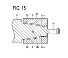
- FIG. 15 is a cross sectional view of a tool holder mounted in a holding part of a machine tool in a modified example.
- FIG. 1 is a front view of a tool holder 10 of a first embodiment.
- FIG. 2 is a left side view of the holder 10 viewed in the direction of an arrow A in FIG. 1 .
- FIG. 3 is a right side view of the same viewed in the direction of an arrow B in FIG. 1 .
- FIG. 13 is a cross sectional view showing a state where the holder 10 is mounted in a tool-holder holding part 31 (hereinafter, also referred to as a “holding part 31 ”) of a machine tool.
- a tool-holder holding part 31 hereinafter, also referred to as a “holding part 31 ”
- the tool holder 10 includes a coupling part 15 which is fitted in the holding part 31 to couple the tool holder 10 to the machine tool.
- the coupling part 15 has an inclination surface (a tapered surface) 15 a to be fitted in the holding part 31 .
- the coupling part 15 is connected, at a right end thereof, to a pull part 16 .
- this pull part 16 is grasped and pulled rightward in FIG. 1 by a pulling means (not shown) of the holding part of the machine tool, as shown in FIG. 13 , the tool holder 10 is fitted in the holding part 31 with the tapered surface 15 a being in close contact with an inner inclination portion (a tapered portion) 31 a of the holding part 31 .
- This close fitting allows the tool holder 10 to be positioned in place with respect to the holding part 31 of the machine tool. Simultaneously, by a friction force resulting from the contact surface pressure between the tapered surface 15 a and the tapered portion 31 a , machining rotation torque is transmitted from the holding part 31 to the tool holder 10 .
- the coupling part 15 is integrally connected, at a left end thereof, to a holder main body 11 .
- a tool 12 is connected to a left end of the holder main body 11 .
- the tool 12 has a distal end formed with a tip attachment member 14 .
- the tool 12 is mountable and dismountable with respect to the holder main body 11 . While the tool 12 is mounted to the main body 11 , the tool 12 and the main body 11 constantly remain in the same positional relationship in a rotation direction.
- a hexagonal spanner retainer 18 is formed on the periphery of the left end of the main body 11 .
- a throwaway tip 13 serving as a cutting blade is detachably attached.
- This throwaway tip 13 is a triangular tip easy to replace, commercially available, and widely usable in machine tools.
- a line joining a cutting edge S of the throwaway tip 13 and a central axis of the holder main body 11 is assumed to be a cutting-edge position SL.
- the positional relationship between the tool 12 and the holder main body 11 is always constant. Accordingly, the position of the cutting edge S of the throwaway tip 13 in the rotation direction constantly remains unchanged with respect to the holder main body 11 and the coupling part 15 .
- the coupling part 15 is formed, on the outer periphery, with cutouts 17 (flat surfaces in this embodiment) to provide foreign-matter receiving clearances.
- the cutouts 17 are located in a range of +30° to ⁇ 30° from the cutting-edge position SL and in a range of 150° or more to 210° or less from the cutting-edge position SL.
- FIG. 13 when the tool holder 10 is mounted in the holding part 31 , each cutout 17 and the holding part 31 define a clearance (a space) 9 for receiving foreign matters.
- Each cutout 17 is formed by chamfering the coupling part 15 with a milling machine or the like.
- the present inventors performed an experiment about the influence of the foreign matters caught between the tapered surface 15 a of the tool holder 10 and the tapered portion 31 a of the holding part 31 on machining accuracy of the machine tool.
- FIG. 7 shows experimental conditions.
- An adhesive tape 40 which is 2 mm in width and 12 mm in length, was stuck at a predetermined angular position on the tapered surface 15 a of the tool holder 10 .
- the predetermined angular position was changed to different angles relative to the cutting-edge position SL.
- the adhesive tape 40 was stuck to be centered at the predetermined angular position.
- As the adhesive tape 40 two kinds of tape were prepared; one having a thickness of 10 ⁇ m and the other having a thickness of 50 ⁇ m. After the experiments using the adhesive tape 40 , it was found that the state of the adhesive tape 40 was unchanged before and after the experiments.
- the experiments were implemented under three conditions: (1) No adhesive tape; (2) With the adhesive tape 40 having a thickness of 10 ⁇ m; and (3) With the adhesive tape 40 having a thickness of 50 ⁇ m.
- the experiments were conducted by changing the position of the adhesive tape 40 in steps of 30° from the cutting-edge position SL.
- a hole machining work was actually performed and the inside diameter of a machined hole was measured in an X-direction and a Y-direction.
- the X-direction and the Y-direction intersect each other and are adopted irrespective of the cutting-edge position.
- FIG. 8 is a graph showing data measured in the X-direction.
- FIG. 9 is a graph showing data measured in the Y-direction.
- a vertical axis represents inside diameter errors of the machined holes in units of ⁇ m.
- a permissible error (tolerance) of the inside diameter for a hole is a range of 0 to plus several tens ⁇ m.
- Measurement in the two X- and Y-directions is made in consideration of the case of machining a hole in an elliptic shape.
- a lateral axis represents positional angles of the adhesive tape 40 from the cutting-edge position SL.
- the lines S 1 and S 4 represent data resulting from the use of the adhesive tape 40 having a thickness of 50 ⁇ m.
- the lines S 2 and S 5 represent data resulting from the use of the adhesive tape 40 having a thickness of 10 ⁇ m.
- the lines S 3 and S 6 represent data resulting from the nonuse of the adhesive tape 40 .
- the diameter errors of the machined holes are negative, which are outside the standard range, as indicated by the line S 1 .
- the diameter errors are 0 to 22 ⁇ m, which falls within the standard range.
- the diameter error is 22 ⁇ m or more, which is outside the standard range.
- the diameter errors of the machined holes are negative, falling outside the standard range, as indicated by the line S 2 .
- the diameter errors are 0 to 22 ⁇ m which fall within the standard range.
- the diameter error is 22 ⁇ m which is outside the standard range.
- the diameter errors are negative, falling outside the standard range, as indicated by the line S 4 .
- the diameter errors are between 0 to +22 ⁇ m, falling within the standard range.
- the diameter errors are 22 ⁇ m or larger, which falls outside the standard range.
- the diameter errors are +22 ⁇ m or less, falling within the standard range, as indicated by the line S 5 .
- the diameter errors are 22 ⁇ m or larger, which falls outside the standard range.
- the cutting-edge position SL of the cutting edge S of the throwaway tip 13 is assumed to be an original point.
- foreign matters e.g. foreign matters each having a thickness of 10 ⁇ m or 50 ⁇ m
- the accuracy error of 20 ⁇ m or more was found in the products.
- a contact area of the tapered surface 15 a and the tapered portion 31 a is 89.5% as compared with the case where no foreign-matter receiving clearance 9 is provided. This corresponds to a reduction of 10.5% of the contact area, but the rigidity is not practically problematic.
- the tool holder fixing structure of the present embodiment is arranged to fix the tool holder 10 for holding the tool 12 attached with the throwaway tip 13 to the tool-holder holding part 31 of the machine tool and the foreign-matter receiving clearances 9 are formed between the tool holder 10 and the holding part 31 . Furthermore, the clearances 9 are formed in the circumferential range of +30° to ⁇ 30° from the cutting-edge position SL of the throwaway tip 13 assumed as the original point and in the circumferential range of 150° or more and 210° or less from the cutting-edge position SL, respectively.
- the second embodiment is substantially the same in structure as the first embodiment excepting the shape of a cutout defining a foreign-matter receiving clearance. Accordingly, the following explanation will be made with a focus on differences from the first embodiment without repeating explanations about the same parts or components.
- FIG. 4 is a front view of a tool holder 10 of the second embodiment. A left side view thereof is the same as FIG. 2 and hence is omitted.
- FIG. 5 is a cross sectional view of the tool holder 10 taken along a line M-M in FIG. 4 and FIG. 6 is a cross sectional view of the same taken along a line N-N in FIG. 4 .
- cutouts 19 for receiving foreign matters are each formed at a center of the tapered surface 15 a of the coupling part 15 in the axis direction thereof. Since each cutout 19 is formed at the center of the tapered surface, the tapered surface 15 a and the tapered portion 31 a contact each other on both sides of each cutout 19 in the axis direction.
- the tool holder 10 can have high rigidity.
- the cutouts 19 are formed in a circumferential range of +30° to ⁇ 30° from the cutting-edge position SL and in a circumferential range of 150° or more and 210° or less from the cutting-edge position SL.
- FIG. 14 is a cross sectional view showing a state where the tool holder 10 is mounted in the tool-holder holding part 31 .
- the coupling part 15 has a tapered surface 15 a to be fitted in the tool-holder holding part 31 of the machine tool.
- the coupling part 15 is connected, at its right end, to a pull part 16 .
- this pull part 16 is grasped and pulled rightward in FIG. 4 by a pulling means (not shown) of the holding part 31 , as shown in FIG. 14 , the tool holder 10 is fitted in the holding part 31 with the tapered surface 15 a being in close contact with a tapered portion 31 a .
- This close fitting allows the tool holder 10 to be positioned in place with respect to the holding part 31 .
- machining rotation torque is transmitted from the holding part 31 to the tool holder 10 .
- each foreign-matter receiving clearance 9 is defined by the tapered surface 15 a and the tapered portion 31 a around the center thereof in the axis direction. Since the tapered surface 15 a and the tapered portion 31 a are in contact with each other on both sides of each clearance 9 , the tool holder 10 can have high rigidity.
- the rigidity of cutting edge of the throwaway tip 13 is an important consideration. As to the rigidity, therefore, simulation analysis was made. Specifically, this analysis was performed by applying a predetermined load (100 N) to the cutting edge of the throwaway tip 13 from the side while the tool holder 10 is fixed to the holder holding part 31 and measuring a maximum displacement amount of the cutting edge S. In the case where no cutout 19 is formed, the maximum displacement amount was 0.35 mm.
- the maximum displacement amount was 0.35 mm.
- the maximum displacement amount was unchanged.
- a contact area of the tapered surface 15 a and the tapered portion 31 a is 73.6% as compared with the case where no foreign-matter receiving clearance 9 is provided. This corresponds to a reduction of 26.4% of the contact area, but the rigidity is not practically problematic.
- the tool holder fixing structure of the second embodiment is arranged to fix the tool holder 10 for holding the tool 12 attached with the throwaway tip 13 to the tool-holder holding part 31 of the machine tool and the foreign-matter receiving clearances 9 are formed between the tool holder 10 and the holding part 31 .
- the clearances 9 are formed in the circumferential range of +30° to ⁇ 30° from the cutting-edge position SL of the throwaway tip 13 assumed as the original point and in the circumferential range of 150° or more and 210° or less from the cutting-edge position SL, respectively.
- each clearance 9 is formed at the center of the contact surfaces of the tool holder 10 and the holding part 31 .
- the contact relation between the tapered surface 15 a of the tool holder 10 and the tapered portion 31 a of the tool-holder holding part 31 can be maintained on both ends of the contact surface (on both sides of each clearance 9 ). Accordingly, the tool holder 10 can have high rigidity. Even when the foreign matters enter between the tapered surface 15 a of the tool holder 10 and the tapered portion 31 a of the tool-holder holding part 31 , the foreign matters entering in the circumferential range of +30° to ⁇ 30° from the cutting-edge position SL and in the circumferential range of 150° to 210° from the cutting-edge position SL will be received in the foreign-matter receiving clearances 9 . Thus, the foreign matters are unlikely to affect the machining accuracy of the throwaway tip 13 .
- the third embodiment differs from the first embodiment in the shape of a tool holder and the shape of a cutout for forming a foreign-matter receiving clearance.
- the following explanation is therefore made with a focus on differences without repeating explanations of similar parts or components to those in the first embodiment.
- FIG. 10 is a front view of a tool holder 100 of the third embodiment.
- FIG. 11 is a side view of the same as viewed in the direction of an arrow C in FIG. 10
- FIG. 12 is a side view of the same as viewed in the direction of an arrow D in FIG. 10 .
- the tool holder 100 in FIG. 10 is used for machining a large-diameter hole.
- This tool holder 100 includes a tool attachment part 21 formed in an angular U shape having two extended ends and the one end 22 thereof is removably attached with a throwaway tip 13 with a retainer 22 a .
- the tool attachment part 21 is integrally connected, at a right end thereof, to a holder main body 23 formed with a coupling part 24 at a right end.
- the holder main body 23 and the coupling part 24 are shown in vertical cross-section.
- the coupling part 24 is formed, on its outer periphery, with cutouts 25 for defining foreign-matter receiving clearances.
- the tool attachment part 21 is omitted for convenience.
- SL denotes a cutting-edge position of the throwaway tip 13 .
- the cutouts 25 are formed in a circumferential range of +30° to ⁇ 30° on both sides of the cutting-edge position SL and in a circumferential range of 150° or more and 210° or less from the cutting-edge position SL, respectively.
- the present invention can be applied to the tool holder 100 with the throwaway tip 13 for machining large-diameter hole.
- the cutouts 17 , 19 , and 25 for foreign-matter receiving clearances are formed in the tapered surface 15 a of the tool holder 10 .
- the tapered portion 31 a of the tool-holder holding part 31 may be formed with cutouts 32 for providing clearances to receive foreign matters.
- the cutting-edge position SL of the throwaway tip 13 of the tool holder 10 has to be aligned with the tool-holder holding part 31 of the machine tool.
- alignment work is not problematic when the tool holder 10 is mounted or dismounted with respect to the holding part 31 by use of robots.
- the foreign-matter receiving clearances are formed in the circumferential range of +30° and ⁇ 30° from the cutting-edge position of the throwaway tip assumed as the original point and in the circumferential range of 150° to 210° from the original point.
- Those angular ranges may be reduced to a circumferential range of +20° and ⁇ 20° from the original point and a circumferential range of 160° or more and 200° or less from the original point.
- This configuration can enhance rigidity even though it may increase a risk of causing foreign matters to be caught.
- the above embodiments are explained about the tool holder attached with the throwaway tip.
- the present invention may also be applied to a tool to which a cutting edge is fixed by brazing or a tool such as an end mill.
- the configurations of the aforementioned first and second embodiments may be applied to a double hit holder, for example, HS, HSK, NC5, KM, BIG PLUS, BTS.
Landscapes
- Engineering & Computer Science (AREA)
- Mechanical Engineering (AREA)
- Jigs For Machine Tools (AREA)
- Gripping On Spindles (AREA)
Abstract
Description
- Patent Literature 1: JP2006-334676A
- 9 Foreign-matter receiving clearance
- 10 Tool holder
- 13 Throwaway tip
- 15 Coupling part
- 15 a Tapered surface
- 17, 19 Cutout for foreign-matter receiving clearance
- 31 Tool-holder holding part
- 31 a Tapered portion
- S Cutting edge
- SL Cutting-edge position
Claims (5)
Applications Claiming Priority (3)
| Application Number | Priority Date | Filing Date | Title |
|---|---|---|---|
| JP2008116093A JP4930450B2 (en) | 2008-04-25 | 2008-04-25 | Tool holder fixing structure |
| JP2008-116093 | 2008-04-25 | ||
| PCT/JP2009/057627 WO2009131049A1 (en) | 2008-04-25 | 2009-04-09 | Tool holder fixing structure |
Publications (2)
| Publication Number | Publication Date |
|---|---|
| US20110038680A1 US20110038680A1 (en) | 2011-02-17 |
| US8702358B2 true US8702358B2 (en) | 2014-04-22 |
Family
ID=40750842
Family Applications (1)
| Application Number | Title | Priority Date | Filing Date |
|---|---|---|---|
| US12/988,953 Active 2031-05-06 US8702358B2 (en) | 2008-04-25 | 2009-04-09 | Tool holder fixing structure |
Country Status (4)
| Country | Link |
|---|---|
| US (1) | US8702358B2 (en) |
| EP (1) | EP2285514B1 (en) |
| JP (1) | JP4930450B2 (en) |
| WO (1) | WO2009131049A1 (en) |
Families Citing this family (2)
| Publication number | Priority date | Publication date | Assignee | Title |
|---|---|---|---|---|
| CN107617917A (en) * | 2017-10-27 | 2018-01-23 | 东莞市显隆电机有限公司 | A kind of broaching tool of high-speed electric main shaft HSK handle of a knifes |
| EP4008460A1 (en) * | 2020-12-04 | 2022-06-08 | Laip, S.A. | Precision thermal modular toolholder |
Citations (7)
| Publication number | Priority date | Publication date | Assignee | Title |
|---|---|---|---|---|
| US4723877A (en) * | 1987-01-27 | 1988-02-09 | Kennametal Inc. | Toolholder |
| JPH06226515A (en) | 1993-01-29 | 1994-08-16 | Hitachi Seiko Ltd | Spindle of machine tool |
| JPH08281528A (en) | 1995-04-11 | 1996-10-29 | Daishowa Seiki Co Ltd | Taper sleeve |
| DE29809653U1 (en) * | 1998-05-29 | 1998-08-13 | Marciniak, Heinz, 58455 Witten | Tool holder, especially for milling tools |
| US20050158135A1 (en) * | 2004-01-21 | 2005-07-21 | Massa Ted R. | Tool holder |
| JP2006334676A (en) | 2005-05-31 | 2006-12-14 | Denso Corp | Machine tool, foreign matter removing method and foreign matter detecting method |
| US8348560B1 (en) * | 2008-09-18 | 2013-01-08 | Variable Operations Technologies, Inc. | Tool head for a machine tool |
-
2008
- 2008-04-25 JP JP2008116093A patent/JP4930450B2/en not_active Expired - Fee Related
-
2009
- 2009-04-09 EP EP09734951A patent/EP2285514B1/en not_active Not-in-force
- 2009-04-09 WO PCT/JP2009/057627 patent/WO2009131049A1/en not_active Ceased
- 2009-04-09 US US12/988,953 patent/US8702358B2/en active Active
Patent Citations (10)
| Publication number | Priority date | Publication date | Assignee | Title |
|---|---|---|---|---|
| US4723877A (en) * | 1987-01-27 | 1988-02-09 | Kennametal Inc. | Toolholder |
| JPS6487107A (en) | 1987-01-27 | 1989-03-31 | Kennametal Inc | Tool holder |
| JPH06226515A (en) | 1993-01-29 | 1994-08-16 | Hitachi Seiko Ltd | Spindle of machine tool |
| JPH08281528A (en) | 1995-04-11 | 1996-10-29 | Daishowa Seiki Co Ltd | Taper sleeve |
| DE29809653U1 (en) * | 1998-05-29 | 1998-08-13 | Marciniak, Heinz, 58455 Witten | Tool holder, especially for milling tools |
| US20050158135A1 (en) * | 2004-01-21 | 2005-07-21 | Massa Ted R. | Tool holder |
| WO2005072210A2 (en) | 2004-01-21 | 2005-08-11 | Kennametal Inc. | Tool holder |
| JP2007518585A (en) | 2004-01-21 | 2007-07-12 | ケンナメタル インコーポレイテッド | Tool holder |
| JP2006334676A (en) | 2005-05-31 | 2006-12-14 | Denso Corp | Machine tool, foreign matter removing method and foreign matter detecting method |
| US8348560B1 (en) * | 2008-09-18 | 2013-01-08 | Variable Operations Technologies, Inc. | Tool head for a machine tool |
Also Published As
| Publication number | Publication date |
|---|---|
| WO2009131049A1 (en) | 2009-10-29 |
| EP2285514A1 (en) | 2011-02-23 |
| EP2285514B1 (en) | 2012-08-08 |
| US20110038680A1 (en) | 2011-02-17 |
| JP2009262292A (en) | 2009-11-12 |
| JP4930450B2 (en) | 2012-05-16 |
Similar Documents
| Publication | Publication Date | Title |
|---|---|---|
| US9211597B2 (en) | Cutting tool and cutting insert for the same | |
| US7341409B2 (en) | Tool for chip removing machining | |
| KR101064639B1 (en) | Cutting inserts and cutting tools including the same | |
| US8534963B2 (en) | Tool for machining a workpiece | |
| US8262072B2 (en) | Work piece carrier for exactly positioning a work piece on a chuck and clamping apparatus with a chuck and a work piece carrier | |
| KR102202451B1 (en) | Coupling mechanism for cutting tool | |
| JP6790335B2 (en) | Cutting tools | |
| US8950985B2 (en) | Rotating tool | |
| SE1450566A1 (en) | Coupling part, especially cutting head for a rotating tool, one with this complementary coupling part and rotating tool | |
| US20140169896A1 (en) | Metal-Cutting Tool, In Particular Reaming Tool | |
| US8702358B2 (en) | Tool holder fixing structure | |
| JP2007216378A (en) | Blade changing type cutting tool | |
| US8668411B2 (en) | Cutting tool and holder | |
| US20110064529A1 (en) | Cutting Tool and Holder | |
| JP2012510376A (en) | Milling coupling system | |
| JP2013504444A (en) | Reamer for cutting workpieces | |
| TW202402428A (en) | Tool holder having a cylindrical fixation bore extending rearwardly from a front fixation surface and a fastening bore intersecting the front fixation surface | |
| US20200030894A1 (en) | Drilling Tool Comprising A Replaceable Cutting Disk | |
| JP5428997B2 (en) | Cutting tool with replaceable cutting edge | |
| US20240100604A1 (en) | Cutting insert, holder, and blade-tip-replaceable cutting tool | |
| JP5882822B2 (en) | Fixed member and cutting tool | |
| US8240960B2 (en) | Device for producing precise countersinking in drilled holes | |
| JP5544976B2 (en) | Cutting tool with replaceable cutting edge | |
| WO2021206147A1 (en) | Tool-holding structure, load detection structure, and tool-state-monitoring system | |
| CN113547172B (en) | A high-precision double-end cutting combined reamer |
Legal Events
| Date | Code | Title | Description |
|---|---|---|---|
| AS | Assignment |
Owner name: FUJI SEIKO LIMITED, JAPAN Free format text: ASSIGNMENT OF ASSIGNORS INTEREST;ASSIGNORS:YAMADA, KOJI;KAMIKUBO, TOSHITAKA;SHIGA, KIYOTAKA;AND OTHERS;REEL/FRAME:025174/0973 Effective date: 20100908 Owner name: TOYOTA JIDOSHA KABUSHIKI KAISHA, JAPAN Free format text: ASSIGNMENT OF ASSIGNORS INTEREST;ASSIGNORS:YAMADA, KOJI;KAMIKUBO, TOSHITAKA;SHIGA, KIYOTAKA;AND OTHERS;REEL/FRAME:025174/0973 Effective date: 20100908 |
|
| AS | Assignment |
Owner name: TOYOTA JIDOSHA KABUSHIKI KAISHA, JAPAN Free format text: ASSIGNMENT OF ASSIGNORS INTEREST;ASSIGNORS:FUJI SEIKO LIMITED;TOYOTA JIDOSHA KABUSHIKI KAISHA;SIGNING DATES FROM 20110301 TO 20110309;REEL/FRAME:025983/0202 |
|
| STCF | Information on status: patent grant |
Free format text: PATENTED CASE |
|
| FEPP | Fee payment procedure |
Free format text: PAYOR NUMBER ASSIGNED (ORIGINAL EVENT CODE: ASPN); ENTITY STATUS OF PATENT OWNER: LARGE ENTITY |
|
| MAFP | Maintenance fee payment |
Free format text: PAYMENT OF MAINTENANCE FEE, 4TH YEAR, LARGE ENTITY (ORIGINAL EVENT CODE: M1551) Year of fee payment: 4 |
|
| MAFP | Maintenance fee payment |
Free format text: PAYMENT OF MAINTENANCE FEE, 8TH YEAR, LARGE ENTITY (ORIGINAL EVENT CODE: M1552); ENTITY STATUS OF PATENT OWNER: LARGE ENTITY Year of fee payment: 8 |
|
| FEPP | Fee payment procedure |
Free format text: MAINTENANCE FEE REMINDER MAILED (ORIGINAL EVENT CODE: REM.); ENTITY STATUS OF PATENT OWNER: LARGE ENTITY |