US8700360B2 - System and method for monitoring and detecting faults in a closed-loop system - Google Patents
System and method for monitoring and detecting faults in a closed-loop system Download PDFInfo
- Publication number
- US8700360B2 US8700360B2 US12/983,260 US98326010A US8700360B2 US 8700360 B2 US8700360 B2 US 8700360B2 US 98326010 A US98326010 A US 98326010A US 8700360 B2 US8700360 B2 US 8700360B2
- Authority
- US
- United States
- Prior art keywords
- error signal
- tracking error
- closed
- fault
- egr
- Prior art date
- Legal status (The legal status is an assumption and is not a legal conclusion. Google has not performed a legal analysis and makes no representation as to the accuracy of the status listed.)
- Active, expires
Links
Images


Classifications
-
- F—MECHANICAL ENGINEERING; LIGHTING; HEATING; WEAPONS; BLASTING
- F02—COMBUSTION ENGINES; HOT-GAS OR COMBUSTION-PRODUCT ENGINE PLANTS
- F02D—CONTROLLING COMBUSTION ENGINES
- F02D41/00—Electrical control of supply of combustible mixture or its constituents
- F02D41/0025—Controlling engines characterised by use of non-liquid fuels, pluralities of fuels, or non-fuel substances added to the combustible mixtures
- F02D41/0047—Controlling exhaust gas recirculation [EGR]
- F02D41/0065—Specific aspects of external EGR control
- F02D41/0072—Estimating, calculating or determining the EGR rate, amount or flow
-
- G—PHYSICS
- G05—CONTROLLING; REGULATING
- G05B—CONTROL OR REGULATING SYSTEMS IN GENERAL; FUNCTIONAL ELEMENTS OF SUCH SYSTEMS; MONITORING OR TESTING ARRANGEMENTS FOR SUCH SYSTEMS OR ELEMENTS
- G05B23/00—Testing or monitoring of control systems or parts thereof
- G05B23/02—Electric testing or monitoring
- G05B23/0205—Electric testing or monitoring by means of a monitoring system capable of detecting and responding to faults
- G05B23/0218—Electric testing or monitoring by means of a monitoring system capable of detecting and responding to faults characterised by the fault detection method dealing with either existing or incipient faults
- G05B23/0221—Preprocessing measurements, e.g. data collection rate adjustment; Standardization of measurements; Time series or signal analysis, e.g. frequency analysis or wavelets; Trustworthiness of measurements; Indexes therefor; Measurements using easily measured parameters to estimate parameters difficult to measure; Virtual sensor creation; De-noising; Sensor fusion; Unconventional preprocessing inherently present in specific fault detection methods like PCA-based methods
-
- F—MECHANICAL ENGINEERING; LIGHTING; HEATING; WEAPONS; BLASTING
- F02—COMBUSTION ENGINES; HOT-GAS OR COMBUSTION-PRODUCT ENGINE PLANTS
- F02D—CONTROLLING COMBUSTION ENGINES
- F02D41/00—Electrical control of supply of combustible mixture or its constituents
- F02D41/02—Circuit arrangements for generating control signals
- F02D41/14—Introducing closed-loop corrections
- F02D41/1401—Introducing closed-loop corrections characterised by the control or regulation method
-
- F—MECHANICAL ENGINEERING; LIGHTING; HEATING; WEAPONS; BLASTING
- F02—COMBUSTION ENGINES; HOT-GAS OR COMBUSTION-PRODUCT ENGINE PLANTS
- F02D—CONTROLLING COMBUSTION ENGINES
- F02D41/00—Electrical control of supply of combustible mixture or its constituents
- F02D41/22—Safety or indicating devices for abnormal conditions
-
- F—MECHANICAL ENGINEERING; LIGHTING; HEATING; WEAPONS; BLASTING
- F02—COMBUSTION ENGINES; HOT-GAS OR COMBUSTION-PRODUCT ENGINE PLANTS
- F02M—SUPPLYING COMBUSTION ENGINES IN GENERAL WITH COMBUSTIBLE MIXTURES OR CONSTITUENTS THEREOF
- F02M26/00—Engine-pertinent apparatus for adding exhaust gases to combustion-air, main fuel or fuel-air mixture, e.g. by exhaust gas recirculation [EGR] systems
- F02M26/45—Sensors specially adapted for EGR systems
- F02M26/46—Sensors specially adapted for EGR systems for determining the characteristics of gases, e.g. composition
- F02M26/47—Sensors specially adapted for EGR systems for determining the characteristics of gases, e.g. composition the characteristics being temperatures, pressures or flow rates
-
- F—MECHANICAL ENGINEERING; LIGHTING; HEATING; WEAPONS; BLASTING
- F02—COMBUSTION ENGINES; HOT-GAS OR COMBUSTION-PRODUCT ENGINE PLANTS
- F02M—SUPPLYING COMBUSTION ENGINES IN GENERAL WITH COMBUSTIBLE MIXTURES OR CONSTITUENTS THEREOF
- F02M26/00—Engine-pertinent apparatus for adding exhaust gases to combustion-air, main fuel or fuel-air mixture, e.g. by exhaust gas recirculation [EGR] systems
- F02M26/49—Detecting, diagnosing or indicating an abnormal function of the EGR system
-
- F—MECHANICAL ENGINEERING; LIGHTING; HEATING; WEAPONS; BLASTING
- F01—MACHINES OR ENGINES IN GENERAL; ENGINE PLANTS IN GENERAL; STEAM ENGINES
- F01N—GAS-FLOW SILENCERS OR EXHAUST APPARATUS FOR MACHINES OR ENGINES IN GENERAL; GAS-FLOW SILENCERS OR EXHAUST APPARATUS FOR INTERNAL-COMBUSTION ENGINES
- F01N2900/00—Details of electrical control or of the monitoring of the exhaust gas treating apparatus
- F01N2900/04—Methods of control or diagnosing
- F01N2900/0408—Methods of control or diagnosing using a feed-back loop
-
- F—MECHANICAL ENGINEERING; LIGHTING; HEATING; WEAPONS; BLASTING
- F01—MACHINES OR ENGINES IN GENERAL; ENGINE PLANTS IN GENERAL; STEAM ENGINES
- F01N—GAS-FLOW SILENCERS OR EXHAUST APPARATUS FOR MACHINES OR ENGINES IN GENERAL; GAS-FLOW SILENCERS OR EXHAUST APPARATUS FOR INTERNAL-COMBUSTION ENGINES
- F01N2900/00—Details of electrical control or of the monitoring of the exhaust gas treating apparatus
- F01N2900/04—Methods of control or diagnosing
- F01N2900/0418—Methods of control or diagnosing using integration or an accumulated value within an elapsed period
-
- F—MECHANICAL ENGINEERING; LIGHTING; HEATING; WEAPONS; BLASTING
- F02—COMBUSTION ENGINES; HOT-GAS OR COMBUSTION-PRODUCT ENGINE PLANTS
- F02B—INTERNAL-COMBUSTION PISTON ENGINES; COMBUSTION ENGINES IN GENERAL
- F02B29/00—Engines characterised by provision for charging or scavenging not provided for in groups F02B25/00, F02B27/00 or F02B33/00 - F02B39/00; Details thereof
- F02B29/04—Cooling of air intake supply
- F02B29/0406—Layout of the intake air cooling or coolant circuit
-
- F—MECHANICAL ENGINEERING; LIGHTING; HEATING; WEAPONS; BLASTING
- F02—COMBUSTION ENGINES; HOT-GAS OR COMBUSTION-PRODUCT ENGINE PLANTS
- F02D—CONTROLLING COMBUSTION ENGINES
- F02D41/00—Electrical control of supply of combustible mixture or its constituents
- F02D41/02—Circuit arrangements for generating control signals
- F02D41/14—Introducing closed-loop corrections
- F02D41/1401—Introducing closed-loop corrections characterised by the control or regulation method
- F02D2041/1413—Controller structures or design
- F02D2041/1432—Controller structures or design the system including a filter, e.g. a low pass or high pass filter
-
- F—MECHANICAL ENGINEERING; LIGHTING; HEATING; WEAPONS; BLASTING
- F02—COMBUSTION ENGINES; HOT-GAS OR COMBUSTION-PRODUCT ENGINE PLANTS
- F02D—CONTROLLING COMBUSTION ENGINES
- F02D41/00—Electrical control of supply of combustible mixture or its constituents
- F02D41/24—Electrical control of supply of combustible mixture or its constituents characterised by the use of digital means
- F02D41/26—Electrical control of supply of combustible mixture or its constituents characterised by the use of digital means using computer, e.g. microprocessor
- F02D41/28—Interface circuits
- F02D2041/286—Interface circuits comprising means for signal processing
- F02D2041/288—Interface circuits comprising means for signal processing for performing a transformation into the frequency domain, e.g. Fourier transformation
-
- F—MECHANICAL ENGINEERING; LIGHTING; HEATING; WEAPONS; BLASTING
- F02—COMBUSTION ENGINES; HOT-GAS OR COMBUSTION-PRODUCT ENGINE PLANTS
- F02M—SUPPLYING COMBUSTION ENGINES IN GENERAL WITH COMBUSTIBLE MIXTURES OR CONSTITUENTS THEREOF
- F02M26/00—Engine-pertinent apparatus for adding exhaust gases to combustion-air, main fuel or fuel-air mixture, e.g. by exhaust gas recirculation [EGR] systems
- F02M26/02—EGR systems specially adapted for supercharged engines
- F02M26/04—EGR systems specially adapted for supercharged engines with a single turbocharger
- F02M26/05—High pressure loops, i.e. wherein recirculated exhaust gas is taken out from the exhaust system upstream of the turbine and reintroduced into the intake system downstream of the compressor
-
- F—MECHANICAL ENGINEERING; LIGHTING; HEATING; WEAPONS; BLASTING
- F02—COMBUSTION ENGINES; HOT-GAS OR COMBUSTION-PRODUCT ENGINE PLANTS
- F02M—SUPPLYING COMBUSTION ENGINES IN GENERAL WITH COMBUSTIBLE MIXTURES OR CONSTITUENTS THEREOF
- F02M26/00—Engine-pertinent apparatus for adding exhaust gases to combustion-air, main fuel or fuel-air mixture, e.g. by exhaust gas recirculation [EGR] systems
- F02M26/13—Arrangement or layout of EGR passages, e.g. in relation to specific engine parts or for incorporation of accessories
- F02M26/22—Arrangement or layout of EGR passages, e.g. in relation to specific engine parts or for incorporation of accessories with coolers in the recirculation passage
- F02M26/23—Layout, e.g. schematics
-
- G—PHYSICS
- G01—MEASURING; TESTING
- G01M—TESTING STATIC OR DYNAMIC BALANCE OF MACHINES OR STRUCTURES; TESTING OF STRUCTURES OR APPARATUS, NOT OTHERWISE PROVIDED FOR
- G01M15/00—Testing of engines
- G01M15/04—Testing internal-combustion engines
- G01M15/10—Testing internal-combustion engines by monitoring exhaust gases or combustion flame
-
- G—PHYSICS
- G01—MEASURING; TESTING
- G01R—MEASURING ELECTRIC VARIABLES; MEASURING MAGNETIC VARIABLES
- G01R23/00—Arrangements for measuring frequencies; Arrangements for analysing frequency spectra
- G01R23/16—Spectrum analysis; Fourier analysis
- G01R23/165—Spectrum analysis; Fourier analysis using filters
-
- G—PHYSICS
- G05—CONTROLLING; REGULATING
- G05B—CONTROL OR REGULATING SYSTEMS IN GENERAL; FUNCTIONAL ELEMENTS OF SUCH SYSTEMS; MONITORING OR TESTING ARRANGEMENTS FOR SUCH SYSTEMS OR ELEMENTS
- G05B23/00—Testing or monitoring of control systems or parts thereof
- G05B23/02—Electric testing or monitoring
- G05B23/0205—Electric testing or monitoring by means of a monitoring system capable of detecting and responding to faults
- G05B23/0218—Electric testing or monitoring by means of a monitoring system capable of detecting and responding to faults characterised by the fault detection method dealing with either existing or incipient faults
-
- Y—GENERAL TAGGING OF NEW TECHNOLOGICAL DEVELOPMENTS; GENERAL TAGGING OF CROSS-SECTIONAL TECHNOLOGIES SPANNING OVER SEVERAL SECTIONS OF THE IPC; TECHNICAL SUBJECTS COVERED BY FORMER USPC CROSS-REFERENCE ART COLLECTIONS [XRACs] AND DIGESTS
- Y02—TECHNOLOGIES OR APPLICATIONS FOR MITIGATION OR ADAPTATION AGAINST CLIMATE CHANGE
- Y02T—CLIMATE CHANGE MITIGATION TECHNOLOGIES RELATED TO TRANSPORTATION
- Y02T10/00—Road transport of goods or passengers
- Y02T10/10—Internal combustion engine [ICE] based vehicles
- Y02T10/40—Engine management systems
Definitions
- the invention relates to monitoring a closed-loop system, such as an exhaust gas recirculation (EGR) system, having a controlled variable, and in particular, to a system and method for monitoring a closed-loop system for variation in performance and system fault detection based on the closed-loop system performance variation.
- EGR exhaust gas recirculation
- Emissions targets for 2010 and beyond require the use of extreme high fidelity EGR flow measurement to control NOx during engine transients, as well as to provide precise measurement of EGR flow resulting from exhaust manifold pulsations.
- the air-handling system is tightly controlled so as to obtain the commanded amount of EGR which is determined by the combustion recipe.
- the presence of a fault in the EGR handling system e.g., a restriction, a leak or a faulty sensor/actuator
- the inventions are directed to a system, method and internal combustion engine system that monitors a closed-loop system having a controllable variable to detect the off-nominal behavior of the system and raising an alarm or other alerting mechanism when fault is detected.
- a method of detecting fault in a closed-loop system includes monitoring a tracking error signal indicative of a difference between a reference value of a variable of the closed-loop system to be controlled and a measured value of the variable being controlled, filtering the tracking error signal to isolate a band of frequency components impacted by deviation in the tracking error signal caused by a fault to be detected, and generating an accumulated error signal from the filtered tracking error signal.
- the accumulated error signal is compared with a predetermined fault threshold characteristic, and if the accumulated error signal meets the predetermined threshold an indicator of fault is provided for the closed-loop system.
- a system for monitoring a tracking error signal indicative of a difference between a reference value of a variable of the closed-loop system to be controlled and a measured value of the variable being controlled and detecting faults in a closed-loop system.
- the system includes a first filter module adapted to receive the tracking error signal and filter the tracking error signal to isolate a band of frequency components impacted by deviation in the tracking error signal caused by a fault to be detected.
- a second filter module is communicatively coupled with the first filter module and is adapted to receive the filtered tracking error signal and generate an accumulated error signal from the filtered tracking error signal.
- a fault processing module is communicatively coupled with the second filter module and is adapted to receive the accumulated error signal and compare the accumulated error signal with a stored predetermined fault threshold characteristic and provide an indicator of a fault in the closed-loop system if the accumulated error signal meets the predetermined fault threshold characteristic.
- an internal combustion engine system including an engine, an intake manifold connected to the engine, an intake body fluidly connected to the intake manifold and including a chamber through which charge air flows, an exhaust manifold connected to the engine, and an exhaust gas recirculation (EGR) passage fluidly connected at one end thereof to the exhaust manifold and at another end thereof to the chamber of the intake body.
- EGR exhaust gas recirculation
- exhaust gas flow is controlled by an EGR closed-loop system as a function of an exhaust flow tracking error signal, and the engine system includes a monitor for detecting faults in the EGR closed-loop system.
- the monitor includes a first filter element that receives the exhaust tracking error signal and filters the tracking error signal to isolate a band of frequency components impacted by deviation in the error signal caused by a fault to be detected and provide a filtered tracking error signal having the isolated frequency band.
- a second filter element is communicatively coupled with the first filter element and adapted to receive the filtered tracking error signal and generate an accumulated error signal from the filtered tracking error signal.
- a fault processing element is communicatively coupled with the second filter element and adapted to receive the accumulated error signal, compare the accumulated error signal with a stored predetermined fault threshold characteristic, and provide an indicator of fault in the closed-loop system if the accumulated error signal meets the predetermined threshold.
- FIG. 1 is a diagram of an internal combustion engine system including a closed-loop EGR control system and EGR system monitoring system according to an exemplary embodiment.
- FIG. 2 is a block diagram of relevant parameters of an EGR system monitor algorithm according to an exemplary embodiment.
- FIG. 3 is a block diagram of an exemplary closed-loop system with a plant.
- FIG. 4 is a graph of the power spectral density of an EGR flow tracking error for nominal and failed EGR systems.
- FIG. 5 is a diagram of an exemplary EGR system monitor modules and logic flow according to an exemplary embodiment.
- FIG. 6A is a graph showing an unfiltered EGR flow tracking error signal of a healthy engine during an FTP run.
- FIG. 6B is a graph showing a low pass filtered version of the EGR flow tracking error signal shown in FIG. 6A .
- FIG. 6C is a graph showing an unfiltered EGR flow tracking error signal of a failed engine during an FTP run.
- FIG. 6D is a graph showing a low pass filtered version of the EGR flow tracking error signal shown in FIG. 6C .
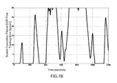
- FIG. 7A is a graph of scaled cumulative filtered EGR flow error of the flow tracking error shown in FIG. 6B .
- FIG. 7B is a graph of scaled cumulative filtered EGR flow error of the flow tracking error shown in FIG. 6D .
- FIG. 8A is a flow chart of a method of modeling response of a closed-loop system to a fault according to an exemplary embodiment.
- FIG. 8B is a flow chart of a method of detecting a fault in a closed-loop system according to an exemplary embodiment.
- FIG. 1 is a diagram of an internal combustion engine system 1 that includes an EGR system monitor according to an exemplary embodiment.
- the internal combustion engine system 1 includes a first fluid communication path between an intake manifold 12 and an exhaust manifold 14 through an internal combustion engine 10 ; and a second fluid communication path included in an EGR loop between the intake manifold 12 and the exhaust manifold 14 .
- a controller 15 controlling and monitoring various elements of engine system 1 and includes an EGR system monitor (SM) 16 .
- SM EGR system monitor
- Fresh air is provided to the intake manifold 12 .
- a compressor 17 which is mechanically driven by a turbine 18 fluidly connected to the exhaust manifold 14 , receives the fresh air at ambient temperature and pressure from a fresh air inlet 20 , compresses that air, and the compressed fresh air mass flow rate (FAF) flows to a charge air cooler (CAC) 22 provided downstream of the compressor 17 .
- An intake throttle 24 is positioned downstream of the CAC 22 and is operable to control the flow of fresh air via an actuator (not shown) that is controlled by the controller 15 via signal path 34 .
- the intake manifold 12 is connected to an intake body including a chamber, or mixer 26 that is fluidly coupled between the intake throttle 24 and the intake manifold 12 to mix air from the compressor 17 and EGR gas to provide charge air to the intake manifold 12 .
- Fuel is injected into either the intake manifold or directly into the cylinders of the engine 10 , where it is combusted with the charge air.
- the exhaust manifold 14 is fluidly connected to the cylinders to received exhaust gas produced during combustion of charge air and fuel in the cylinder.
- the turbine 18 is fluidly connected downstream of the exhaust manifold 14 and the exhaust gas mass flow (M air +M fuel ) at pressure PEM and temperature TEM enters the turbine 18 .
- the turbine 18 includes an actuator (not shown) that is operable to alter its efficiency or operational range under the control of the controller 15 via signal path 36 .
- the turbine 18 can be a VGT (variable geometry turbocharger), which allows altering the orientation of vanes in the turbine based on a position of an actuator (e.g., an electric, pneumatic and/or hydraulic actuator) to supply sufficient boost at all engine speeds and ensure a specified ratio of EGR gas recirculated back to the engine intake manifold 12 .
- the exhaust gas exiting the turbine 18 enters conduit 28 and is provided to an exhaust after-treatment (AT) system 29 before exiting through an exhaust pipe 30 to the ambient environment.
- the turbine 18 can be a multi-staged turbocharger (e.g., a high pressure turbine fluidly connected to a low pressure turbine) operating in series or sequential mode.
- the EGR loop starts at the exhaust manifold 14 where exhaust gas enters a passage that can include an EGR cooler 31 and EGR control valve 32 .
- the EGR control valve 32 is operable to control how much and when exhaust gas mass flow MEGR flows into the mixer 26 where it is mixed with compressed air supplied by the compressor 17 .
- the EGR control valve 32 is controlled to provide an MEGR value corresponding to an EGR mass flow command based on an operating mode or condition.
- the EGR control valve 32 is generally partially closed or closed at idle, high, and low operating speeds.
- the position of the EGR valve 32 is controlled by the controller 15 via a signal along signal path 38 .
- the controller 15 can be an electronic control unit (ECU) or electronic control module (ECM), or one or more controllers separate from, but in communication with an ECU/ECM.
- the controller 15 can include a processor and modules in the form of software or routines that are stored on computer readable media such as memory (not shown), which are executable by the processor of the control module.
- modules of control module 15 can include electronic circuits for performing some or all or part of the processing, including analog and/or digital circuitry.
- the modules can comprise a combination of software, electronic circuits and microprocessor based components.
- the controller 15 can receive data regarding requested power, data indicative of engine performance, exhaust gas composition including, but not limited to engine position sensor data; engine speed sensor data (rpm); vehicle speed data (mph), exhaust mass flow sensor data, fuel rate data, intake manifold pressure (IMP) data, EGR pressure (P egr ), and other pressure sensor data; intake manifold temperature (IMT) data, EGR gas temperature (T egr ) data, and other temperature sensor data from locations throughout the engine 10 ; data from various parts of the exhaust after-treatment system 29 (e.g., pressures and temperatures of DPF, SCR, DOC and/or other AT elements), and other data.
- exhaust gas composition including, but not limited to engine position sensor data; engine speed sensor data (rpm); vehicle speed data (mph), exhaust mass flow sensor data, fuel rate data, intake manifold pressure (IMP) data, EGR pressure (P egr ), and other pressure sensor data; intake manifold temperature (IMT) data, EGR gas temperature (T egr ) data, and
- the controller 15 can then generate control signals and output these signals to control the fuel injectors of a high pressure fuel system (not shown) to inject a metered amount of fuel either directly into the engine cylinders or indirectly (e.g., into the intake manifold 12 ) to operate within either a lean burn condition or a stoichiometric condition, depending on the engine load or other conditions.
- the controller 15 can determine an air flow command (M FAF— cmd), charge flow command (MCF_cmd), fueling amount, injection timing etc. in response to a requested engine speed and load, and set various actuator devices in the engine system including the actuators of the engine system 1 to achieve the requested speed and load.
- the vehicle or system OBD e.g., OBD-II or HD-OBD
- the vehicle or system OBD can include an interface (not shown) that can access the ECU/ECM to obtain the status of the EGR system and numerous other data for monitoring and detecting emissions related issues.
- FIG. 2 shows the relevant parameters of an exemplary embodiment of an EGR SM 16 algorithm, which can be implemented in software and/or hardware.
- the algorithm generates as outputs one or more status indicators related to the performance of the EGR system.
- the input parameters to the EGR SM 16 can include input signals 40 , control factors 42 , and noise factors 44 .
- the EGR SM 16 determines outputs 46 related to whether EGR flow to the intake is sufficient and/or the EGR system response is slower than a nominal value, and perhaps other information related to the EGR system.
- the input signals 40 to the EGR SM 16 can include the engine's speed (rpm), total fueling (mg/stroke), the engine operating condition in the form of the engine speed-fueling points that determine the air-handling references, measured EGR flow rate M EGR (kg/min) (e.g., via delta-P measurement, P egr , T egr , IMP, IMT and FAF), air-handling references (kg/min) (e.g., commanded EGR flow (M EGR— cmd), commanded charge air flow rate (MCF_cmd), and commanded fresh air flow rate (M FAF— cmd), an enable flag that represents the fact that all prescribed enable conditions have been satisfied and the algorithm should start execution.
- M EGR commanded EGR flow
- MMF_cmd commanded charge air flow rate
- M FAF— cmd commanded fresh air flow rate
- the control factors 42 can include the digital filter cutoff frequency ⁇ cutoff , filter design constraints, sampling frequency, run frequency, moving average filter bleed factor, and cumulative sum (cusum) threshold factor.
- the noise factors 44 can include air-handling sensor noise (e.g., noise related to sensors used for IMT, IMP, P egr , T egr etc.), sensor functionality failure (e.g., sensors fail in-range, but respond slower), actuator wear/air-handling system aging, and component (e.g., sensor/actuator) faults.
- both the low flow/slow response monitors are system level monitors which are affected by several of the air-handling sub-components, such as the sensors, actuators and cooler components of the air-handling system.
- EGR mass flow M EGR is a variable that is being controlled by the air-handling control subsystem of the controller 15 that is well behaved, i.e., it is able to achieve the commanded flow in the specified amount of time.
- the air handling control system of the controller 15 has been tuned to have a certain specified closed-loop behavior e.g., bandwidth and steady-state error characteristics.
- the controller is tuned to be robust to system variation from engine-to-engine and with time (aging characteristics) and has access to the reference signals, system responses, error signal and control signals. The robustness of the air handling subsystem makes the subsystem robust in the presence of faults of small magnitude.
- the EGR SM 16 executes an algorithm designed to detect a deterioration of the close-loop control system performance as opposed to the detection of any parameter changes in the system behavior.
- the EGR SM 16 monitors and models the signal behavior and detects off-nominal system performance by correlating it with off-nominal signal behavior. More specifically, the EGR SM 16 monitors the closed-loop signals on-line to establish the closed-loop system parameters of the system and flag a fault when the system parameters, such as closed-loop bandwidth, the amount of time the controller operation is saturated etc., have reached threshold values.
- FIG. 3 shows a block diagram of an exemplary closed-loop system with a plant whose nominal plant behavior is captured with the transfer function G 0 (s).
- C(s) as the controller
- the overall modeling uncertainties in the plant behavior e.g., nonlinearities, unknown parameters and neglected dynamics
- ⁇ (s) is typically attributed to the sensor noise factors, and forms one of the model uncertainties of the ⁇ (s) term.
- ⁇ (s) is a super-set of all the uncertainties in the system.
- r(t) is the reference that is being tracked
- y(t) is the response
- e(t) is the error (tracking error signal) that drives the controller with u(t) being the controller input to the plant.
- Standard robust control system design methodologies seek to maximize the closed-loop performance subject to strict robustness requirements and include specifications for bandwidth (governing how fast the closed-loop system responds to changes in reference) and peak magnitude of the sensitivity function (how much of an impact do disturbances have on the system response).
- bandwidth governing how fast the closed-loop system responds to changes in reference
- peak magnitude of the sensitivity function how much of an impact do disturbances have on the system response.
- T ⁇ ( s ) Y ⁇ ( s )
- R ⁇ ( s ) G 0 ⁇ ( s ) ⁇ C ⁇ ( s ) 1 + G 0 ⁇ ( s ) ⁇ C ⁇ ( s )
- S ⁇ ( s ) - 1 1 + G 0 ⁇ ( s ) ⁇ C ⁇ ( s ) .
- the likely faults or failure modes in an air-handling system which would lead to low-flow or slow-response in the EGR loop include, but are not necessarily limited to: restrictions and leaks in the EGR flow-path, faulty sensors, and slow-moving and/or failed actuators. All the failure modes identified for the EGR low-flow/slow-response impact the plant G 0 (s) and change the plant dynamics thereby changing the bandwidth ⁇ BW of the closed-loop system. This in-turn increases the impact that the modeling uncertainty ( ⁇ (s)) and the disturbances (d(t)) have on the system response (y(t)) and change the spectral properties of the signal.
- the frequency components that were filtered in a healthy system would make an appearance in the failed system.
- the diagnostic algorithm for the monitoring of the EGR flow bases itself on this concept and tries to monitor the error signal (e(t)) in a particular frequency band to detect off-nominal behavior.
- faults show up in a closed-loop system in such a way that the tracking error signal is impacted and this impact manifests itself as a change in the frequency components.
- a filter can be designed that amplifies the section of the error tracking signal that contains the frequency components that have the major impact.
- the filter can also have the characteristics to attenuate the impact of other frequency components.
- the algorithm monitors the tracking error signal values between the commanded (reference) values of the various flow parameters (EGR flow/Fresh air flow/Charge flow) and the achieved (measured) values for these variables.
- the algorithm involves a filter, such as a low-pass filter or band pass filter, a moving average filter, and processing logic to detect off-nominal system behavior. It looks at a specific frequency spectrum and detects any deviation due to the lack of the ability of the control system to compensate for faults in the air-handling system.
- FIG. 4 shows the power spectral densities (PSD) for the EGR flow error in flow simulations in which a nominal (healthy) engine tuned to meet 0.5 g/bph-hr NOx with simulations of engines having restrictions (R_( 1 ) to R_( 7 )) of various magnitudes placed upstream of the flow measurement device, here a delta-P sensor.
- PSD power spectral densities
- FIG. 5 is a diagram of an exemplary EGR SM system and logic flow according to an exemplary embodiment.
- an enable condition logic module 50 that manages the high-level operation of the algorithm including the execution of the other system components and algorithm execution entrance and exit.
- the various enable conditions e.g., engine speed, total fueling, and air flow
- the enable condition logic module 50 provides enable signals along signal paths 51 a - 51 c to the low pass filter 52 , the moving average filter (MAF) 54 and the fault processing logic module 56 .
- the low pass filter (LPF) 52 receives an EGR flow error signal, which is the computed difference between the commanded reference and the actual EGR flow provided by the EGR closed-loop control system of the air-handling system.
- the computed error is then filtered through a filter (module LPF 52 ) whose characteristics have been designed to take into account the closed-loop bandwidth characteristics of the system being monitored.
- the LPF is designed such that it can monitor the closed-loop behavior of the system and detect changes in the closed-loop bandwidth of the system.
- the flow error can be filtered using an extremely high roll-off LPF to get at the low-frequency component of the flow error.
- a high order LPF such has a forth order analog or digital LPF can be used in the LPF 52 .
- the LPF 52 enables monitoring the EGR flow error signal in a particular frequency region, here a low-frequency region, which allows for detection of the presence of a failure leading to low-flow/slow-response and off-nominal EGR system behavior.
- the LPF 52 preferably has the following properties: 1) a steep roll-off to obtain the error signal without any distortion due to the impact of undesirable frequency components, 2) a cut-off frequency at the very low frequencies (e.g., approx 0.01 Hz range), 3) a minimal number of parameters to tune for the filter, and 4) minimal phase distortion (helpful to use a linear phase design).
- the LPF 52 can be designed and implemented as an infinite impulse response (IIR) based low-pass digital filter. For a given cut-off frequency, an IIR based digital LPF provides a filter with less number of parameters in its implementation and requires less memory and has lower computational complexity
- the LPF 52 is a digital low-pass filter based on the Chebyshev Type I filter with filter order of four.
- the filter runs at a rate of (F s ) 50 Hz (0.02 ms) with a pass-band frequency of 0.05 Hz (F pass ) and stop-band frequency of 0.5 Hz (F stop ).
- the Chebyshev Type I filter is an all-pole filter which has equiripple behavior in the pass-band.
- Experimental runs of FTP (federal test procedure) runs were performed for healthy engine and the unhealthy (failed) engine having a restriction before the delta-P sensor of the EGR loop.
- the unfiltered EGR flow error for the healthy engine is shown in FIG.
- FIG. 6A The unfiltered EGR flow error for the failed engine is shown in FIG. 6B .
- FIG. 6C The unfiltered EGR flow error for the failed engine is shown in FIG. 6D .
- the transient jumps in the unfiltered signal which might lead to false alarms have been filtered out to get at the low-frequency part of the EGR flow error.
- the filtered EGR flow error signal is provided to the MAF 54 , which accumulates the filtered error signal over a moving time window.
- the MAF 54 is used to avoid setting faults based on brief excursions outside the normal range of EGR flow error. This ensures that a fault is not set until an accumulated error is greater than a prescribed threshold.
- a bleed-off factor can be used to reduce the accumulated error to account for transients where an error signal can jump to a high value even in the absence of a fault.
- the bleed-off factor can be calibrated to avoid a false-alarm (i.e., an erroneous fault/fail status).
- the window for the MAF 54 is such that it covers enough of time range to account for transients without being overly cumbersome in terms of the memory impact because this data is stored (e.g., in the ECU/ECM).
- e f (k) is the filtered EGR flow error at time-step k and K is a bleed off factor that is used to ensure false alarms do not occur as a result of jumps in the flow error from transient events.
- transient jumps due to a special cause whose impact is temporary and causes that persist for a while and impact the error all the time.
- the cusum/moving average filter helps detect persistent changes. See, D. M. Hawkins and D. H. Olwell. Cumulative sum charts and charting for quality improvement , Springer-Verlag, Berlin, 1997.
- the MAF module 54 (e.g., cusum/moving average filter) is a linear filter that enables detection of persistent faults that occur in the EGR flow process.
- the MAF module 54 can include filtering of the signal to remove influence of signal/sensor noise and process noise and improves the reliability of the algorithm by reducing the number of false alarms due to transient events.
- Output signals from the MAF module 54 for the healthy engine and the failed engine examples of FIGS. 6A to 6D are plotted in FIGS. 7A and 7B , respectively.
- the separation between the nominal engine behavior and failed system behavior is of sufficient magnitude such that reliable detection of a failed EGR flow system is achievable.
- the accumulated error determined by the MAF module 54 is provided as input to a fault processing logic module 56 , which decides a no-fault/fault (pass/fail) status of the EGR system.
- the pass/fail decision regarding the EGR system health is made based on the EGR flow reference signal, the cusum of the filtered EGR flow error, the EGR valve position, and mean fueling during the period of observation.
- the fault processing logic module 56 monitors the accumulated EGR flow error and a fault is set if this value is greater than a prescribed threshold. For additional robustness, the cusum filter can be reset every set number of seconds. Additionally, monitoring the flow reference signal and the EGR valve position can ensure operation is within a region of interest (e.g., inputs to the diagnostic enable logic, which can be run when the EGR flow reference value and the EGR valve position are greater than a specified threshold).
- the thresholds for fault detection can be a calibrated value based on the different emission levels that need to be met by the different platforms. In other words, emission levels can drive the requirements on the EGR system performance and hence, drive the requirements on the EGR tracking error behavior.
- FIG. 8A shows an exemplary process flow of for modeling a closed-loop system under fault condition and design of a filter for extracting the frequencies of interest.
- the process begins at process 82 with analyzing a tracking error signal of a closed-loop system while under a fault condition. For example, a fault common to the closed-loop system can be modeled or simulated to gather data on tracking error signal's power spectral density. Using these data, the tracking error signal response is analyzed in process 84 to determine fault impact on different frequency components of error.
- a frequency band of interest that was determined in process 84 can be used in the design of a filter with appropriate characteristics (e.g., roll-off/phase impact/band-width of the closed-loop system) to isolate that frequency band of interest.
- FIG. 8B shows an exemplary process flow of a method for determining fault in a closed-loop system.
- a tracking error signal of a closed-loop system is filtered to isolate frequency components that would be impacted by deviation in the tracking error signal caused by fault to be detected.
- the type and characteristics of the filter correspond to the nature of the closed-loop system and its fault response characteristics.
- process 90 generates an accumulated error signal from the filtered tracking error signal.
- a moving average filter/mechanism or other summing algorithm e.g., cusum moving average filter
- process 92 the accumulated error signal is compared with a predetermined stored fault threshold characteristic. If the accumulated error signal (e.g., a signal characteristic or value) meets the predetermined fault threshold characteristic (e.g., shape, trend, duration and/or value), such as a predetermined stored value, an indicator of a fault in the closed-loop system is provided in process 94 .
- a predetermined stored fault threshold characteristic e.g., shape, trend, duration and/or value
- the fault can be provided on a display of a diagnostic/warning screen, downloaded during an OBD event, and/or stored in the system memory for later retrieval.
- an indication/determination of a fault or failure can cause an automatic initiation of an event, such as sending a message, shutting down the plant or system, or causing compensation adjustment(s) to occur.
- exemplary embodiments are sometimes described in the context of an EGR system of internal combustion engine, it is to be understood that the same concepts can be applied to any controlled and tracked variable.
- Other examples could include monitoring of the fresh air-flow system using the measurement of the fresh air-flow using a MAF sensor and the commanded reference as a function of the engine operating condition.
- a fuel system can utilize the reference value of the rail pressure and the feedback from the rail-pressure sensor, and thus the fuel system also benefit from monitoring the performance of a closed-loop variable, as disclosed herein, to detect faults in the fueling system.
- the concepts disclosed herein can be used for any tracked closed-loop systems variable that can be modeled, and for which a filters can be designed to isolate interested frequencies and error accumulated.
- a low pass filter to acquire flow error data in a low-frequency region
- another type of filter such as a band pass filter, to limit/isolate the frequency to a particular range or band.
- an embodiment can be implemented without a filter that filters the tracking error signal to isolate a band of frequency components impacted by deviation in the error signal caused by a fault to be detected. In such embodiments, omission of the filter reduces fault detection performance, but the tracking error signal can be accumulated using a cumulative filter (MAF) or other accumulation algorithm to provide a level of fault detection in a controlled system.
- MAF cumulative filter
- Embodiments consistent with the invention can provide accurate and robust and fault detection of closed-loop systems, on-line, and with minimal processing and memory expenditure.
Landscapes
- Engineering & Computer Science (AREA)
- Chemical & Material Sciences (AREA)
- Combustion & Propulsion (AREA)
- Mechanical Engineering (AREA)
- General Engineering & Computer Science (AREA)
- Physics & Mathematics (AREA)
- Fluid Mechanics (AREA)
- Analytical Chemistry (AREA)
- General Physics & Mathematics (AREA)
- Automation & Control Theory (AREA)
- Combined Controls Of Internal Combustion Engines (AREA)
- Testing Of Engines (AREA)
Abstract
Description
e cusum f(k)=Max(0,e cusum f(k−1)+e f(k)−K))
Claims (20)
Priority Applications (2)
| Application Number | Priority Date | Filing Date | Title |
|---|---|---|---|
| US12/983,260 US8700360B2 (en) | 2010-12-31 | 2010-12-31 | System and method for monitoring and detecting faults in a closed-loop system |
| PCT/US2011/067834 WO2012092481A2 (en) | 2010-12-31 | 2011-12-29 | System and method for monitoring and detecting faults in a closed-loop system |
Applications Claiming Priority (1)
| Application Number | Priority Date | Filing Date | Title |
|---|---|---|---|
| US12/983,260 US8700360B2 (en) | 2010-12-31 | 2010-12-31 | System and method for monitoring and detecting faults in a closed-loop system |
Publications (2)
| Publication Number | Publication Date |
|---|---|
| US20120167665A1 US20120167665A1 (en) | 2012-07-05 |
| US8700360B2 true US8700360B2 (en) | 2014-04-15 |
Family
ID=46379537
Family Applications (1)
| Application Number | Title | Priority Date | Filing Date |
|---|---|---|---|
| US12/983,260 Active 2031-07-24 US8700360B2 (en) | 2010-12-31 | 2010-12-31 | System and method for monitoring and detecting faults in a closed-loop system |
Country Status (2)
| Country | Link |
|---|---|
| US (1) | US8700360B2 (en) |
| WO (1) | WO2012092481A2 (en) |
Cited By (14)
| Publication number | Priority date | Publication date | Assignee | Title |
|---|---|---|---|---|
| US10247762B2 (en) | 2015-12-14 | 2019-04-02 | General Electric Company | Method to quantify closed loop position control health |
| US10372120B2 (en) | 2016-10-06 | 2019-08-06 | General Electric Company | Multi-layer anomaly detection framework |
| US11003179B2 (en) | 2016-05-09 | 2021-05-11 | Strong Force Iot Portfolio 2016, Llc | Methods and systems for a data marketplace in an industrial internet of things environment |
| US11036215B2 (en) | 2017-08-02 | 2021-06-15 | Strong Force Iot Portfolio 2016, Llc | Data collection systems with pattern analysis for an industrial environment |
| US11199837B2 (en) | 2017-08-02 | 2021-12-14 | Strong Force Iot Portfolio 2016, Llc | Data monitoring systems and methods to update input channel routing in response to an alarm state |
| US11199835B2 (en) | 2016-05-09 | 2021-12-14 | Strong Force Iot Portfolio 2016, Llc | Method and system of a noise pattern data marketplace in an industrial environment |
| US11237546B2 (en) | 2016-06-15 | 2022-02-01 | Strong Force loT Portfolio 2016, LLC | Method and system of modifying a data collection trajectory for vehicles |
| US20220035691A1 (en) * | 2019-12-30 | 2022-02-03 | Capital One Services, Llc | Techniques for utilizing disruptions to enterprise systems |
| US20220069952A1 (en) * | 2020-08-28 | 2022-03-03 | Rockwell Automation Technologies, Inc. | System and Method for Testing Filters in Redundant Signal Paths |
| US11305781B2 (en) * | 2019-11-15 | 2022-04-19 | Toyota Jidosha Kabushiki Kaisha | Vehicle control device |
| US11774944B2 (en) | 2016-05-09 | 2023-10-03 | Strong Force Iot Portfolio 2016, Llc | Methods and systems for the industrial internet of things |
| US12028216B2 (en) | 2019-05-10 | 2024-07-02 | Capital One Services, Llc | Techniques for dynamic network management |
| US12140930B2 (en) | 2016-05-09 | 2024-11-12 | Strong Force Iot Portfolio 2016, Llc | Method for determining service event of machine from sensor data |
| US12399760B2 (en) * | 2021-10-14 | 2025-08-26 | Capital One Services, Llc | Techniques for utilizing disruptions to enterprise systems |
Families Citing this family (13)
| Publication number | Priority date | Publication date | Assignee | Title |
|---|---|---|---|---|
| US20110232614A1 (en) * | 2009-09-25 | 2011-09-29 | Cummins Intellectual Properties , Inc. | System for measuring egr flow and method for reducing acoustic resonance in egr system |
| CN105683549B (en) * | 2013-11-04 | 2019-06-04 | 卡明斯公司 | The external emission control of engine |
| DE102015214363A1 (en) * | 2015-07-29 | 2017-02-02 | Robert Bosch Gmbh | Method for processing sensor signals |
| CN105332828B (en) * | 2015-10-13 | 2018-01-16 | 哈尔滨东安汽车发动机制造有限公司 | Boosting type external engine cools down EGR test-beds and test method |
| CN111595585B (en) * | 2020-05-08 | 2022-02-11 | 湖南挚新科技发展有限公司 | Diesel engine cylinder fault diagnosis method, device and equipment and readable storage medium |
| EP3929427A1 (en) * | 2020-06-23 | 2021-12-29 | Volvo Truck Corporation | A method for non-intrusive response time evaluation of a component, unit or system in a vehicle |
| DE102020214285A1 (en) * | 2020-11-13 | 2022-05-19 | Robert Bosch Gesellschaft mit beschränkter Haftung | Method, computing unit and computer program for determining a fill level of soot particles in a soot particle filter |
| US11798325B2 (en) * | 2020-12-09 | 2023-10-24 | Cummins Inc. | Fault isolation using on-board diagnostic (OBD) capability data |
| CN112649675A (en) * | 2020-12-17 | 2021-04-13 | 深圳供电局有限公司 | PLC (programmable logic controller) anomaly detection method based on electromagnetic side channel |
| CN113110377B (en) * | 2021-03-29 | 2022-03-15 | 华南理工大学 | Small fault detection method for sampling mechanical arm closed-loop control system |
| CN113586215B (en) * | 2021-09-13 | 2022-07-19 | 潍柴动力股份有限公司 | Engine exhaust pipeline fault detection method |
| CN114689310B (en) * | 2022-03-11 | 2024-07-19 | 潍柴动力股份有限公司 | Method and system for monitoring response state of actuator |
| CN116451044B (en) * | 2023-06-13 | 2023-08-18 | 深圳市超卓实业有限公司 | Machine-added equipment fault warning system based on data analysis |
Citations (17)
| Publication number | Priority date | Publication date | Assignee | Title |
|---|---|---|---|---|
| US4424709A (en) * | 1982-07-06 | 1984-01-10 | Ford Motor Company | Frequency domain engine defect signal analysis |
| US5190017A (en) | 1992-05-28 | 1993-03-02 | Ford Motor Company | Exhaust gas recirculation system fault detector |
| US5394744A (en) * | 1994-01-05 | 1995-03-07 | Ford Motor Company | Fault detection using averaging filter with variable response time |
| US5585552A (en) | 1992-11-09 | 1996-12-17 | The Technician's Company | Method and apparatus for diagnosing automotive engine problems using oxygen |
| US5675080A (en) * | 1994-07-25 | 1997-10-07 | Mitsubishi Denki Kabushiki Kaisha | Abnormality detecting method and apparatus for exhaust gas recirculation control system of internal combustion engine |
| US5678521A (en) | 1993-05-06 | 1997-10-21 | Cummins Engine Company, Inc. | System and methods for electronic control of an accumulator fuel system |
| US6085732A (en) * | 1999-01-25 | 2000-07-11 | Cummins Engine Co Inc | EGR fault diagnostic system |
| US20020129799A1 (en) | 2001-01-31 | 2002-09-19 | Wang Yue Yun | System for diagnosing EGR valve, actuator and sensor related failure conditions |
| US6553816B1 (en) | 1998-09-18 | 2003-04-29 | Alliedsignal Inc. | System and method for providing engine diagnostic and prognostic information |
| US20040206074A1 (en) | 2002-09-06 | 2004-10-21 | Yoshiyuki Akao | Failure detection apparatus for an internal combustion engine |
| US20050045139A1 (en) * | 2003-08-25 | 2005-03-03 | Fagala Jeffrey A. | Air intake system for an internal combustion engine |
| US7096861B1 (en) | 2005-03-15 | 2006-08-29 | Honda Motor Co., Ltd. | Control system for internal combustion engine |
| US20070000247A1 (en) * | 2004-11-19 | 2007-01-04 | Perkins Michael T | System and method for smart system control for flowing fluid conditioners |
| US20070034745A1 (en) * | 2005-07-16 | 2007-02-15 | Fackler Robert L | Apparatus and method to provide failsafe deceleration for an agricultural windrower |
| US20080027585A1 (en) * | 2006-07-26 | 2008-01-31 | Alain Wesquet | Fuel injector control |
| US7460958B2 (en) | 2004-10-07 | 2008-12-02 | E.I. Du Pont De Nemours And Company | Computer-implemented system and method for analyzing mixtures of gases |
| US20090268791A1 (en) * | 2008-04-24 | 2009-10-29 | Khurram Waheed | System and Method for Frequency Pushing/Pulling Compensation |
-
2010
- 2010-12-31 US US12/983,260 patent/US8700360B2/en active Active
-
2011
- 2011-12-29 WO PCT/US2011/067834 patent/WO2012092481A2/en active Application Filing
Patent Citations (17)
| Publication number | Priority date | Publication date | Assignee | Title |
|---|---|---|---|---|
| US4424709A (en) * | 1982-07-06 | 1984-01-10 | Ford Motor Company | Frequency domain engine defect signal analysis |
| US5190017A (en) | 1992-05-28 | 1993-03-02 | Ford Motor Company | Exhaust gas recirculation system fault detector |
| US5585552A (en) | 1992-11-09 | 1996-12-17 | The Technician's Company | Method and apparatus for diagnosing automotive engine problems using oxygen |
| US5678521A (en) | 1993-05-06 | 1997-10-21 | Cummins Engine Company, Inc. | System and methods for electronic control of an accumulator fuel system |
| US5394744A (en) * | 1994-01-05 | 1995-03-07 | Ford Motor Company | Fault detection using averaging filter with variable response time |
| US5675080A (en) * | 1994-07-25 | 1997-10-07 | Mitsubishi Denki Kabushiki Kaisha | Abnormality detecting method and apparatus for exhaust gas recirculation control system of internal combustion engine |
| US6553816B1 (en) | 1998-09-18 | 2003-04-29 | Alliedsignal Inc. | System and method for providing engine diagnostic and prognostic information |
| US6085732A (en) * | 1999-01-25 | 2000-07-11 | Cummins Engine Co Inc | EGR fault diagnostic system |
| US20020129799A1 (en) | 2001-01-31 | 2002-09-19 | Wang Yue Yun | System for diagnosing EGR valve, actuator and sensor related failure conditions |
| US20040206074A1 (en) | 2002-09-06 | 2004-10-21 | Yoshiyuki Akao | Failure detection apparatus for an internal combustion engine |
| US20050045139A1 (en) * | 2003-08-25 | 2005-03-03 | Fagala Jeffrey A. | Air intake system for an internal combustion engine |
| US7460958B2 (en) | 2004-10-07 | 2008-12-02 | E.I. Du Pont De Nemours And Company | Computer-implemented system and method for analyzing mixtures of gases |
| US20070000247A1 (en) * | 2004-11-19 | 2007-01-04 | Perkins Michael T | System and method for smart system control for flowing fluid conditioners |
| US7096861B1 (en) | 2005-03-15 | 2006-08-29 | Honda Motor Co., Ltd. | Control system for internal combustion engine |
| US20070034745A1 (en) * | 2005-07-16 | 2007-02-15 | Fackler Robert L | Apparatus and method to provide failsafe deceleration for an agricultural windrower |
| US20080027585A1 (en) * | 2006-07-26 | 2008-01-31 | Alain Wesquet | Fuel injector control |
| US20090268791A1 (en) * | 2008-04-24 | 2009-10-29 | Khurram Waheed | System and Method for Frequency Pushing/Pulling Compensation |
Non-Patent Citations (3)
| Title |
|---|
| Douglas M. Hawkins et al., "Cumulative Sum Charts and Charting for Quality Improvement," Springer-Verlag, New York, Inc., 1998, Statistics for Engineering and Physical Science, Series Editors P. Green et al., 263 pages. |
| Rhinehart, R. Russell, "A CUSUM type on-line filter", Process Control and Quality, 1992, pp. 169-176, vol. 2. * |
| The International Search Report and the Written Opinion of the International Searching Authority with mailing date of Jul. 25, 2012; International Application No. PCT/US2011/067834. |
Cited By (110)
| Publication number | Priority date | Publication date | Assignee | Title |
|---|---|---|---|---|
| US10247762B2 (en) | 2015-12-14 | 2019-04-02 | General Electric Company | Method to quantify closed loop position control health |
| US11360459B2 (en) | 2016-05-09 | 2022-06-14 | Strong Force Iot Portfolio 2016, Llc | Method and system for adjusting an operating parameter in a marginal network |
| US11836571B2 (en) | 2016-05-09 | 2023-12-05 | Strong Force Iot Portfolio 2016, Llc | Systems and methods for enabling user selection of components for data collection in an industrial environment |
| US11029680B2 (en) | 2016-05-09 | 2021-06-08 | Strong Force Iot Portfolio 2016, Llc | Methods and systems for detection in an industrial internet of things data collection environment with frequency band adjustments for diagnosing oil and gas production equipment |
| US12372946B2 (en) | 2016-05-09 | 2025-07-29 | Strong Force Iot Portfolio 2016, Llc | Systems and methods for enabling user acceptance of a smart band data collection template for data collection in an industrial environment |
| US11048248B2 (en) | 2016-05-09 | 2021-06-29 | Strong Force Iot Portfolio 2016, Llc | Methods and systems for industrial internet of things data collection in a network sensitive mining environment |
| US11054817B2 (en) | 2016-05-09 | 2021-07-06 | Strong Force Iot Portfolio 2016, Llc | Methods and systems for data collection and intelligent process adjustment in an industrial environment |
| US12333403B2 (en) | 2016-05-09 | 2025-06-17 | Strong Force IoT Portfolio2016, LLC | Systems for self-organizing data collection in an industrial environment |
| US11073826B2 (en) | 2016-05-09 | 2021-07-27 | Strong Force Iot Portfolio 2016, Llc | Systems and methods for data collection providing a haptic user interface |
| US11086311B2 (en) | 2016-05-09 | 2021-08-10 | Strong Force Iot Portfolio 2016, Llc | Systems and methods for data collection having intelligent data collection bands |
| US11092955B2 (en) * | 2016-05-09 | 2021-08-17 | Strong Force Iot Portfolio 2016, Llc | Systems and methods for data collection utilizing relative phase detection |
| US11106199B2 (en) | 2016-05-09 | 2021-08-31 | Strong Force Iot Portfolio 2016, Llc | Systems, methods and apparatus for providing a reduced dimensionality view of data collected on a self-organizing network |
| US11112784B2 (en) | 2016-05-09 | 2021-09-07 | Strong Force Iot Portfolio 2016, Llc | Methods and systems for communications in an industrial internet of things data collection environment with large data sets |
| US11112785B2 (en) | 2016-05-09 | 2021-09-07 | Strong Force Iot Portfolio 2016, Llc | Systems and methods for data collection and signal conditioning in an industrial environment |
| US11372394B2 (en) | 2016-05-09 | 2022-06-28 | Strong Force Iot Portfolio 2016, Llc | Methods and systems for detection in an industrial internet of things data collection environment with self-organizing expert system detection for complex industrial, chemical process |
| US11126171B2 (en) | 2016-05-09 | 2021-09-21 | Strong Force Iot Portfolio 2016, Llc | Methods and systems of diagnosing machine components using neural networks and having bandwidth allocation |
| US12333401B2 (en) | 2016-05-09 | 2025-06-17 | Strong Force Iot Portfolio 2016, Llc | Systems for self-organizing data collection and storage in a power generation environment |
| US12333402B2 (en) | 2016-05-09 | 2025-06-17 | Strong Force Iot Portfolio 2016, Llc | Systems for self-organizing data collection and storage in a manufacturing environment |
| US11137752B2 (en) | 2016-05-09 | 2021-10-05 | Strong Force loT Portfolio 2016, LLC | Systems, methods and apparatus for data collection and storage according to a data storage profile |
| US12327168B2 (en) | 2016-05-09 | 2025-06-10 | Strong Force Iot Portfolio 2016, Llc | Systems for self-organizing data collection and storage in a refining environment |
| US11169511B2 (en) | 2016-05-09 | 2021-11-09 | Strong Force Iot Portfolio 2016, Llc | Methods and systems for network-sensitive data collection and intelligent process adjustment in an industrial environment |
| US12282837B2 (en) | 2016-05-09 | 2025-04-22 | Strong Force Iot Portfolio 2016, Llc | Systems and methods for processing data collected in an industrial environment using neural networks |
| US11181893B2 (en) | 2016-05-09 | 2021-11-23 | Strong Force Iot Portfolio 2016, Llc | Systems and methods for data communication over a plurality of data paths |
| US11194319B2 (en) | 2016-05-09 | 2021-12-07 | Strong Force Iot Portfolio 2016, Llc | Systems and methods for data collection in a vehicle steering system utilizing relative phase detection |
| US11194318B2 (en) | 2016-05-09 | 2021-12-07 | Strong Force Iot Portfolio 2016, Llc | Systems and methods utilizing noise analysis to determine conveyor performance |
| US12259711B2 (en) | 2016-05-09 | 2025-03-25 | Strong Force Iot Portfolio 2016, Llc | Methods and systems for the industrial internet of things |
| US11199835B2 (en) | 2016-05-09 | 2021-12-14 | Strong Force Iot Portfolio 2016, Llc | Method and system of a noise pattern data marketplace in an industrial environment |
| US12244359B2 (en) | 2016-05-09 | 2025-03-04 | Strong Force Iot Portfolio 2016, Llc | Systems and methods for monitoring pumps and fans |
| US11215980B2 (en) | 2016-05-09 | 2022-01-04 | Strong Force Iot Portfolio 2016, Llc | Systems and methods utilizing routing schemes to optimize data collection |
| US11221613B2 (en) | 2016-05-09 | 2022-01-11 | Strong Force Iot Portfolio 2016, Llc | Methods and systems for noise detection and removal in a motor |
| US12237873B2 (en) | 2016-05-09 | 2025-02-25 | Strong Force Iot Portfolio 2016, Llc | Systems and methods for balancing remote oil and gas equipment |
| US12191926B2 (en) | 2016-05-09 | 2025-01-07 | Strong Force Iot Portfolio 2016, Llc | Methods and systems for detection in an industrial internet of things data collection environment with noise detection and system response for vibrating components |
| US12140930B2 (en) | 2016-05-09 | 2024-11-12 | Strong Force Iot Portfolio 2016, Llc | Method for determining service event of machine from sensor data |
| US11243528B2 (en) | 2016-05-09 | 2022-02-08 | Strong Force Iot Portfolio 2016, Llc | Systems and methods for data collection utilizing adaptive scheduling of a multiplexer |
| US11243521B2 (en) | 2016-05-09 | 2022-02-08 | Strong Force Iot Portfolio 2016, Llc | Methods and systems for data collection in an industrial environment with haptic feedback and data communication and bandwidth control |
| US11243522B2 (en) | 2016-05-09 | 2022-02-08 | Strong Force Iot Portfolio 2016, Llc | Methods and systems for detection in an industrial Internet of Things data collection environment with intelligent data collection and equipment package adjustment for a production line |
| US11256243B2 (en) | 2016-05-09 | 2022-02-22 | Strong Force loT Portfolio 2016, LLC | Methods and systems for detection in an industrial Internet of Things data collection environment with intelligent data collection and equipment package adjustment for fluid conveyance equipment |
| US11256242B2 (en) | 2016-05-09 | 2022-02-22 | Strong Force Iot Portfolio 2016, Llc | Methods and systems of chemical or pharmaceutical production line with self organizing data collectors and neural networks |
| US11262737B2 (en) | 2016-05-09 | 2022-03-01 | Strong Force Iot Portfolio 2016, Llc | Systems and methods for monitoring a vehicle steering system |
| US12099911B2 (en) | 2016-05-09 | 2024-09-24 | Strong Force loT Portfolio 2016, LLC | Systems and methods for learning data patterns predictive of an outcome |
| US11269319B2 (en) | 2016-05-09 | 2022-03-08 | Strong Force Iot Portfolio 2016, Llc | Methods for determining candidate sources of data collection |
| US11269318B2 (en) | 2016-05-09 | 2022-03-08 | Strong Force Iot Portfolio 2016, Llc | Systems, apparatus and methods for data collection utilizing an adaptively controlled analog crosspoint switch |
| US11281202B2 (en) | 2016-05-09 | 2022-03-22 | Strong Force Iot Portfolio 2016, Llc | Method and system of modifying a data collection trajectory for bearings |
| US12079701B2 (en) | 2016-05-09 | 2024-09-03 | Strong Force Iot Portfolio 2016, Llc | System, methods and apparatus for modifying a data collection trajectory for conveyors |
| US11307565B2 (en) | 2016-05-09 | 2022-04-19 | Strong Force Iot Portfolio 2016, Llc | Method and system of a noise pattern data marketplace for motors |
| US11327475B2 (en) | 2016-05-09 | 2022-05-10 | Strong Force Iot Portfolio 2016, Llc | Methods and systems for intelligent collection and analysis of vehicle data |
| US11334063B2 (en) | 2016-05-09 | 2022-05-17 | Strong Force Iot Portfolio 2016, Llc | Systems and methods for policy automation for a data collection system |
| US11340589B2 (en) | 2016-05-09 | 2022-05-24 | Strong Force Iot Portfolio 2016, Llc | Methods and systems for detection in an industrial Internet of Things data collection environment with expert systems diagnostics and process adjustments for vibrating components |
| US11347206B2 (en) | 2016-05-09 | 2022-05-31 | Strong Force Iot Portfolio 2016, Llc | Methods and systems for data collection in a chemical or pharmaceutical production process with haptic feedback and control of data communication |
| US11347205B2 (en) | 2016-05-09 | 2022-05-31 | Strong Force Iot Portfolio 2016, Llc | Methods and systems for network-sensitive data collection and process assessment in an industrial environment |
| US11347215B2 (en) | 2016-05-09 | 2022-05-31 | Strong Force Iot Portfolio 2016, Llc | Methods and systems for detection in an industrial internet of things data collection environment with intelligent management of data selection in high data volume data streams |
| US11353851B2 (en) | 2016-05-09 | 2022-06-07 | Strong Force Iot Portfolio 2016, Llc | Systems and methods of data collection monitoring utilizing a peak detection circuit |
| US11353850B2 (en) | 2016-05-09 | 2022-06-07 | Strong Force Iot Portfolio 2016, Llc | Systems and methods for data collection and signal evaluation to determine sensor status |
| US11353852B2 (en) | 2016-05-09 | 2022-06-07 | Strong Force Iot Portfolio 2016, Llc | Method and system of modifying a data collection trajectory for pumps and fans |
| US12039426B2 (en) | 2016-05-09 | 2024-07-16 | Strong Force Iot Portfolio 2016, Llc | Methods for self-organizing data collection, distribution and storage in a distribution environment |
| US11003179B2 (en) | 2016-05-09 | 2021-05-11 | Strong Force Iot Portfolio 2016, Llc | Methods and systems for a data marketplace in an industrial internet of things environment |
| US11366456B2 (en) | 2016-05-09 | 2022-06-21 | Strong Force Iot Portfolio 2016, Llc | Methods and systems for detection in an industrial internet of things data collection environment with intelligent data management for industrial processes including analog sensors |
| US11119473B2 (en) | 2016-05-09 | 2021-09-14 | Strong Force Iot Portfolio 2016, Llc | Systems and methods for data collection and processing with IP front-end signal conditioning |
| US11372395B2 (en) | 2016-05-09 | 2022-06-28 | Strong Force Iot Portfolio 2016, Llc | Methods and systems for detection in an industrial Internet of Things data collection environment with expert systems diagnostics for vibrating components |
| US11378938B2 (en) | 2016-05-09 | 2022-07-05 | Strong Force Iot Portfolio 2016, Llc | System, method, and apparatus for changing a sensed parameter group for a pump or fan |
| US11385622B2 (en) | 2016-05-09 | 2022-07-12 | Strong Force Iot Portfolio 2016, Llc | Systems and methods for characterizing an industrial system |
| US11385623B2 (en) | 2016-05-09 | 2022-07-12 | Strong Force Iot Portfolio 2016, Llc | Systems and methods of data collection and analysis of data from a plurality of monitoring devices |
| US11392109B2 (en) | 2016-05-09 | 2022-07-19 | Strong Force Iot Portfolio 2016, Llc | Methods and systems for data collection in an industrial refining environment with haptic feedback and data storage control |
| US11392111B2 (en) | 2016-05-09 | 2022-07-19 | Strong Force Iot Portfolio 2016, Llc | Methods and systems for intelligent data collection for a production line |
| US11397422B2 (en) | 2016-05-09 | 2022-07-26 | Strong Force Iot Portfolio 2016, Llc | System, method, and apparatus for changing a sensed parameter group for a mixer or agitator |
| US11397421B2 (en) | 2016-05-09 | 2022-07-26 | Strong Force Iot Portfolio 2016, Llc | Systems, devices and methods for bearing analysis in an industrial environment |
| US11996900B2 (en) | 2016-05-09 | 2024-05-28 | Strong Force Iot Portfolio 2016, Llc | Systems and methods for processing data collected in an industrial environment using neural networks |
| US11402826B2 (en) | 2016-05-09 | 2022-08-02 | Strong Force Iot Portfolio 2016, Llc | Methods and systems of industrial production line with self organizing data collectors and neural networks |
| US11409266B2 (en) | 2016-05-09 | 2022-08-09 | Strong Force Iot Portfolio 2016, Llc | System, method, and apparatus for changing a sensed parameter group for a motor |
| US11415978B2 (en) | 2016-05-09 | 2022-08-16 | Strong Force Iot Portfolio 2016, Llc | Systems and methods for enabling user selection of components for data collection in an industrial environment |
| US11366455B2 (en) | 2016-05-09 | 2022-06-21 | Strong Force Iot Portfolio 2016, Llc | Methods and systems for optimization of data collection and storage using 3rd party data from a data marketplace in an industrial internet of things environment |
| US11838036B2 (en) | 2016-05-09 | 2023-12-05 | Strong Force Iot Portfolio 2016, Llc | Methods and systems for detection in an industrial internet of things data collection environment |
| US11493903B2 (en) | 2016-05-09 | 2022-11-08 | Strong Force Iot Portfolio 2016, Llc | Methods and systems for a data marketplace in a conveyor environment |
| US11507075B2 (en) | 2016-05-09 | 2022-11-22 | Strong Force Iot Portfolio 2016, Llc | Method and system of a noise pattern data marketplace for a power station |
| US11507064B2 (en) | 2016-05-09 | 2022-11-22 | Strong Force Iot Portfolio 2016, Llc | Methods and systems for industrial internet of things data collection in downstream oil and gas environment |
| US11573557B2 (en) | 2016-05-09 | 2023-02-07 | Strong Force Iot Portfolio 2016, Llc | Methods and systems of industrial processes with self organizing data collectors and neural networks |
| US11573558B2 (en) | 2016-05-09 | 2023-02-07 | Strong Force Iot Portfolio 2016, Llc | Methods and systems for sensor fusion in a production line environment |
| US11797821B2 (en) | 2016-05-09 | 2023-10-24 | Strong Force Iot Portfolio 2016, Llc | System, methods and apparatus for modifying a data collection trajectory for centrifuges |
| US11586181B2 (en) | 2016-05-09 | 2023-02-21 | Strong Force Iot Portfolio 2016, Llc | Systems and methods for adjusting process parameters in a production environment |
| US11586188B2 (en) | 2016-05-09 | 2023-02-21 | Strong Force Iot Portfolio 2016, Llc | Methods and systems for a data marketplace for high volume industrial processes |
| US11609552B2 (en) | 2016-05-09 | 2023-03-21 | Strong Force Iot Portfolio 2016, Llc | Method and system for adjusting an operating parameter on a production line |
| US11609553B2 (en) | 2016-05-09 | 2023-03-21 | Strong Force Iot Portfolio 2016, Llc | Systems and methods for data collection and frequency evaluation for pumps and fans |
| US11646808B2 (en) | 2016-05-09 | 2023-05-09 | Strong Force Iot Portfolio 2016, Llc | Methods and systems for adaption of data storage and communication in an internet of things downstream oil and gas environment |
| US11663442B2 (en) | 2016-05-09 | 2023-05-30 | Strong Force Iot Portfolio 2016, Llc | Methods and systems for detection in an industrial Internet of Things data collection environment with intelligent data management for industrial processes including sensors |
| US11791914B2 (en) | 2016-05-09 | 2023-10-17 | Strong Force Iot Portfolio 2016, Llc | Methods and systems for detection in an industrial Internet of Things data collection environment with a self-organizing data marketplace and notifications for industrial processes |
| US11728910B2 (en) | 2016-05-09 | 2023-08-15 | Strong Force Iot Portfolio 2016, Llc | Methods and systems for detection in an industrial internet of things data collection environment with expert systems to predict failures and system state for slow rotating components |
| US11755878B2 (en) | 2016-05-09 | 2023-09-12 | Strong Force Iot Portfolio 2016, Llc | Methods and systems of diagnosing machine components using analog sensor data and neural network |
| US11770196B2 (en) | 2016-05-09 | 2023-09-26 | Strong Force TX Portfolio 2018, LLC | Systems and methods for removing background noise in an industrial pump environment |
| US11774944B2 (en) | 2016-05-09 | 2023-10-03 | Strong Force Iot Portfolio 2016, Llc | Methods and systems for the industrial internet of things |
| US11237546B2 (en) | 2016-06-15 | 2022-02-01 | Strong Force loT Portfolio 2016, LLC | Method and system of modifying a data collection trajectory for vehicles |
| US10372120B2 (en) | 2016-10-06 | 2019-08-06 | General Electric Company | Multi-layer anomaly detection framework |
| US11144047B2 (en) | 2017-08-02 | 2021-10-12 | Strong Force Iot Portfolio 2016, Llc | Systems for data collection and self-organizing storage including enhancing resolution |
| US11442445B2 (en) | 2017-08-02 | 2022-09-13 | Strong Force Iot Portfolio 2016, Llc | Data collection systems and methods with alternate routing of input channels |
| US11397428B2 (en) | 2017-08-02 | 2022-07-26 | Strong Force Iot Portfolio 2016, Llc | Self-organizing systems and methods for data collection |
| US11036215B2 (en) | 2017-08-02 | 2021-06-15 | Strong Force Iot Portfolio 2016, Llc | Data collection systems with pattern analysis for an industrial environment |
| US11231705B2 (en) | 2017-08-02 | 2022-01-25 | Strong Force Iot Portfolio 2016, Llc | Methods for data monitoring with changeable routing of input channels |
| US11067976B2 (en) | 2017-08-02 | 2021-07-20 | Strong Force Iot Portfolio 2016, Llc | Data collection systems having a self-sufficient data acquisition box |
| US11126173B2 (en) | 2017-08-02 | 2021-09-21 | Strong Force Iot Portfolio 2016, Llc | Data collection systems having a self-sufficient data acquisition box |
| US11131989B2 (en) | 2017-08-02 | 2021-09-28 | Strong Force Iot Portfolio 2016, Llc | Systems and methods for data collection including pattern recognition |
| US11209813B2 (en) | 2017-08-02 | 2021-12-28 | Strong Force Iot Portfolio 2016, Llc | Data monitoring systems and methods to update input channel routing in response to an alarm state |
| US11199837B2 (en) | 2017-08-02 | 2021-12-14 | Strong Force Iot Portfolio 2016, Llc | Data monitoring systems and methods to update input channel routing in response to an alarm state |
| US11175653B2 (en) | 2017-08-02 | 2021-11-16 | Strong Force Iot Portfolio 2016, Llc | Systems for data collection and storage including network evaluation and data storage profiles |
| US12028216B2 (en) | 2019-05-10 | 2024-07-02 | Capital One Services, Llc | Techniques for dynamic network management |
| US11305781B2 (en) * | 2019-11-15 | 2022-04-19 | Toyota Jidosha Kabushiki Kaisha | Vehicle control device |
| US20220035691A1 (en) * | 2019-12-30 | 2022-02-03 | Capital One Services, Llc | Techniques for utilizing disruptions to enterprise systems |
| US20220069952A1 (en) * | 2020-08-28 | 2022-03-03 | Rockwell Automation Technologies, Inc. | System and Method for Testing Filters in Redundant Signal Paths |
| US20230039029A1 (en) * | 2020-08-28 | 2023-02-09 | Rockwell Automation Technologies, Inc. | Safety Rated Input Module for an Industrial Controller |
| US11716178B2 (en) * | 2020-08-28 | 2023-08-01 | Rockwell Automation Technologies, Inc. | Safety rated input module for an industrial controller |
| US11496254B2 (en) * | 2020-08-28 | 2022-11-08 | Rockwell Automation Technologies, Inc. | System and method for testing filters in redundant signal paths |
| US12399760B2 (en) * | 2021-10-14 | 2025-08-26 | Capital One Services, Llc | Techniques for utilizing disruptions to enterprise systems |
Also Published As
| Publication number | Publication date |
|---|---|
| WO2012092481A3 (en) | 2012-09-20 |
| WO2012092481A2 (en) | 2012-07-05 |
| US20120167665A1 (en) | 2012-07-05 |
Similar Documents
| Publication | Publication Date | Title |
|---|---|---|
| US8700360B2 (en) | System and method for monitoring and detecting faults in a closed-loop system | |
| CN108286481B (en) | Method for identifying and distinguishing flow faults and dynamic faults of exhaust gas recirculation | |
| EP3179087B1 (en) | Error determination unit | |
| US7593828B2 (en) | Method and apparatus for monitoring a variable geometry intake air compressor device | |
| US10458372B2 (en) | Method and device for dynamic monitoring of an air charging system of an internal combustion engine | |
| US9551286B2 (en) | Turbocharger boost control using exhaust pressure estimated from engine cylinder pressure | |
| KR101316863B1 (en) | System and method for monitoring exhaust gas recirculation | |
| US10006348B2 (en) | Turbocharger device | |
| US11624334B2 (en) | Online monitoring and diagnostics in vehicle powertrains | |
| US20110184700A1 (en) | Method and device for the dynamic monitoring of a broadband lambda probe | |
| KR101836285B1 (en) | Apparatus and method for dignozing failure of sensor | |
| EP2058493A1 (en) | A diagnostic method for a vehicle engine apparatus, provided with sensors | |
| US8788235B2 (en) | Method for diagnosing an actuator for a boost pressure system of an internal combustion engine | |
| GB2583336A (en) | Method of determining a fault in an engine with EGR | |
| CN113219938B (en) | Flow diagnosis method and system for low-pressure EGR (exhaust gas Recirculation) system of gasoline engine and readable storage medium | |
| RU2700175C2 (en) | Method for diagnosing motor vehicle partial exhaust gas recirculation system | |
| CN111335992B (en) | Method and device for diagnosing a particle filter arranged in an exhaust system of an internal combustion engine | |
| CN111089013B (en) | Method for monitoring an exhaust gas aftertreatment system of an internal combustion engine | |
| WO2018127598A1 (en) | Method to detect faults in boost system of a turbocharged engine | |
| KR101900109B1 (en) | Diagnosis Method of Efficiency for EGR Cooler of Engine | |
| JP7383425B2 (en) | EGR valve failure diagnosis method and exhaust gas recirculation device | |
| KR102323409B1 (en) | Method and system for diagnosing boost pressure sensor | |
| US20230243288A1 (en) | Particle filter diagnostic device |
Legal Events
| Date | Code | Title | Description |
|---|---|---|---|
| AS | Assignment |
Owner name: CUMMINS INTELLECTUAL PROPERTIES, INC., MINNESOTA Free format text: ASSIGNMENT OF ASSIGNORS INTEREST;ASSIGNORS:GARIMELLA, PHANINDRA;BISHOP, HOWARD;REEL/FRAME:025927/0231 Effective date: 20110121 |
|
| STCF | Information on status: patent grant |
Free format text: PATENTED CASE |
|
| MAFP | Maintenance fee payment |
Free format text: PAYMENT OF MAINTENANCE FEE, 4TH YEAR, LARGE ENTITY (ORIGINAL EVENT CODE: M1551) Year of fee payment: 4 |
|
| AS | Assignment |
Owner name: UNITED STATES DEPARTMENT OF ENERGY, DISTRICT OF CO Free format text: CONFIRMATORY LICENSE;ASSIGNOR:CUMMINS, INC. D/B/A CUMMINS TECHNICAL CENTER;REEL/FRAME:048498/0951 Effective date: 20181015 |
|
| MAFP | Maintenance fee payment |
Free format text: PAYMENT OF MAINTENANCE FEE, 8TH YEAR, LARGE ENTITY (ORIGINAL EVENT CODE: M1552); ENTITY STATUS OF PATENT OWNER: LARGE ENTITY Year of fee payment: 8 |
|
| CC | Certificate of correction |