US8668092B2 - System and method for uniformly distributing a fluid through a filter bed in a filter - Google Patents
System and method for uniformly distributing a fluid through a filter bed in a filter Download PDFInfo
- Publication number
- US8668092B2 US8668092B2 US12/929,416 US92941611A US8668092B2 US 8668092 B2 US8668092 B2 US 8668092B2 US 92941611 A US92941611 A US 92941611A US 8668092 B2 US8668092 B2 US 8668092B2
- Authority
- US
- United States
- Prior art keywords
- distribution
- underdrain
- distribution members
- members
- distribution member
- Prior art date
- Legal status (The legal status is an assumption and is not a legal conclusion. Google has not performed a legal analysis and makes no representation as to the accuracy of the status listed.)
- Active, expires
Links
Images


Classifications
-
- B—PERFORMING OPERATIONS; TRANSPORTING
- B01—PHYSICAL OR CHEMICAL PROCESSES OR APPARATUS IN GENERAL
- B01D—SEPARATION
- B01D24/00—Filters comprising loose filtering material, i.e. filtering material without any binder between the individual particles or fibres thereof
- B01D24/02—Filters comprising loose filtering material, i.e. filtering material without any binder between the individual particles or fibres thereof with the filter bed stationary during the filtration
- B01D24/20—Filters comprising loose filtering material, i.e. filtering material without any binder between the individual particles or fibres thereof with the filter bed stationary during the filtration the filtering material being provided in an open container
- B01D24/24—Downward filtration, the container having distribution or collection headers or pervious conduits
-
- B—PERFORMING OPERATIONS; TRANSPORTING
- B01—PHYSICAL OR CHEMICAL PROCESSES OR APPARATUS IN GENERAL
- B01D—SEPARATION
- B01D24/00—Filters comprising loose filtering material, i.e. filtering material without any binder between the individual particles or fibres thereof
- B01D24/46—Regenerating the filtering material in the filter
- B01D24/4631—Counter-current flushing, e.g. by air
-
- Y—GENERAL TAGGING OF NEW TECHNOLOGICAL DEVELOPMENTS; GENERAL TAGGING OF CROSS-SECTIONAL TECHNOLOGIES SPANNING OVER SEVERAL SECTIONS OF THE IPC; TECHNICAL SUBJECTS COVERED BY FORMER USPC CROSS-REFERENCE ART COLLECTIONS [XRACs] AND DIGESTS
- Y10—TECHNICAL SUBJECTS COVERED BY FORMER USPC
- Y10T—TECHNICAL SUBJECTS COVERED BY FORMER US CLASSIFICATION
- Y10T137/00—Fluid handling
- Y10T137/0318—Processes
- Y10T137/0402—Cleaning, repairing, or assembling
Definitions
- the present invention is directed to a filter system in which one or more fluids pass through a filter bed at various times (e.g., a washing mode and/or a filtration mode). More specifically, the present invention is directed to a system and method for uniformly distributing one or more fluids (e.g., washing and/or in-service) through a filter bed in a filter.
- the fluids may include a liquid, a gas or a combination of a liquid and a gas. Where a combination of a liquid and gas is used, the liquid and gas can be directed through the filter bed simultaneously or separately.
- the present invention can be used in all types of filters including but not limited to downflow polishing filters, upflow polishing filters, upflow clarifiers/roughing filters, downflow clarifiers/roughing filters, bi-flow polishing filters or bi-flow roughing filters, etc. Further, the present invention can be used in existing filters or new filters. The present invention can be used in both water and wastewater applications.
- Filter beds formed from one or more layers of filter media have been employed in a variety of known filters for filtering water or wastewater to remove impurities from liquids.
- filter beds of granular media have been used in upflow filters, downflow filters as well as other types of filters including bi-flow filters.
- Various methods have been used to wash the filter bed including but not limited to the steps of: (i) liquid only wash; (ii) air only wash; (iii) liquid and air concurrently; (iv) liquid only followed by air only; (v) air only followed by liquid only; and, (vi) liquid and air concurrently followed by liquid only.
- washing fluid is thoroughly distributed through the filter bed during the washing mode in order to remove an adequate amount of the impurities trapped in the filter bed during operation of the filter in the filtration mode. It is similarly important to uniformly distribute influent through the filter bed in-service fluids during the filtration mode.
- Various underdrains systems have been used in an attempt to distribute fluids uniformly throughout the filter bed.
- Filters having a granular media filter bed above plenum style underdrains are subject to maldistribution of the washing fluid during washing of the filter bed.
- underdrains e.g., Wheeler Bottoms, nozzle bottoms, strainers, Hydrocones or other similar underdrain types
- Maldistribution is often caused by pressure variations in the plenum induced by velocity gradients, friction loss, turbulence, and recirculation zones.
- the geometry of the plenum, the size and location of the backwash inlet, and the presence of piers or other elements that support the plenum style underdrain influence the hydraulic characteristics mentioned above.
- the plenum style underdrain typically uses fluid distributors (e.g., nozzles, strainers, Hyrdocones, inverted pyramidal depressions, etc.) that have identical hydraulic characteristics throughout the filter. Therefore, these types of underdrains cannot compensate for pressure variances in the plenum resulting in maldistribution of the washing fluid or influent in those instances where the washing fluid and/or influent passes from the plenum through the underdrain prior to entering the filter bed.
- An object of a preferred embodiment of the present invention is to provide a novel and unobvious system and method for distributing a fluid (e.g., washing and/or in-service) uniformly through a filter bed in a filter.
- a fluid e.g., washing and/or in-service
- Another object of a preferred embodiment of the present invention is to provide one or more distribution members that can be readily retrofitted into an existing filter system to assist in the uniform distribution of fluids through a filter bed of a filter.
- a further object of a preferred embodiment of the present invention is to provide one or more distribution members having identifying indicia that readily identify to an individual where the one or more distribution members are to located in the filter to reduce and/or eliminate maldistribution of a fluid through a granular media filter bed.
- Yet still a further object of a preferred embodiment of the present invention is to provide one or more distribution members that can readily compensate for pressure differences in a plenum style underdrain.
- Still another object of a preferred embodiment of the present invention is to provide a system and method that readily overcomes maldistribution of fluids through a filter bed without reducing the velocity of the fluid introduced into the distribution chamber.
- Still a further object of a preferred embodiment of the present invention is to provide a system and method that readily overcomes maldistribution of fluids without any significant alteration to the distribution chamber and/or the underdrain.
- Another object of a preferred embodiment of the present invention is to provide a system for overcoming maldistribution of fluids passing through a filter bed that can be readily and inexpensively installed in an existing filter or a new filter.
- a further object of a preferred embodiment of the present invention is to provide a system including one or more distribution members for compensating for pressure variances in a fluid distribution chamber operably associated with an underdrain where the one or more distribution members can be inserted directly into the underdrain from above the underdrain.
- Still a further object of a preferred embodiment of the present invention is to provide one or more distribution members for compensating for pressure variances in a fluid distribution chamber operably associated with an underdrain where at least one hydraulic characteristic of the one or more distribution members can be adjusted.
- one embodiment of the present invention is directed to an apparatus for filtering water or wastewater including an underdrain for directing fluids into a filter bed.
- a first distribution member is operably associated with the underdrain through which one or more fluids pass in route to the filter bed.
- the first distribution member has a first hydraulic characteristic.
- the first distribution member includes identifying indicia corresponding to the first hydraulic characteristic to identify to an individual a first operating location for the first distribution member.
- a second distribution member is operably associated with the underdrain through which one or more fluids pass in route to the filter bed.
- the second distribution member has a second hydraulic characteristic that is different from the first hydraulic characteristic.
- the second distribution member has a second identifying indicia for identifying to an individual a second operating location for the second distribution.
- the first identifying indicia is different from the second identifying indicia and the first operating location is different from the second operating location.
- Another embodiment of the present invention is directed to an apparatus for filtering water or wastewater including an underdrain for supporting a filter bed having at least one layer of filter media.
- a plurality of distribution members are operably associated with the underdrain. Each of the plurality of distribution members are configured to permit a fluid to pass therethrough in route to the filter bed. Each of the plurality of distribution members has a different hydraulic characteristic for minimizing maldistribution of a fluid through the filter bed.
- a plenum operably associated with the underdrain. The plenum is configured to direct a fluid into each of the plurality of distribution members.
- a further embodiment of the present invention is directed to an apparatus for filtering water or wastewater including a fluid distribution chamber for receiving and distributing one or more fluids.
- An underdrain is operably associated with the fluid distribution chamber for directing a washing liquid from the fluid distribution chamber into a filter bed.
- the underdrain includes a plurality of fluid passageways through which the washing liquid from the fluid distribution chamber passes in route to the filter bed.
- a plurality of inserts each of which is configured to be inserted into at least a portion of one of the plurality of fluid passageways.
- Each of the plurality of inserts has a control orifice through which the washing liquid from the fluid distribution chamber passes in route to the filter bed.
- At least one of the plurality of inserts has a control orifice of a size different from a control orifice of at least one other of the plurality of inserts to reduce maldistribution of the washing liquid during washing of the filter bed.
- Still another embodiment of the present invention is directed to a method of reducing maldistribution of a fluid through a filter bed in a filter including the steps of: (a) performing an analysis to determine where each of a plurality of distribution members should be located in an underdrain of a filter to reduce maldistribution of a fluid passing through a filter bed; (b) providing an identifying indicia scheme having a plurality of identifying indicia where each of the plurality of identifying indicia represents a characteristic of a given distribution member that can be used to determine where the given distribution member is to be positioned based on the performing step; and, (c) providing a plurality of distribution members with each of said plurality of distribution members having the identifying indicia operably associated therewith corresponding to the identifying indicia scheme so that an individual can readily determine where in a filter each of the plurality of distribution members are to be positioned in the filter based on the performing step.
- Yet still another embodiment of the present invention is directed to an apparatus for filtering water or wastewater including an underdrain for supporting a granular media filter bed.
- a first set of distribution members are operably associated with the underdrain.
- the first set of distribution members include at least two distribution members.
- Each of the distribution members in the first set of distribution members has a first hydraulic characteristic.
- a second set of distribution members operably associated with the underdrain.
- the second set of distribution members includes at least two distribution members.
- Each of the distribution members in the second set of distribution members has a second hydraulic characteristic.
- a plenum is operably associated with the underdrain.
- the plenum is configured to direct a fluid into each of the distribution members in the first set of distribution members and the second set of distribution members.
- the second hydraulic characteristic is different from the first hydraulic characteristic to compensate for pressure differences in the plenum adjacent the first set of distribution members and the second set of distribution members.
- Still yet a further embodiment of the present invention is directed to a kit for reducing maldistribution of a fluid through a filter bed of an existing filter where the filter bed is supported above a plenum by an underdrain.
- the kit includes a first set of inserts each of which has a first hydraulic characteristic.
- Another embodiment of the present invention is directed to a system for use with a filter having a filter bed that is periodically subjected to fluids including a liquid, a gas and/or a combination of liquid and gas.
- the system includes a distribution chamber for receiving and distributing one or more fluids.
- the distribution chamber includes an inlet for receiving one or more fluids.
- An underdrain supports a filter bed having at least one layer of filter media.
- the underdrain includes at least one opening for receiving one or more fluids from the distribution chamber.
- a distribution member is fixed relative to the underdrain such that the distribution member does not move relative to the underdrain.
- the distribution member is configured to vary a hydraulic characteristic of the opening in the underdrain to compensate for pressure variances in the distribution chamber.
- Still another embodiment of the present inventions is directed to an apparatus for reducing maldistribution of a fluid through a filter bed in a filter system having an underdrain disposed below the filter bed and a fluid distribution chamber operably associated with the underdrain for directing a fluid through the underdrain.
- the apparatus includes a first distribution member operably associated with the underdrain through which one or more fluids pass in route to the filter bed.
- the first distribution member is adjustable so that one or more hydraulic characteristics of the first distribution member can be adjusted without replacing the first distribution member to compensate for pressure variances in the fluid distribution chamber to reduce or eliminate maldistribution.
- FIG. 1 is a schematic shown in plan view of a Wheeler bottom type filter with a plurality of distribution members formed in accordance with a preferred embodiment of the present invention.
- the different lining of distribution members in this figure represents different colors.
- FIG. 2 is a legend identifying the colors represented by the different lining of the distribution members illustrated in FIG. 1 .
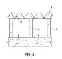
- FIG. 3 is a fragmentary cross-sectional view of a portion of the Wheeler bottom type underdrain.
- FIG. 4 is a plan view of one type of distribution member illustrated in FIG. 1 having a control orifice of 9/16 inches in diameter. This distribution member corresponds to the color green in the legend depicted in FIG. 2 .
- FIG. 5 is a plan view of one type of distribution member illustrated in FIG. 1 having a control orifice of 19/32 inches in diameter. This distribution member corresponds to the color purple in the legend depicted in FIG. 2 .
- FIG. 6 is a plan view of one type of distribution member illustrated in FIG. 1 having a control orifice of 5 ⁇ 8 inches in diameter. This distribution member corresponds to the color red in the legend depicted in FIG. 2 .
- FIG. 7 is a plan view of one type of distribution member illustrated in FIG. 1 having a control orifice of 41/64 inches in diameter. This distribution member corresponds to the color blue in the legend depicted in FIG. 2 .
- FIG. 8 is a plan view of one type of distribution member illustrated in FIG. 1 having a control orifice of 11/16 inches in diameter. This distribution member corresponds to the color yellow in the legend depicted in FIG. 2 .
- FIG. 9 is a fragmentary plan view of a portion of a Wheeler bottom type filter.
- FIG. 10 is cross-sectional view taken along lines 10 - 10 in FIG. 9 .
- FIG. 11 is a fragmentary cross-sectional of an alternative embodiment of the present invention.
- FIG. 12 is a fragmentary bottom view from the perspective of lines 12 - 12 in FIG. 11 .
- FIG. 13 is a fragmentary cross-sectional of another alternative embodiment of the present invention.
- FIG. 14 is a fragmentary bottom view from the perspective of lines 14 - 14 in FIG. 13 .
- FIG. 15 is a fragmentary cross-sectional of a further alternative embodiment of the present invention.
- FIG. 16 is a fragmentary bottom view from the perspective of lines 16 - 16 in FIG. 15 .
- FIG. 17 is a fragmentary cross-sectional view of yet a further alternative embodiment of the present invention.
- FIG. 18 is a fragmentary cross-sectional of yet still another alternative embodiment of the present invention.
- FIG. 19 is a plan view of a distribution formed in accordance with yet still a further embodiment of the present invention.
- FIG. 20 is an elevation view of the embodiment illustrated in FIG. 19 .
- FIG. 21 is a cross-sectional view of the embodiment illustrated in FIG. 19 where the cross-section is taken along lines 21 - 21 in FIG. 22 .
- FIG. 22 is a cross-sectional view of the embodiment illustrated in FIG. 19 where the cross-section is taken along lines 22 - 22 in FIG. 20 .
- plenum refers to a chamber below a filter bed where the chamber extends below substantially the entirety of the filter bed.
- chambers that extend below only a minor portion of the corresponding filter bed are not a “plenum” as that term is used herein.
- Cone shaped as used herein includes within its definition pyramidal shaped objects.
- This embodiment employs five different types of fluid distribution members 2 , 4 , 6 , 8 , and 10 .
- Each of the fluid distribution members 2 , 4 , 6 , 8 , and 10 have at least on hydraulic characteristic that differs from the other types of fluid distribution members.
- the at least one different hydraulic characteristic is the different sizes of the control orifices 12 , 14 , 16 , 18 , and 20 .
- Control orifice 12 has a diameter of 9/16 inches.
- Control orifice 14 has a diameter of 19/32 inches.
- Control orifice 16 has a diameter of 5 ⁇ 8 inches.
- Control orifice 18 has a diameter of 41/64 inches.
- Control orifice 20 has a diameter of 11/16 inches.
- this embodiment of the present invention is able to readily compensate for pressure differences across the plenum A formed below the Wheeler bottom underdrain B.
- a filter bed (not shown) is supported above the Wheeler bottom underdrain B by a plurality of piers C. Plenum A extends below substantially the entirety of the filter bed.
- the present invention is able to eliminate or substantially reduce maldistribution of a fluid passing from plenum A through fluid distribution members 2 , 4 , 6 , 8 , and 10 to the filter bed.
- this embodiment of the present invention is able to achieve a more thorough and hence more effective cleaning of the filter bed when a washing liquid (e.g., filtered or unfiltered water) and/or gas (e.g., gas) is distributed in a substantially uniform manner throughout all portions of the filter bed.
- This embodiment is also able to achieve a more effective filtering of influent as the influent will be distributed in a uniform manner throughout all portions of the filter bed.
- the diameter of the control orifice can be determined by substituting in the applicable values. For the highest pressure measured of 5.6 ft.,
- a control orifice with a diameter of 0.67 in. can be installed in the areas of highest pressure to equalize the flow rate with the flow rate through the control orifice having a diameter of 0.75 inches at the lowest pressure measured at 3.6 ft. The same method can be used to determine the required control orifice diameter for any pressure in the plenum.
- control orifices While five different sizes of control orifices are used in this embodiment, it will be readily appreciated that the number of different control orifices may be more or less depending upon the characteristics of the filter.
- Fluid distribution members or inserts 2 , 4 , 6 , 8 , and 10 are preferably formed from plastic and configured to be readily inserted from above underdrain B into the cone-shaped depressions 22 formed in a typical wheeler bottom underdrain B.
- the underdrain could be monolithic or precast.
- the underdrain B as shown herein is formed of concrete. However, it will be readily appreciated that any suitable material may be used.
- the present invention is not limited to being used with wheeler bottom underdrains. Rather, the present invention can be used with any suitable underdrain including but not limited to plenum type underdrains (e.g., e.g., Wheeler bottoms, nozzle bottoms, strainers, Hydrocones, etc.)
- the fluid distribution members 2 , 4 , 6 , 8 , and 10 are color coded inserts so that an individual can readily ascertain where a particular type of fluid distribution member is to go.
- yellow would identify a fluid distribution insert 10 whose control orifice 20 is 11/16 in.
- blue would identify a fluid distribution insert 8 whose control orifice 18 is 41/64 in.
- red would identify a fluid distribution insert 6 whose control orifice 16 is 5 ⁇ 8 in.
- the present invention is not limited to the color scheme disclosed herein. Rather, any suitable color scheme could be used. Further, the present invention is not limited to colors but could be any suitable identifying indicia including numbers, symbols, letters, etc. It will be appreciated that the aforementioned identifying indicia scheme is optional.
- FIGS. 11 to 14 two alternative embodiments are illustrated that utilize varying sizes of control orifices to compensate for pressure differences in plenum A to reduce or eliminate maldistribution of one or more fluids through a granular media filter bed.
- this embodiment utilizes a plurality of generally cylindrical inserts 24 that have a bore 26 extending therethrough to allow a fluid to pass through each of the inserts 24 .
- inserts 24 are preferably configured to be inserted in a conventional thimble 28 of a Wheeler bottom underdrain B.
- the diameters of the bores 26 may correspond to the orifices sizes of inserts 2 , 4 , 6 , 8 and 10 .
- the number inserts having different size bores as well as the particular sizes of the bores may be varied as desired.
- this embodiment utilizes a plurality of plates 30 that have a control orifice 32 formed therein.
- plates 32 are preferably disposed below a conventional thimble 28 of a wheeler bottom underdrain B.
- the diameters of the control orifices 32 may correspond to the orifices sizes of inserts 2 , 4 , 6 , 8 and 10 .
- the number plates having different size control orifices as well as the particular sizes of the control orifices may be varied as desired.
- FIGS. 15 to 18 three further alternative embodiments of the present invention are illustrated. As opposed to utilizing a control orifice to compensate for pressure differences in plenum A, these embodiments utilize differences in discharge coefficients to compensate for pressure differences across plenum A. However, it will be readily appreciated that both control orifice sizes and discharge coefficients may be used in the same embodiment to compensate for pressure variances across a plenum.
- this embodiment employs a plurality of plates 34 preferably disposed below the generally cone-shaped depressions 22 formed in underdrain B. As seen in FIGS. 15 and 16 , plate 34 has a tapered opening 36 . By varying the degree of tapering including no taper between the numerous plates 34 used in any given installation, the discharge coefficient can be readily varied among the numerous plates 34 to compensate for variances in pressure across plenum A.
- a plurality of tapered nozzles 38 are preferably disposed in the generally cone-shaped depressions 22 .
- the discharge coefficient can be readily varied among the nozzles 38 to compensate for variances in pressure across plenum A.
- a plurality of extension nozzles 40 are used to compensate for pressure variances in plenum A.
- the discharge coefficient can be readily varied among the numerous nozzles 40 across the underdrain B to compensate for variances in pressure across plenum A.
- the fluid distributor is a nozzle or strainer 42 .
- Nozzle 42 includes a strainer cap 44 and a strainer stem 46 .
- Stem 46 is configured to rotate relative to cap 44 .
- cap 44 includes an orientation mark 45 identifying the location of two oppositely disposed openings 48 and 50 formed in an inner annular wall portion 52 .
- Stem 46 includes an orientation mark 54 identifying the location of two oppositely disposed openings 56 and 58 formed in a hollow annular stem 46 . As seen in FIG.
Landscapes
- Chemical & Material Sciences (AREA)
- Chemical Kinetics & Catalysis (AREA)
- Filtration Of Liquid (AREA)
Abstract
Description
Q=19.636Cd√{square root over (h)}
Where Q=flow thru the orifice in gpm, C=the orifice discharge coefficient (dimensionless), d=the diameter of the orifice in inches and h=the headloss across the orifice in ft. water column This equation may be rearranged to solve for the orifice diameter d, as follows:
Knowing the desired flow rate through each of the orifices (in most cases it will be desired to have substantially the same flow rate through each of the control orifices of the
Therefore, a control orifice with a diameter of 0.67 in. can be installed in the areas of highest pressure to equalize the flow rate with the flow rate through the control orifice having a diameter of 0.75 inches at the lowest pressure measured at 3.6 ft. The same method can be used to determine the required control orifice diameter for any pressure in the plenum.
Claims (27)
Priority Applications (1)
| Application Number | Priority Date | Filing Date | Title |
|---|---|---|---|
| US12/929,416 US8668092B2 (en) | 2006-10-27 | 2011-01-21 | System and method for uniformly distributing a fluid through a filter bed in a filter |
Applications Claiming Priority (3)
| Application Number | Priority Date | Filing Date | Title |
|---|---|---|---|
| US11/588,210 US7736506B2 (en) | 2006-10-27 | 2006-10-27 | System and method for uniformly distributing a fluid through a filter bed in a filter |
| US11/606,012 US7922903B2 (en) | 2006-10-27 | 2006-11-30 | System and method for uniformly distributing a fluid through a filter bed in a filter |
| US12/929,416 US8668092B2 (en) | 2006-10-27 | 2011-01-21 | System and method for uniformly distributing a fluid through a filter bed in a filter |
Related Parent Applications (1)
| Application Number | Title | Priority Date | Filing Date |
|---|---|---|---|
| US11/606,012 Continuation-In-Part US7922903B2 (en) | 2006-10-27 | 2006-11-30 | System and method for uniformly distributing a fluid through a filter bed in a filter |
Publications (2)
| Publication Number | Publication Date |
|---|---|
| US20110226687A1 US20110226687A1 (en) | 2011-09-22 |
| US8668092B2 true US8668092B2 (en) | 2014-03-11 |
Family
ID=44646379
Family Applications (1)
| Application Number | Title | Priority Date | Filing Date |
|---|---|---|---|
| US12/929,416 Active 2027-09-30 US8668092B2 (en) | 2006-10-27 | 2011-01-21 | System and method for uniformly distributing a fluid through a filter bed in a filter |
Country Status (1)
| Country | Link |
|---|---|
| US (1) | US8668092B2 (en) |
Families Citing this family (3)
| Publication number | Priority date | Publication date | Assignee | Title |
|---|---|---|---|---|
| CN102805959A (en) * | 2012-08-28 | 2012-12-05 | 中国水电顾问集团中南勘测设计研究院 | Filter improved small-resistance water distribution and air distribution system |
| ES2521790B1 (en) | 2013-04-10 | 2015-09-09 | Empresa Municipal De Aguas Y Saneamiento De Murcia, S.A. | OPEN FILTRATION EQUIPMENT FOR WATER TREATMENT STATION |
| US12246271B2 (en) * | 2023-04-04 | 2025-03-11 | De Nora Water Technologies, LLC | Media retention plate for a block underdrain system |
Citations (3)
| Publication number | Priority date | Publication date | Assignee | Title |
|---|---|---|---|---|
| US3456804A (en) * | 1966-10-26 | 1969-07-22 | M C G Corp | Filter bottoms |
| US5019259A (en) * | 1989-06-15 | 1991-05-28 | Hambley John B | Filter underdrain apparatus with partitioned distributor conduits |
| US20030047502A1 (en) * | 2001-09-10 | 2003-03-13 | Roberts R. Lee | Underdrain system |
-
2011
- 2011-01-21 US US12/929,416 patent/US8668092B2/en active Active
Patent Citations (3)
| Publication number | Priority date | Publication date | Assignee | Title |
|---|---|---|---|---|
| US3456804A (en) * | 1966-10-26 | 1969-07-22 | M C G Corp | Filter bottoms |
| US5019259A (en) * | 1989-06-15 | 1991-05-28 | Hambley John B | Filter underdrain apparatus with partitioned distributor conduits |
| US20030047502A1 (en) * | 2001-09-10 | 2003-03-13 | Roberts R. Lee | Underdrain system |
Also Published As
| Publication number | Publication date |
|---|---|
| US20110226687A1 (en) | 2011-09-22 |
Similar Documents
| Publication | Publication Date | Title |
|---|---|---|
| US5269920A (en) | Cap system for underdrains in gravity filters | |
| US5149427A (en) | Cap for underdrains in gravity filters | |
| US5296138A (en) | Underdrain for liquid purification systems | |
| US5639384A (en) | Apparatus and method for improving gas backwash in lateral underdrains | |
| US4707257A (en) | Air/water distributor underdrain | |
| AU656003B2 (en) | Apparatus for uniformly distribution gas and/or liquid in an underdrain lateral system | |
| RU2349364C1 (en) | Fluid medium distributor | |
| US5232592A (en) | Cap for underdrains in gravity filters | |
| US6261453B1 (en) | Fluid treatment media support system | |
| US7326351B2 (en) | Filter underdrain system for backwash flow and method for measuring same | |
| US4118322A (en) | Filtering apparatus for liquids | |
| US4265767A (en) | Method and apparatus for purification of waste water | |
| US7288193B2 (en) | Apparatus for directing fluids through a filter system | |
| US8070946B2 (en) | Underdrain for a filter system for filtering water or wastewater and a method of washing the filter system | |
| US8668092B2 (en) | System and method for uniformly distributing a fluid through a filter bed in a filter | |
| US4191652A (en) | Apparatus for filter backwashing | |
| US5028322A (en) | Low profile underdrain strainer assembly with improved distribution/fastening means | |
| CA2401377C (en) | An improved underdrain system | |
| US4200536A (en) | Underdrain for filter tanks | |
| US5160613A (en) | Purification underdrain with compensating chamber and baffle isolating backwash gas from backwash water | |
| US7922903B2 (en) | System and method for uniformly distributing a fluid through a filter bed in a filter | |
| US5176827A (en) | Filter underdrain with means to increase gas flow during simultaneous gas/liquid backwashing | |
| US20080099411A1 (en) | System and method for uniformly distributing a fluid through a filter bed in a filter | |
| US7758750B2 (en) | Flume for a filter system including at least one filter having a filter bed that is periodically washed with liquid, gas or a combination thereof | |
| KR20050088764A (en) | Porous block support apparatus and method for underdrain system |
Legal Events
| Date | Code | Title | Description |
|---|---|---|---|
| AS | Assignment |
Owner name: ROBERT MARKETING DE, INC., DELAWARE Free format text: ASSIGNMENT OF ASSIGNORS INTEREST;ASSIGNORS:ROBERTS, R LEE;ADDISON, MARK KEVIN;REEL/FRAME:026450/0222 Effective date: 20110527 |
|
| STCF | Information on status: patent grant |
Free format text: PATENTED CASE |
|
| MAFP | Maintenance fee payment |
Free format text: PAYMENT OF MAINTENANCE FEE, 4TH YR, SMALL ENTITY (ORIGINAL EVENT CODE: M2551) Year of fee payment: 4 |
|
| MAFP | Maintenance fee payment |
Free format text: PAYMENT OF MAINTENANCE FEE, 8TH YR, SMALL ENTITY (ORIGINAL EVENT CODE: M2552); ENTITY STATUS OF PATENT OWNER: SMALL ENTITY Year of fee payment: 8 |
|
| MAFP | Maintenance fee payment |
Free format text: PAYMENT OF MAINTENANCE FEE, 12TH YR, SMALL ENTITY (ORIGINAL EVENT CODE: M2553); ENTITY STATUS OF PATENT OWNER: SMALL ENTITY Year of fee payment: 12 |