US8664936B2 - Electronic motor vehicle control system with current measuring circuit - Google Patents
Electronic motor vehicle control system with current measuring circuit Download PDFInfo
- Publication number
- US8664936B2 US8664936B2 US12/934,350 US93435009A US8664936B2 US 8664936 B2 US8664936 B2 US 8664936B2 US 93435009 A US93435009 A US 93435009A US 8664936 B2 US8664936 B2 US 8664936B2
- Authority
- US
- United States
- Prior art keywords
- circuit
- path
- signal
- measurement
- switch
- Prior art date
- Legal status (The legal status is an assumption and is not a legal conclusion. Google has not performed a legal analysis and makes no representation as to the accuracy of the status listed.)
- Expired - Fee Related, expires
Links
Images




Classifications
-
- B—PERFORMING OPERATIONS; TRANSPORTING
- B60—VEHICLES IN GENERAL
- B60T—VEHICLE BRAKE CONTROL SYSTEMS OR PARTS THEREOF; BRAKE CONTROL SYSTEMS OR PARTS THEREOF, IN GENERAL; ARRANGEMENT OF BRAKING ELEMENTS ON VEHICLES IN GENERAL; PORTABLE DEVICES FOR PREVENTING UNWANTED MOVEMENT OF VEHICLES; VEHICLE MODIFICATIONS TO FACILITATE COOLING OF BRAKES
- B60T8/00—Arrangements for adjusting wheel-braking force to meet varying vehicular or ground-surface conditions, e.g. limiting or varying distribution of braking force
- B60T8/32—Arrangements for adjusting wheel-braking force to meet varying vehicular or ground-surface conditions, e.g. limiting or varying distribution of braking force responsive to a speed condition, e.g. acceleration or deceleration
- B60T8/34—Arrangements for adjusting wheel-braking force to meet varying vehicular or ground-surface conditions, e.g. limiting or varying distribution of braking force responsive to a speed condition, e.g. acceleration or deceleration having a fluid pressure regulator responsive to a speed condition
- B60T8/36—Arrangements for adjusting wheel-braking force to meet varying vehicular or ground-surface conditions, e.g. limiting or varying distribution of braking force responsive to a speed condition, e.g. acceleration or deceleration having a fluid pressure regulator responsive to a speed condition including a pilot valve responding to an electromagnetic force
-
- H—ELECTRICITY
- H03—ELECTRONIC CIRCUITRY
- H03K—PULSE TECHNIQUE
- H03K5/00—Manipulating of pulses not covered by one of the other main groups of this subclass
- H03K5/01—Shaping pulses
- H03K5/08—Shaping pulses by limiting; by thresholding; by slicing, i.e. combined limiting and thresholding
- H03K5/082—Shaping pulses by limiting; by thresholding; by slicing, i.e. combined limiting and thresholding with an adaptive threshold
- H03K5/084—Shaping pulses by limiting; by thresholding; by slicing, i.e. combined limiting and thresholding with an adaptive threshold modified by switching, e.g. by a periodic signal or by a signal in synchronism with the transitions of the output signal
-
- G—PHYSICS
- G01—MEASURING; TESTING
- G01R—MEASURING ELECTRIC VARIABLES; MEASURING MAGNETIC VARIABLES
- G01R19/00—Arrangements for measuring currents or voltages or for indicating presence or sign thereof
- G01R19/0092—Measuring current only
-
- H—ELECTRICITY
- H03—ELECTRONIC CIRCUITRY
- H03M—CODING; DECODING; CODE CONVERSION IN GENERAL
- H03M3/00—Conversion of analogue values to or from differential modulation
- H03M3/30—Delta-sigma modulation
- H03M3/39—Structural details of delta-sigma modulators, e.g. incremental delta-sigma modulators
- H03M3/412—Structural details of delta-sigma modulators, e.g. incremental delta-sigma modulators characterised by the number of quantisers and their type and resolution
- H03M3/422—Structural details of delta-sigma modulators, e.g. incremental delta-sigma modulators characterised by the number of quantisers and their type and resolution having one quantiser only
- H03M3/43—Structural details of delta-sigma modulators, e.g. incremental delta-sigma modulators characterised by the number of quantisers and their type and resolution having one quantiser only the quantiser being a single bit one
-
- H—ELECTRICITY
- H03—ELECTRONIC CIRCUITRY
- H03M—CODING; DECODING; CODE CONVERSION IN GENERAL
- H03M3/00—Conversion of analogue values to or from differential modulation
- H03M3/30—Delta-sigma modulation
- H03M3/39—Structural details of delta-sigma modulators, e.g. incremental delta-sigma modulators
- H03M3/436—Structural details of delta-sigma modulators, e.g. incremental delta-sigma modulators characterised by the order of the loop filter, e.g. error feedback type
- H03M3/456—Structural details of delta-sigma modulators, e.g. incremental delta-sigma modulators characterised by the order of the loop filter, e.g. error feedback type the modulator having a first order loop filter in the feedforward path
Definitions
- the invention relates to an electronic motor vehicle control system, to a method for current measurement, and to the use of the electronic motor vehicle control system in motor vehicle brake systems.
- valve actuation circuits in electronic controllers for motor vehicle brake systems which use pulse width modulation (PWM) to control the load current flowing through an essentially inductive load.
- PWM pulse width modulation
- the actuation circuit has an electronic current measuring circuit with a switch-on path and a recirculation path, these two measurement paths respectively comprising a sigma/delta modulator.
- the analog/digital converter is preferably in the form of a sigma/delta modulator.
- the electronic current measuring circuit performs current measurement for the load current by oversampling the analog measurement signal for the load current, which involves the clock rate of the respective sigma/delta modulator being significantly higher than the frequency of the pulse width modulation.
- a sigma/delta modulator firstly has the advantage that a load current can be measured by oversampling an analog measurement signal for the load current, as a result of which a plurality of current values per PWM period are captured and hence formal errors can be reduced or avoided.
- sigma/delta modulators are relatively inexpensive because their resolution is dependent not only on the order but also primarily on the clock rate at which they are operated and hence low-order modulators can also be used. It is thus preferred to use at least one 1-bit sigma/delta modulator for current measurement which requires particularly few semiconductor elements, is therefore inexpensive and can nevertheless achieve a high resolution by means of the clock rate.
- the at least one electronic current measuring circuit may be in the form of an integrated circuit and may be integrated in the electronic motor vehicle control system, which is also in the form of an integrated circuit.
- both the switch-on path and the switch-off path contain the current measuring devices described above.
- the signal conservation circuit is expediently activated whenever the switched-on phase is changed over to the recirculation phase, wherein the current is held for a defined hold time or until the voltage across the at least one power driver, particularly the switch-on driver or recirculation driver, of the valve actuation circuit has settled in a defined manner or a defined threshold voltage has been exceeded or undershot.
- the output current is kept essentially unchanged and provided for further processing (current measurement).
- the at least one sigma/delta modulator may comprise, a control loop which has an integrator element, such as an integrator, a capacitor or another component or an electronic circuit with a corresponding electrical response, a comparator and a controllable, switchable current source.
- This switchable current source may be designed such that it can drive various discrete current values and can be switched between these various current values.
- This switchable current source may comprise a parallel circuit of current sources, the currents of which can be added in a defined manner and this process may be switchable.
- This method may be complemented in that the changeover between the PWM phases involves an input switch of the signal conservation circuit of the measurement path which is associated with the PWM phase just finished being opened, as a result of which the analog measurement signal for the load current in this PWM path is provided in unaltered form essentially for a defined hold time, wherein this defined hold time is followed by an output switch of this signal conservation circuit being opened, as a result of which the A/D converter is frozen, and hence the measurement signal or an electrical variable which is dependent thereon being stored directly or indirectly for the duration of the PWM phase just begun plus the hold time which follows this PWM phase.
- the load current is determined only during a portion of the switched-on and/or switched-off phase.
- This current measurement may take place only during the switched-on phase. Expediently, the current measurement is started at the beginning of each PWM period or in each suitable PWM period.
- the method according to the second embodiment can be applied in driver circuits in which only the actuation path comprises an active component, especially since the method according to the first embodiment admits current measurement in the recirculation phase only little—if at all.
- the absence of one or more active semiconductor elements in the recirculation path means that such an actuation circuit affords cost advantages.
- the hold phase which follows the current measurement phase in the second embodiment may begin at a duty cycle of the PWM which is in a range between approximately 5 and 80 percent.
- the hold time is obtained from the rise above a defined voltage threshold by the gate or base voltage of the respective power driver in the switch-on or recirculation path.
- the hold time comprises an additional settling time for the input circuit of the respective PWM path.
- the time of the hold phase is essentially equally long for the transitions from recirculation phase to switched-on phase and switched-on phase to recirculation phase or is alternatively of different length.
- the hold time for the first embodiment may be obtained in total from the time interval beginning with the changeover time for the PWM and ending with a drop below or rise above a defined voltage threshold on the respective line driver or one of the line drivers of the valve actuation circuit and a time interval which is defined by a defined settling time for the at least one measurement path.
- the hold time may be set essentially permanently by the timing behavior of the current measuring circuit and/or the valve actuation circuit in a defined manner, in line with the aspects explained above.
- the respective changeover between the PWM phases involves, directly at the beginning of a respective PWM phase, the input switch of the signal conservation circuit of the respective PWM path being closed and the output switch of this signal conservation circuit of the one PWM path respectively being closed essentially when the output switch of the signal conservation circuit of the other PWM path is opened.
- a switch of the analog/digital converter of this measurement path is likewise opened and hence a memory element of this analog/digital converter is isolated and particularly this analog/digital converter is deactivated, wherein this switch of this analog/digital converter is also closed again or becomes additionally actuatable again essentially at the same time as the output switch of the signal conservation circuit of this measurement path, as a result of which this analog/digital converter is reactivated.
- the temporary connection and disconnection of the analog/digital converter prevents undesirable signal elements of the digital measurement signal for the load current from being produced.
- the temporary isolation of the memory element of the analog/digital converter by means of its switch means that during an inactive phase of the respective measurement path a change in the information stored directly or indirectly in the memory element, which is in the form of an integrator for a sigma/delta modulator, and may be kept essentially unchanged.
- the digital measurement signals from the PWM paths are preferably transmitted to a common evaluation circuit or are taken into account by the latter essentially within the time interval in which the output switch of the signal conservation circuit of the respective PWM path is closed, wherein the output signal from this common evaluation circuit contains at least the information about the amplitude of the measured load current, particularly for a respective PWM period.
- the common evaluation circuit comprises a common averaging device, which is in the form of a counter, for example.
- the output switch can be dispensed with, since the sigma/delta converter runs permanently in parallel.
- the invention also relates to the use of the electronic motor vehicle control system in a motor vehicle brake system.
- the electronic motor vehicle control system according to aspects of the invention and the method according to the aspects of the invention are preferably used in electronic motor vehicle brake systems, in which electromagnetic hydraulic valves are actuated by means of pulse width modulation in valve actuation circuits, to set the hydraulic pressure in wheel brakes of the motor vehicle.
- electromagnetic hydraulic valves are actuated by means of pulse width modulation in valve actuation circuits, to set the hydraulic pressure in wheel brakes of the motor vehicle.
- actuation circuits to set the hydraulic pressure in wheel brakes of the motor vehicle.
- FIG. 1 shows an exemplary embodiment of a current profile for a circuit with lowside and recirculation drivers in a valve actuation circuit
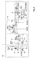
- FIG. 2 shows a switch-on path in an electronic current measuring circuit
- FIG. 3 shows a corresponding recirculation path for the current measuring circuit
- FIG. 4 shows signal profiles for a transition from recirculation phase to switched-on phase
- FIG. 5 shows signal profiles for a transition from switched-on phase to recirculation phase
- FIG. 6 shows signal profiles and current measurements with hold phases beginning during the switched-on phase
- FIG. 7 shows signal profiles and current measurements with a hold phase beginning during the actuation phase given a suitable duty cycle for the PWM.
- FIG. 1 shows an exemplary embodiment of a typical current profile through the lowside driver or through the recirculation driver of a valve actuation circuit, that is to say in line with the power driver of the switch-on and recirculation paths of a valve actuation circuit.
- this current essentially corresponds to the load current through the valve coil or is dependent thereon.
- the current profiles of I Recirc and I Lowside correspond to the currents to be measured in the recirculation phase and in the switched-on phase. At time t 0 , these two PWM phases are respectively changed over.
- the analog measurement current which is measured overall in continuous measurements is marked by the dotted or dash-dot profile over all the sections of the graph.
- the end of the transition phases is defined by virtue of the voltage across the respective line driver of the switch-on path or recirculation path of the valve actuation circuit being settled or a defined threshold voltage being undershot and additionally a defined settling time for the measurement path having passed. It has been found and is evident from FIG. 1 that the “measurement error” still made in line with the example within the transition phases is alternately positive and negative and the differential error therefore becomes very small if the duration of the transition phases is very much shorter than the period duration of the PWM. This practice thus advantageously also allows precise measurements to be performed when they are close in time to changeover operations between the two PWM phases.
- FIG. 2 shows an exemplary switch-on path 1 , as a measurement path in an electronic current measuring circuit, and also the switch-on path 2 a of a valve actuation circuit in line with the example.
- This switch-on path 2 a of the valve actuation circuit comprises inductive load or coil 21 for the valve, and a power driver 22 for the switch-on path.
- Supply potential REF 1 is firstly applied to coil 21 , and the potential VO is secondly applied to the node 23 between the coil 21 and the power driver 22 .
- the gate connection of the power driver 22 has the signal LS-DRIVE applied to it, said signal turning on the power driver 22 when the switch-on path is activated.
- the switch-on path 1 of the current measuring circuit comprises an input circuit 11 with a sense amplifier 112 and a sense FET 111 , a signal conservation circuit 12 with an input switch 121 , an output switch 122 and a capacitance 123 , and also a sigma/delta modulator 13 .
- power driver 22 with gate input LS-DRIVE and input switch 121 with switching signal VDRVEN are actuated simultaneously, particularly at the same time as the signal EnLsSync described further below.
- the signal conservation circuit 12 is supplied with the analog measurement signal for the load current by the input circuit 11 from the beginning of a switched-on phase to the end of said switched-on phase.
- a sigma/delta modulator 13 which in line with the example is in the form of a control loop, comprises a capacitor 131 as an integrator element or integrator.
- the capacitor 131 serves as a memory element which provides at least one information item about the analog measurement signal for the load current which was recently provided for the sigma/delta modulator 13 .
- the respective opening of the output switch 122 of the signal conservation circuit and the switch 132 of the sigma/delta modulator electrically isolates the memory element or capacitor 131 .
- the switch 132 simultaneously serves as a switch of a regulatable current source of the sigma/delta modulator 13 .
- the signal EnLsSync is used to prompt the switch 132 to open at the same time as the output switch 122 at the end of the hold time for a defined period.
- the signal conservation circuit 12 and the capacitor or memory element 131 respectively store the present, most recently provided state of the analog measurement signal for the load current.
- the signal conservation circuit 12 stores this last state of the analog measurement signal, in line with the example, until the beginning of the next switched-on phase, and the capacitor 131 stores it until the end of the defined hold phase, which follows the beginning of the next switched-on phase.
- the signal EnLsSync again prompts the output switch 122 to be closed and prompts the switch 132 to be enabled when the relevant output switch of the signal conservation circuit in the recirculation path is opened.
- the AND gate 133 the input side of which is connected to the switching signal EnLsSync and the output SENSE of the sigma/delta modulator 13 , is used to actuate the output side of the switch 132 .
- the switch 132 is open and cannot freely change over the current source of the sigma/delta modulator by means of the digital measurement signal for the load current SENSE, which means that the sigma/delta modulator 13 is deactivated. If the signal EnLsSync corresponds to a logic “1”, the output switch 122 is closed and the switch 132 is not constantly open, the switch 132 in this case being freely switchable or actuated on the basis of the digital measurement signal SENSE.
- the signal EnLsSync is in this case additionally applied to the “set” input of a D-type flip-flop 134 of the sigma/delta modulator 13 , as a result of which the sigma/delta modulator 13 can additionally be deactivated when the signal EnLsSync is at a logic “0”. Operation of the circuit is alternatively also possible without this signal line. In line with the example, the sigma/delta modulator 13 is operated at a much higher clock frequency clk than the frequency of the PWM.
- FIG. 3 shows the exemplary recirculation path 3 , as a measurement path in an electronic current measuring circuit, and the recirculation path 2 b of a valve actuation circuit based on the example.
- the recirculation path 2 b of the valve actuation circuit has coil 21 of the valve, the power driver of the recirculation path 24 , the gate side of which is actuated by the signal HS-DRIVE, node 23 at potential VO and an additional power driver 25 for rapid disconnection.
- the hold time is determined by considering the voltage across the power driver 24 or the drop in said voltage below a defined threshold voltage or the rise above a defined threshold voltage for HS-DRIVE.
- the hold time accordingly lasts from the switch-on time of the power driver 24 until the signals explained above drop below or rise above the threshold voltages explained above, with it additionally being necessary to wait a defined settling time for the measurement path.
- the recirculation path 3 of the current measuring circuit likewise comprises an input circuit 31 with a sense amplifier 312 and sense FET 311 , a signal conservation circuit 32 with an input switch 321 , an output switch 322 and a capacitance 323 , and a sigma/delta modulator 33 with a digital measurement signal for the load current REDUN as output signal.
- the input circuit 31 provides the analog measurement signal for the load current.
- the input switch 321 is actuated by the inverted signal VDRVEN and is therefore open and closed alternately with respect to input switch 121 from FIG. 2 .
- the analog measurement signal for the load current is provided in essentially unchanged form for the purpose of measurement by the sigma/delta modulator 33 .
- the output switch 322 and the switch 332 of the sigma/delta modulator 33 are opened when prompted by a logic “0” of the signal EnHsSync and are kept constantly open for a defined duration by means of the AND gate 333 , the input side of which has the signal EnHsSync and the digital output signal REDUN from the sigma/delta modulator 33 applied to it and the output side of which actuates the switch 332 .
- the signal EnHsSync can preferably be actuated at the same time as the signal VDRVEN.
- the switchable current source of the sigma/delta modulator 33 not being freely switchable or switch 332 being able to be closed and because the signal EnHsSync is additionally applied to the “set input” of a D-type flip-flop 334 of the sigma/delta modulator 33 , the sigma/delta modulator 33 is deactivated through a “0” of the signal EnHsSync and stops the current measurement until the signal EnHsSync corresponds to a logic “1” again in the next recirculation phase at the end of the hold phase of the switch-on path and the output switch 322 of the current measuring circuit is therefore closed again, the switch 332 is freely switchable again on the basis of the signal REDUN and there is a “1” again at the “set” input of the D-type flip-flop 334 .
- FIG. 4 shows exemplary signal profiles for the signals VDRVEN, V VO , that is to say the voltage amplitude of the potential VO with respect to ground, EnLsSync and also SENSE, the meaning of which is explained with reference to FIG. 2 , for a transition from the recirculation phase to the switched-on phase.
- the first measurement cycle of the sigma/delta modulator 13 after the beginning of the switched-on phase is illustrated by “First Sample” and occurs after closure of the output switch 122 , which is actuated by the signal EnLsSync.
- FIG. 5 shows an example of a transition from the switched-on phase to the recirculation phase using the signal profiles VDRVEN, V VO , EnHsSync and REDUN, which are explained with reference to FIG. 3 .
- the signal profile in FIG. 6 shows the load current 601 (I coil ) and two signal profiles 602 and 603 , ascertained in different ways and representing the measurement current, from a current measurement with a hold phase.
- the measurement graph comes from a circuit which comprises only an actuation FET and in which the load current recirculates via an external freewheeling diode.
- the hold phase 604 in which a current value is stored (flat portion of the curve), begins at a time which corresponds to approximately half of the switched-on phase (t on / 2 ).
- the hold phase of curve 602 begins only after the switched-on phase (t on ) has elapsed completely.
- both current measurement curves jump to the initial value of the actuation current applied at this time (in FIG. 6 , at approximately 0.89 A).
- the signal profile in FIG. 7 shows the load current 701 (I coil ) and a signal profile 703 representing the measurement current when the hold phase 704 , in which a current value is stored (flat portion of the curve), begins at a time which corresponds to approximately 28 percent of the duty cycle (time arrow 706 ). In line with FIG. 4 , it ends when the actuation phase ends (arrow 705 ). In order to eliminate the formal error completely, it would be inherently necessary to scan the entire current profile, including the actuation and recirculation phases, as completely as possible. In a simplified circuit with only one actuation driver without a recirculation driver (for example with one or more external freewheeling diodes, which are difficult to use for current measurement), this is not readily possible, however.
- the method of keeping the measurement constant from a duty cycle of approximately 28 percent over a portion of the remaining actuation phase and over the entire recirculation phase results in a surprisingly high level of accuracy for the current measurement even under different loads and constraints as a result of the similarly sized integral areas (plus symbol and minus symbol in FIG. 7 ), which are obtained from the difference between the RMS current and the measurement current, which essentially cancel one another out.
- the simplified multichannel circuit in this case preferably manages with just one external measurement resistor if the actuation transistor used is a sense FET.
Landscapes
- Physics & Mathematics (AREA)
- Engineering & Computer Science (AREA)
- Electromagnetism (AREA)
- Fluid Mechanics (AREA)
- Transportation (AREA)
- Mechanical Engineering (AREA)
- Nonlinear Science (AREA)
- Electronic Switches (AREA)
- Dc-Dc Converters (AREA)
- Compression, Expansion, Code Conversion, And Decoders (AREA)
- Inverter Devices (AREA)
Abstract
Description
wherein ti is the pulse duration and T is the period duration. It has been found that a range of between approximately 26 and 30 percent is most advantageous for the duty cycle. If the time of the beginning of the hold phase is stipulated as described above, the formal error defined below is astonishingly small even under changing constraints (different loads and ambient conditions).
Claims (24)
Applications Claiming Priority (4)
| Application Number | Priority Date | Filing Date | Title |
|---|---|---|---|
| DE102008015841.0 | 2008-03-27 | ||
| DE102008015841 | 2008-03-27 | ||
| DE102008015841A DE102008015841A1 (en) | 2008-03-27 | 2008-03-27 | Electronic motor vehicle control system with current measuring circuit |
| PCT/EP2009/053537 WO2009118351A1 (en) | 2008-03-27 | 2009-03-25 | Electronic motor vehicle control system with current measuring circuit |
Publications (2)
| Publication Number | Publication Date |
|---|---|
| US20110057644A1 US20110057644A1 (en) | 2011-03-10 |
| US8664936B2 true US8664936B2 (en) | 2014-03-04 |
Family
ID=40848427
Family Applications (1)
| Application Number | Title | Priority Date | Filing Date |
|---|---|---|---|
| US12/934,350 Expired - Fee Related US8664936B2 (en) | 2008-03-27 | 2009-03-25 | Electronic motor vehicle control system with current measuring circuit |
Country Status (5)
| Country | Link |
|---|---|
| US (1) | US8664936B2 (en) |
| EP (1) | EP2265478B1 (en) |
| CN (1) | CN101980905B (en) |
| DE (1) | DE102008015841A1 (en) |
| WO (1) | WO2009118351A1 (en) |
Cited By (1)
| Publication number | Priority date | Publication date | Assignee | Title |
|---|---|---|---|---|
| US9294063B1 (en) * | 2012-05-15 | 2016-03-22 | Maxim Integrated Products, Inc. | Digital input circuit and method for high voltage sensors |
Families Citing this family (9)
| Publication number | Priority date | Publication date | Assignee | Title |
|---|---|---|---|---|
| DE102012204122B4 (en) | 2011-05-03 | 2024-06-06 | Continental Automotive Technologies GmbH | Electronic PWM control circuit for controlling loads, in particular solenoid valves, PWM control methods and their use |
| DE102012223285A1 (en) | 2012-01-13 | 2013-07-18 | Continental Teves Ag & Co. Ohg | Electronic circuit arrangement structure for monitoring pulse width modulation (PWM) control electronics of control device for brake system of e.g. motor car, has logic circuit to process time of power driver and PWM period duration |
| WO2014060787A1 (en) * | 2012-10-15 | 2014-04-24 | Freescale Semiconductor, Inc. | An inductive load control circuit, a braking system for a vehicle and a method of measuring current in an inductive load control circuit |
| DE102013204877A1 (en) | 2013-03-20 | 2014-09-25 | Continental Teves Ag & Co. Ohg | Method and electronic circuit arrangement for controlling a load current in a motor vehicle control unit |
| DE102014208161A1 (en) * | 2014-02-05 | 2015-08-06 | Conti Temic Microelectronic Gmbh | Method and device for determining a current for current regulation of a valve |
| DE102016207690A1 (en) * | 2016-05-04 | 2017-11-09 | Robert Bosch Gmbh | Method for determining the phase currents of an electrical machine with a power converter |
| DE102018100518A1 (en) * | 2018-01-11 | 2019-07-11 | Iav Gmbh Ingenieurgesellschaft Auto Und Verkehr | Method and device for monitoring a power electronic module |
| FR3082503B1 (en) * | 2018-06-14 | 2020-09-04 | Safran Landing Systems | EMERGENCY BRAKING PROCESS OF AN AIRCRAFT |
| CN111061327A (en) * | 2019-12-12 | 2020-04-24 | 联合汽车电子有限公司 | Closed-loop control system and closed-loop control method of driving circuit |
Citations (5)
| Publication number | Priority date | Publication date | Assignee | Title |
|---|---|---|---|---|
| DE10018650A1 (en) | 1999-05-07 | 2000-12-21 | Walcher Mestechnik Gmbh | Evaluation circuit for sensor has stimulation voltage coupled in with measurement frequency corresp. to oscillator resonant frequency, sample-and-hold element samples oscillation signal |
| WO2004030211A2 (en) | 2002-09-19 | 2004-04-08 | Siemens Aktiengesellschaft | Circuit configuration for averaging |
| US20040078132A1 (en) * | 2001-01-23 | 2004-04-22 | Wolfgang Fey | Circuit arrangement and method for measuring current in vehicle braking systems |
| DE102007001458A1 (en) | 2006-01-10 | 2007-09-06 | Continental Teves Ag & Co. Ohg | Method and electronic controller with current measuring circuit for current measurement by means of sense FET and sigma-delta modulation |
| WO2007131947A1 (en) | 2006-05-17 | 2007-11-22 | Continental Teves Ag & Co. Ohg | Method and pulse-width-modulated current control circuit for driving inductive loads in motor vehicles |
Family Cites Families (5)
| Publication number | Priority date | Publication date | Assignee | Title |
|---|---|---|---|---|
| DE19524808A1 (en) * | 1995-07-07 | 1997-01-09 | Thomson Brandt Gmbh | Process, encoder and decoder for resynchronization to a faulty data stream |
| JPH09181605A (en) * | 1995-12-27 | 1997-07-11 | Sony Corp | Analog / digital conversion and digital / analog conversion device |
| JPH1079949A (en) * | 1996-09-04 | 1998-03-24 | Oki Electric Ind Co Ltd | Image encoder, image decoder and image transmission system |
| CN1898112A (en) * | 2003-12-17 | 2007-01-17 | 大陆-特韦斯贸易合伙股份公司及两合公司 | Electronic control units for motor vehicle braking systems |
| WO2006042859A1 (en) * | 2004-10-20 | 2006-04-27 | Continental Teves Ag & Co. Ohg | Method for calculating the control current of an electrically controllable hydraulic valve |
-
2008
- 2008-03-27 DE DE102008015841A patent/DE102008015841A1/en not_active Withdrawn
-
2009
- 2009-03-25 CN CN2009801110909A patent/CN101980905B/en not_active Expired - Fee Related
- 2009-03-25 US US12/934,350 patent/US8664936B2/en not_active Expired - Fee Related
- 2009-03-25 EP EP09726060A patent/EP2265478B1/en active Active
- 2009-03-25 WO PCT/EP2009/053537 patent/WO2009118351A1/en not_active Ceased
Patent Citations (8)
| Publication number | Priority date | Publication date | Assignee | Title |
|---|---|---|---|---|
| DE10018650A1 (en) | 1999-05-07 | 2000-12-21 | Walcher Mestechnik Gmbh | Evaluation circuit for sensor has stimulation voltage coupled in with measurement frequency corresp. to oscillator resonant frequency, sample-and-hold element samples oscillation signal |
| US20040078132A1 (en) * | 2001-01-23 | 2004-04-22 | Wolfgang Fey | Circuit arrangement and method for measuring current in vehicle braking systems |
| WO2004030211A2 (en) | 2002-09-19 | 2004-04-08 | Siemens Aktiengesellschaft | Circuit configuration for averaging |
| WO2004030211A3 (en) | 2002-09-19 | 2004-07-29 | Siemens Ag | Circuit configuration for averaging |
| US20060004898A1 (en) | 2002-09-19 | 2006-01-05 | Siemens Aktiengesellschaft | Circuit configuration for averaging |
| DE102007001458A1 (en) | 2006-01-10 | 2007-09-06 | Continental Teves Ag & Co. Ohg | Method and electronic controller with current measuring circuit for current measurement by means of sense FET and sigma-delta modulation |
| US20090299592A1 (en) | 2006-01-10 | 2009-12-03 | Continental Teves Ag & Co. Ohg | Method and Electronic Regulator With A Current Measuring Circuit For Measuring The Current by Sense-Fet and Sigma-Delta Modulation |
| WO2007131947A1 (en) | 2006-05-17 | 2007-11-22 | Continental Teves Ag & Co. Ohg | Method and pulse-width-modulated current control circuit for driving inductive loads in motor vehicles |
Non-Patent Citations (1)
| Title |
|---|
| Axel Mertens et al.: "Voltage and Current Sensing in Power Electronic Converters Using Sigma-Delta A/D Conversion", IEEE Transactions on Industry Application, IEEE Service Center, Piscataway, NJ , BD. 34, NR. 5, Oct. 1, 1998 XP011022452, ISSN: 0093-9994. |
Cited By (1)
| Publication number | Priority date | Publication date | Assignee | Title |
|---|---|---|---|---|
| US9294063B1 (en) * | 2012-05-15 | 2016-03-22 | Maxim Integrated Products, Inc. | Digital input circuit and method for high voltage sensors |
Also Published As
| Publication number | Publication date |
|---|---|
| EP2265478B1 (en) | 2012-09-26 |
| WO2009118351A1 (en) | 2009-10-01 |
| CN101980905A (en) | 2011-02-23 |
| US20110057644A1 (en) | 2011-03-10 |
| DE102008015841A1 (en) | 2009-10-01 |
| EP2265478A1 (en) | 2010-12-29 |
| CN101980905B (en) | 2013-09-04 |
Similar Documents
| Publication | Publication Date | Title |
|---|---|---|
| US20110057644A1 (en) | Electronic motor vehicle control system with current measuring circuit | |
| US8131439B2 (en) | Method and electronic regulator with a current measuring circuit for measuring the current by sense-FET and sigma-delta modulation | |
| US7773016B2 (en) | Switching converters controlled via sigma delta modulation | |
| US9673704B2 (en) | Inductive load control circuit, a braking system for a vehicle and a method of measuring current in an inductive load control circuit | |
| US7848126B2 (en) | Integrating current regulator and method for regulating current | |
| US20100060257A1 (en) | Current sensor for power conversion | |
| US6934140B1 (en) | Frequency-controlled load driver for an electromechanical system | |
| CN107769780B (en) | Analog-to-digital converter, method for operating the same, method for operating an electric machine, and circuit | |
| US10044267B1 (en) | Current emulation auto-calibration with peak-current servo | |
| US9588157B2 (en) | Integrated circuit, current sense circuit for a pulse width modulation driver and method therefor | |
| US11319912B2 (en) | Electromagnetic valve driver | |
| US12222377B2 (en) | Intelligent semiconductor switch with integrated current measurement function | |
| US6873201B2 (en) | Circuit arrangement and method for actuating a semiconductor switch connected in series with an inductive load | |
| KR101771802B1 (en) | Method and device for controlling a solenoid actuator | |
| EP4537447A1 (en) | Inductance detection for power converters | |
| US11652479B2 (en) | Method of controlling a half-bridge circuit | |
| US9077294B2 (en) | Measurement of the output current of an amplifier circuit | |
| US20100315091A1 (en) | Detecting a Short Circuit in an Inductive Load Current Path | |
| US7180279B2 (en) | Method for driving pulse-width-controlled inductive loads, and a drive circuit for this purpose | |
| US7148741B2 (en) | Current supply circuit and method for supplying current to a load | |
| JP6137969B2 (en) | Current detection circuit, current control device | |
| US20230155471A1 (en) | Methods and Systems for Current Sensing in Power Converters | |
| EP1657726A1 (en) | Control circuit and method for a proportional solenoid valve, particularly for use on motor vehicles | |
| US20260005684A1 (en) | Current synthesizer | |
| JP2019163961A (en) | Current detection circuit |
Legal Events
| Date | Code | Title | Description |
|---|---|---|---|
| AS | Assignment |
Owner name: CONTINENTAL TEVES AG & CO. OHG, GERMANY Free format text: ASSIGNMENT OF ASSIGNORS INTEREST;ASSIGNORS:OEHLER, PETER;MICHEL, FRANK;HEINZ, MICHA;AND OTHERS;REEL/FRAME:025044/0924 Effective date: 20100818 |
|
| FEPP | Fee payment procedure |
Free format text: PAYOR NUMBER ASSIGNED (ORIGINAL EVENT CODE: ASPN); ENTITY STATUS OF PATENT OWNER: LARGE ENTITY |
|
| STCF | Information on status: patent grant |
Free format text: PATENTED CASE |
|
| CC | Certificate of correction | ||
| MAFP | Maintenance fee payment |
Free format text: PAYMENT OF MAINTENANCE FEE, 4TH YEAR, LARGE ENTITY (ORIGINAL EVENT CODE: M1551) Year of fee payment: 4 |
|
| MAFP | Maintenance fee payment |
Free format text: PAYMENT OF MAINTENANCE FEE, 8TH YEAR, LARGE ENTITY (ORIGINAL EVENT CODE: M1552); ENTITY STATUS OF PATENT OWNER: LARGE ENTITY Year of fee payment: 8 |
|
| FEPP | Fee payment procedure |
Free format text: MAINTENANCE FEE REMINDER MAILED (ORIGINAL EVENT CODE: REM.); ENTITY STATUS OF PATENT OWNER: LARGE ENTITY |
|
| LAPS | Lapse for failure to pay maintenance fees |
Free format text: PATENT EXPIRED FOR FAILURE TO PAY MAINTENANCE FEES (ORIGINAL EVENT CODE: EXP.); ENTITY STATUS OF PATENT OWNER: LARGE ENTITY |
|
| STCH | Information on status: patent discontinuation |
Free format text: PATENT EXPIRED DUE TO NONPAYMENT OF MAINTENANCE FEES UNDER 37 CFR 1.362 |
|
| FP | Lapsed due to failure to pay maintenance fee |
Effective date: 20260304 |