US8660200B2 - Dual-pass joint channel estimation and data demodulation for OFDM systems - Google Patents
Dual-pass joint channel estimation and data demodulation for OFDM systems Download PDFInfo
- Publication number
- US8660200B2 US8660200B2 US12/228,732 US22873208A US8660200B2 US 8660200 B2 US8660200 B2 US 8660200B2 US 22873208 A US22873208 A US 22873208A US 8660200 B2 US8660200 B2 US 8660200B2
- Authority
- US
- United States
- Prior art keywords
- data
- subcarriers
- channel estimate
- channel
- pattern
- Prior art date
- Legal status (The legal status is an assumption and is not a legal conclusion. Google has not performed a legal analysis and makes no representation as to the accuracy of the status listed.)
- Expired - Fee Related, expires
Links
Images




Classifications
-
- H—ELECTRICITY
- H04—ELECTRIC COMMUNICATION TECHNIQUE
- H04L—TRANSMISSION OF DIGITAL INFORMATION, e.g. TELEGRAPHIC COMMUNICATION
- H04L5/00—Arrangements affording multiple use of the transmission path
- H04L5/0001—Arrangements for dividing the transmission path
- H04L5/0003—Two-dimensional division
- H04L5/0005—Time-frequency
- H04L5/0007—Time-frequency the frequencies being orthogonal, e.g. OFDM(A) or DMT
-
- H—ELECTRICITY
- H04—ELECTRIC COMMUNICATION TECHNIQUE
- H04L—TRANSMISSION OF DIGITAL INFORMATION, e.g. TELEGRAPHIC COMMUNICATION
- H04L25/00—Baseband systems
- H04L25/02—Details ; arrangements for supplying electrical power along data transmission lines
- H04L25/0202—Channel estimation
- H04L25/0204—Channel estimation of multiple channels
-
- H—ELECTRICITY
- H04—ELECTRIC COMMUNICATION TECHNIQUE
- H04L—TRANSMISSION OF DIGITAL INFORMATION, e.g. TELEGRAPHIC COMMUNICATION
- H04L25/00—Baseband systems
- H04L25/02—Details ; arrangements for supplying electrical power along data transmission lines
- H04L25/0202—Channel estimation
- H04L25/0224—Channel estimation using sounding signals
- H04L25/0228—Channel estimation using sounding signals with direct estimation from sounding signals
- H04L25/023—Channel estimation using sounding signals with direct estimation from sounding signals with extension to other symbols
- H04L25/0232—Channel estimation using sounding signals with direct estimation from sounding signals with extension to other symbols by interpolation between sounding signals
-
- H—ELECTRICITY
- H04—ELECTRIC COMMUNICATION TECHNIQUE
- H04L—TRANSMISSION OF DIGITAL INFORMATION, e.g. TELEGRAPHIC COMMUNICATION
- H04L25/00—Baseband systems
- H04L25/02—Details ; arrangements for supplying electrical power along data transmission lines
- H04L25/0202—Channel estimation
- H04L25/024—Channel estimation channel estimation algorithms
- H04L25/025—Channel estimation channel estimation algorithms using least-mean-square [LMS] method
-
- H—ELECTRICITY
- H04—ELECTRIC COMMUNICATION TECHNIQUE
- H04L—TRANSMISSION OF DIGITAL INFORMATION, e.g. TELEGRAPHIC COMMUNICATION
- H04L25/00—Baseband systems
- H04L25/02—Details ; arrangements for supplying electrical power along data transmission lines
- H04L25/03—Shaping networks in transmitter or receiver, e.g. adaptive shaping networks
- H04L25/03006—Arrangements for removing intersymbol interference
- H04L25/03012—Arrangements for removing intersymbol interference operating in the time domain
-
- H—ELECTRICITY
- H04—ELECTRIC COMMUNICATION TECHNIQUE
- H04L—TRANSMISSION OF DIGITAL INFORMATION, e.g. TELEGRAPHIC COMMUNICATION
- H04L5/00—Arrangements affording multiple use of the transmission path
- H04L5/003—Arrangements for allocating sub-channels of the transmission path
- H04L5/0048—Allocation of pilot signals, i.e. of signals known to the receiver
Definitions
- the present invention relates generally to digital communication systems and, more particularly, to methods and receiver architectures for channel estimation and data demodulation.
- Quadrature Amplitude Modulation QAM
- PSK Phase Shift Keying
- BPSK Binary PSK
- QPSK Quadrature PSK
- the reference phase and amplitude of the modulation constellation are required at the receiver to estimate the symbols sent by the transmitter.
- the phase and amplitude of the constellation show random variations due to variety of channel impairments such as fading, frequency response of the channel, frequency offset, timing offset, etc.
- coherent detection the reference phase and amplitude of the modulation constellation may be obtained from reference symbols that may be transmitted along with the data symbols.
- previously detected symbols may be used as reference symbols for detecting current symbols.
- coherent detection provides superior performance than non-coherent detection.
- the overhead in terms of the bandwidth and power allocated for transmitting reference symbols is justified by the improved performance.
- the process of estimating the phase and amplitude of the channel to demodulate the symbols received on the channel is referred to as channel estimation.
- equalization The process of compensating the effect of the random phase and amplitude variation by using the estimated channel conditions.
- Orthogonal frequency division multiplexing is a multi-carrier modulation scheme used in many digital communication systems.
- OFDM a large number of closely spaced orthogonal subcarriers are used to transmit data as shown in FIG. 1 .
- the data are divided into several parallel data streams, one for each subcarrier.
- Each subcarrier is modulated with a conventional modulation scheme such as QAM, PSK, BPSK, or QPSK, at a low symbol rate while maintaining total data rate similar to single carrier modulation schemes in the same channel bandwidth.
- the frequency spacing between two adjacent subcarriers is referred as subcarrier spacing and it is denoted by ⁇ f.
- the rate at which the individual subcarriers are modulated is referred as symbol rate.
- the collection of all the subcarriers is referred as an OFDM symbol.
- the OFDM symbol rate is the same as the data symbol rate on each individual subcarrier.
- the OFDM symbol duration is denoted by T u .
- the OFDM signal is typically generated in frequency domain and then converted in time domain.
- An OFDM signal over one symbol duration is referred as an OFDM symbol in both time domain and frequency domain. Additional details about OFDM may be found in “3G Evolution: HSPA and LTE for Mobile Broadband” by Dahlman, Parkvall, Sköld and Beming, published by Academic Press, 1st Edition ⁇ 2007, the entire disclosure of which is hereby expressly incorporated by reference herein.
- OFDM orthogonal frequency division multiple access
- ISI intersymbol interference
- An uncorrupted OFDM signal can be demodulated without any interference between subcarriers.
- T u 1/ ⁇ f.
- the orthogonality between the subcarriers may be lost.
- the reason for this loss of subcarrier orthogonality is that the OFDM symbol boundary for one path will overlap with the symbol boundary of a different path, as illustrated in FIG. 2 .
- Cyclic prefix insertion is typically used in OFDM to address the loss of orthogonality in time dispersive channels and to make an OFDM signal robust to time dispersion on the radio channel. As illustrated in FIG. 3 , cyclic prefix insertion is performed by copying the last portion of the OFDM symbol and inserting it at the beginning of the OFDM symbol.
- Cyclic prefix insertion is beneficial in the sense that it makes an OFDM signal robust to time dispersion as long as the span of the time dispersion does not exceed the length of the cyclic prefix.
- the drawback of cyclic prefix insertion is that only a fraction T u /(T u +T CP ) of the received signal power is actually utilized by the OFDM demodulator. Cyclic prefix insertion also reduces the OFDM symbol rate from 1/T u to 1/(T u +T CP ).
- the samples corresponding to cyclic prefix are discarded before FFT processing.
- the linear convolution of a time dispersive radio channel will appear as a circular convolution during the OFDM symbol interval T u .
- the combination of OFDM modulation (Inverse FFT (IFFT) processing), a time dispersive radio channel, and OFDM demodulation (FFT processing) can then be seen as a frequency domain channel as illustrated in FIG. 4 , where the frequency domain channel taps h 0 , . . . , h N-1 can be directly derived from the channel impulse response, where N is the number of subcarriers used in an OFDM symbol.
- IFFT Inverse FFT
- FFT processing OFDM demodulation
- the output r n,k of the k th subcarrier at the receiver in FIG. 4 is the transmitted modulation symbol x n,k scaled and phase rotated by the complex frequency domain channel tap h k and impaired by noise w k .
- the receiver should multiply r n,k with the complex conjugate of estimated channel, ⁇ k , as illustrated in FIG. 5 . This is often referred as a one tap frequency domain equalizer being applied to each received subcarrier.
- the receiver has to estimate the frequency domain channel taps h 0 , . . . , h N-1 .
- the frequency domain channel taps can be estimated by first estimating the channel impulse response and then converting it into frequency domain to estimate h 0 , . . . , h N-1 .
- frequency domain channel taps may be estimated directly by using known reference symbols, which are inserted by the transmitter at regular intervals within the OFDM time-frequency grid, as illustrated in FIG. 6 .
- the reference symbols are often referred as pilot symbols.
- the subcarrier on which the pilot symbol is transmitted is referred as pilot subcarrier.
- pilot subcarrier The terms pilot, pilot subcarrier, and pilot symbol are used interchangeably herein.
- the receiver can estimate the frequency domain channel around the location of the reference symbols.
- the reference symbols should have a sufficiently high density in both the time and the frequency dimensions to be able to provide estimates for the entire time-frequency grid in a variety of channel conditions including radio propagation channels subject to high frequency and/or time selectivity.
- Different algorithms may be used for the channel estimation, such as averaging, linear interpolation, Minimum Mean Square Error (MMSE) estimation, etc. Some of these algorithms may require knowledge of the channel statistics.
- MMSE channel estimation method There are several traditional methods for performing channel estimation.
- One of the commonly used methods is the MMSE channel estimation method.
- the known channel estimates from the surrounding pilot positions are used to obtain MMSE channel estimate for data subcarriers.
- the pilots may be used from past and present OFDM symbols. Pilots from future OFDM symbols may also be used if storage and delay are not issues in an application.
- FIG. 7 illustrates an example of the MMSE channel estimation that uses seven pilots that are closest to the data symbol for which the channel estimate is needed.
- a two-dimensional (2D) channel estimation is performed using a filter whose coefficients are computed according to MMSE criteria using the joint time and frequency correlation of the propagation channel.
- the coefficient that multiplies the pilot channel estimate at position (4, 5) is proportional to the channel correlation between the position of the pilot (4, 5) and the position of the data symbol (9, 7) whose channel estimate is desired.
- the filter coefficient that multiplies the pilot channel estimate at position (8, 8) is proportional to the channel correlation between the position of the pilot (8, 8) and the position of the data symbol (9, 7) whose channel estimate is desired.
- the above described MMSE channel estimation method uses pilots from different OFDM symbols and from different subcarriers in those OFDM symbols and therefore it is referred herein as 2D MMSE channel estimation.
- the 2D MMSE exploits the channel correlation that is typically present along both the time axis and the frequency axis.
- This type of MMSE estimation is often too complex and therefore lower complexity versions that provide performance close to that of a 2D MMSE estimation are developed in literature.
- Separable 2D MMSE estimation is one example of commonly used lower complexity channel estimation method. In this method, first the MMSE estimation is performed in one dimension based on the channel correlation in that dimension and then second MMSE is performed in another dimension which in turn exploits the correlation in that dimension.
- FIG. 8 illustrates an example of a separable 2D channel estimation procedure where 1D filtering is performed along time axis first and then the next 1D filtering is performed along frequency axis.
- the pilot symbols used in 1D filters along each axis is limited to the pilots available along the axis for which the filtering is being performed.
- FIG. 9 illustrates the pilots available for 1D filtering along the frequency axis.
- pilots and the overhead there is a tradeoff between the density of pilots and the overhead in terms of portion of the total bandwidth and portion of the total power used up by the reference symbols such as pilots or training symbols. Although greater density of pilots is desirable for improved channel estimation, it takes away portion of the total bandwidth and portion of the total power that could otherwise be used for payload data transmission.
- Mobile wireless communication systems operate under very dynamic propagation channel conditions.
- the propagation channel conditions between the transmitter and the receiver can vary rapidly because of the fast movement of the mobile terminals.
- a larger number of reference symbols are embedded in the transmitted signal to enable receivers to reliably estimate the rapidly varying channel conditions.
- the channel estimation methods in the receiver must be designed to take full advantage of the available reference symbols embedded in the transmitted signal.
- some communication systems transmit the reference symbols at the beginning of a connection and then switch to payload data transmission.
- the receiver uses the initial reference (training) symbols to estimate the channel and then use this estimated channel for equalizing data symbols received during payload data transmission mode.
- DFE Decision Directed Channel Estimation
- DFE uses the previously demodulated and/or decoded data symbols for estimating the channel for the present data symbol.
- each OFDM symbol includes a large number of subcarriers that are individually modulated.
- the subcarriers that carry payload data are referred herein as data subcarriers and the subcarriers that carry reference symbols are referred herein as pilot subcarriers.
- the modulation information for the pilot subcarriers may be known a priori.
- the demodulated data symbols from previous OFDM symbols may be used for estimating channel for the present symbol.
- the position and density of pilots in the time-frequency grid may vary depending on the application and the particular OFDM system under consideration. In a given OFDM system, the position of pilot subcarriers may vary, often in a periodic manner, as a function of the OFDM symbol.
- channel estimation is employed for each of these subcarriers.
- the channel estimate for one or more of the data subcarriers in the current OFDM symbol may be obtained through pilots in the current OFDM symbol or through previously received pilots and demodulated data symbols.
- the channel estimate for a given data subcarrier is used to equalize and demodulate the received symbol on the given data subcarrier.
- a channel estimation and data demodulation method for use in a communication system.
- the method comprises performing a first channel estimate for a subset of data subcarriers of a symbol received by a receiver in the communication system according to a first pattern; performing a second channel estimate for the subset of data subcarriers of the symbol according to a second pattern, the second pattern being different than the first pattern; obtaining a multi-pass channel estimate for each of the data subcarriers in the subset by combining the first and second channel estimates; equalizing the data subcarriers based on the multi-pass channel estimate thereof; and demodulating the equalized data subcarriers to obtain demodulated data.
- performing the first channel estimate comprises performing a channel estimate for any pilot subcarrier associated with the subset; and obtaining an initial channel estimate for a given one of the data subcarriers according to the first pattern and based on the channel estimate for any associated pilot subcarrier.
- the method may further comprise performing an initial equalization on a data symbol received on the given one of the data subcarriers.
- the method further comprises performing an initial demodulation of the equalized data symbol and updating the initial channel estimate for the given data subcarrier.
- performing the second channel estimate comprises obtaining an initial channel estimate for the given one of the data subcarriers according to the second pattern and based on the channel estimate for any associated pilot subcarrier.
- the initial channel estimates may be based on at least one of a channel estimate from a prior symbol, a demodulated data symbol from the prior symbol and a pilot subcarrier from the prior symbol.
- the first and second channel estimates are combined by averaging the estimates together.
- Averaging may be done with a weighted average of the first and second channel estimates.
- the subset comprises all of the data subcarriers of the symbol.
- the symbol is an OFDM symbol.
- the subset of data subcarriers is selected from the symbol by the receiver. In any of the examples and alternatives herein, the subset of data subcarriers may be selected to span more than one symbol. Furthermore, the symbol may not include any pilot subcarriers.
- the method further comprises performing a third channel estimate for the subset of data subcarriers of the symbol according to a third pattern.
- the third pattern is different than the first and second patterns.
- the multi-pass channel estimate for each of the data subcarriers in the subset is obtained by combining the first, second and third channel estimates.
- a recording medium is recorded with a computer program for execution by a processor to perform a channel estimation and data demodulation process in a communication system.
- the process comprises performing a first channel estimate for a subset of data subcarriers of a symbol in the communication system according to a first pattern; performing a second channel estimate for the subset of data subcarriers of the symbol according to a second pattern, the second pattern being different than the first pattern; obtaining a multi-pass channel estimate for each of the data subcarriers in the subset by combining the first and second channel estimates; equalizing the data subcarriers based on the multi-pass channel estimate thereof; and demodulating the equalized data subcarriers to obtain demodulated data.
- performing the first channel estimate comprises performing a channel estimate for any pilot subcarrier associated with the subset and obtaining an initial channel estimate for a given one of the data subcarriers according to the first pattern and based on the channel estimate for any associated pilot subcarrier.
- the process may further comprise performing an initial equalization on a data symbol received on the given one of the data subcarriers.
- the process may also comprise performing an initial demodulation of the equalized data symbol and updating the initial channel estimate for the given data subcarrier.
- a wireless communication device for use on a wireless communication network.
- the wireless communication device comprises a baseband subsystem and a radio subsystem.
- the baseband subsystem includes a processor for managing operations of the wireless communication device.
- the radio frequency subsystem is operatively connected to the baseband subsystem.
- the radio frequency subsystem includes at least one receive chain operable to receive symbols from at least one channel of the wireless communication network.
- the processor is operable to perform a first channel estimate for a subset of data subcarriers of one of the symbols according to a first pattern; perform a second channel estimate for the subset of data subcarriers of the symbol according to a second pattern, the second pattern being different than the first pattern; obtain a multi-pass channel estimate for each of the data subcarriers in the subset by combining the first and second channel estimates; equalize the data subcarriers based on the multi-pass channel estimate thereof; and demodulate the equalized data subcarriers to obtain demodulated data.
- the wireless communication network employs an OFDM modulation scheme and the symbols are OFDM symbols.
- the device is a mobile station.
- the device is a base station of the wireless communication network.
- the processor is further operable to perform the first channel estimate by performing a channel estimate for any pilot subcarrier associated with the subset and obtaining an initial channel estimate for a given one of the data subcarriers according to the first pattern and based on the channel estimate for any associated pilot subcarrier.
- the processor may be further operable to perform an initial equalization on a data symbol received on the given one of the data subcarriers.
- the processor is further operable to perform an initial demodulation of the equalized data symbol and update the initial channel estimate for the given data subcarrier.
- the processor is also operable to perform the second channel estimate by obtaining an initial channel estimate for the given one of the data subcarriers according to the second pattern and based on the channel estimate for any associated pilot subcarrier.
- FIG. 1 illustrates a conventional OFDM communication system.
- FIG. 2 illustrates the effect of time dispersion on the orthogonality of the subcarriers in an OFDM communication system.
- FIG. 3 illustrates how cyclic prefix can help maintain the orthogonality of the subcarriers in an OFDM communication system.
- FIG. 4 illustrates a time domain and frequency domain model of an OFDM communication system.
- FIG. 5 illustrates the frequency domain model of an OFDM communication system and the equalization at the receiver.
- FIG. 7 illustrates 2D channel estimation in a time-frequency grid of an OFDM communication system.
- FIG. 9 illustrates 1D filtering for channel estimation along frequency axis for an OFDM communication system.
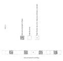
- FIG. 10 illustrates an OFDM symbol in frequency domain consisting of a number of data subcarriers and pilot subcarriers that may be organized in subsets of subcarriers.
- FIG. 11 illustrates a subset of subcarriers with eight data subcarriers and one pilot subcarrier considered in a first example in accordance with aspects of the present invention.
- FIG. 12 illustrates a first exemplary pattern for channel estimation with regard to FIG. 11 according to an aspect of the present invention.
- FIG. 13 illustrates a second exemplary pattern for channel estimation with regard to FIG. 11 according to an aspect of the present invention.
- FIG. 14 illustrates a subset of subcarriers with 12 data subcarriers and two pilot subcarriers considered in another example in accordance with aspects of the present invention.
- FIG. 15 illustrates a first exemplary pattern for channel estimation with regard to FIG. 14 according to an aspect of the present invention.
- FIG. 18 illustrates a first exemplary pattern 1 for channel estimation with regard to FIG. 17 according to an aspect of the present invention.
- FIG. 19 illustrates another exemplary pattern for channel estimation with regard to FIG. 17 according to an aspect of the present invention.
- FIG. 21 illustrates a diagram of a wireless mobile station for use with aspects of the present invention.
- FIG. 22 illustrates a baseband subsystem for use with aspects of the present invention.
- the demodulated data symbols from a current OFDM symbol may also be used as reference symbols and incorporated into the channel estimation process for the remaining data subcarriers in the current OFDM symbol.
- the demodulated data symbols from current OFDM symbol may be used in addition to any pilots from past and/or current and/or future OFDM symbols and demodulated data symbols from past OFDM symbols.
- the demodulated data symbols become available as additional reference symbols for estimating the channel for the remaining data subcarriers in the current OFDM symbol.
- All the reference symbols e.g., demodulated data symbols from past OFDM symbols, pilots from past and/or current and/or future OFDM symbols, and demodulated data symbols from current OFDM symbol, may be used in conjunction with each other to produce the channel estimate for the remaining data subcarriers in the current OFDM symbol.
- a channel estimate for a data subcarrier may be obtained by first obtaining two different channel estimates using different set of pilot and demodulated data symbols and then combining the two different channel estimates for the data subcarrier to obtain a new estimate that may have reduced channel estimation error.
- the two different channel estimates for a given data subcarrier may be obtained by employing either the method described in the '791 application or some other method that uses available reference symbols, including pilot and demodulated data symbols, from the current OFDM symbol in two different patterns as described herein.
- the demodulated data symbol is treated as a reference symbol like a pilot and in turn is used to refine the estimated channel of the same data subcarrier.
- the number of available channel estimates for each new data subcarrier within the same OFDM symbol grows after demodulating the data symbol received in each data subcarrier.
- the channel estimation and data demodulation work in a joint adaptive manner.
- the pattern in which the data subcarriers are demodulated affects channel estimates of the remaining data subcarriers.
- first joint channel estimation and demodulation may be performed for data subcarriers in a first pattern.
- h p1,i denote the channel estimate for data subcarrier i when the joint channel estimation and demodulation is performed according to the first pattern.
- joint channel estimation and demodulation may be performed in a second pattern.
- h p2,i denote the channel estimate for data subcarrier i when the joint channel estimation and demodulation is performed according to the second pattern.
- the dual-pass channel estimate for each data subcarrier is obtained by combining the two channel estimates obtained according to the two patterns.
- Two possible methods are as follows:
- h i h p ⁇ ⁇ 1 , i + h p ⁇ ⁇ 2 , i 2
- h i ⁇ ⁇ h p ⁇ ⁇ 1. ⁇ i + ( 1 - ⁇ ) ⁇ h p ⁇ ⁇ 2 , i 2
- ⁇ is a weighing factor which may be based on the relative magnitudes of the two channel estimates.
- the effect of noise and channel estimation errors may be different for the joint channel estimation and demodulation when performed according to different patterns for the same data subcarrier.
- the estimation errors may be random but the true channel conditions are the same regardless of whether the channel estimation is performed according to the first pattern or the second pattern.
- the dual-pass channel estimate for a data subcarrier is obtained by combining the two channel estimates obtained using the joint channel estimation and demodulation method according to two different patterns.
- the dual-pass channel estimate may have the reduced channel estimation error.
- the subset of subcarriers may be chosen such that it spans more than one OFDM symbol.
- the number of subcarriers in a subset is chosen to be 9 with 1 pilot subcarrier and 8 data subcarriers.
- the subcarriers are labeled as sc 1 through sc 9 as shown in FIG. 11 .
- sc 5 is the pilot subcarrier and the rest are data subcarriers.
- the channel estimation of the pilot subcarrier sc 5 is performed and it is labeled as h 5 (see FIG. 12 ).
- the channel estimation for the pilot subcarrier may be performed using known techniques such as the Least Squares channel estimation method.
- the channel estimate may not depend on the pattern since the modulation information for the pilot subcarrier is known a priori.
- the demodulated data symbol ⁇ circumflex over (x) ⁇ 4 may be used as a reference symbol to update the channel estimate for the data subcarrier sc 4 and the updated channel estimate is labeled as h p1,4 .
- the channel estimates h 5 and h p1,4 may be used to perform the channel estimation for the data subcarrier sc 6 next.
- the initial channel estimate for sc 6 is labeled as h′ p1,6 .
- the channel estimate h′ p1,6 may be used to perform equalization and demodulation of the received symbol r 6 on subcarrier sc 6 .
- the demodulated data symbol ⁇ circumflex over (x) ⁇ 6 may be used as a reference symbol to update the channel estimate for the data subcarrier sc 6 and the updated channel estimate is labeled as h p1,6 .
- This process may be continued for all the remaining data subcarriers in the subset as shown in table contained in FIG. 12 .
- the updated channel estimate of that subcarrier may be added to the set of available channel estimates as a basis for performing initial channel estimate for the next data subcarrier according to the first pattern.
- the channel estimate h 5 may be used to perform the channel estimation for the data subcarrier sc 6 next.
- the channel estimation may be performed using known techniques as described herein.
- the initial channel estimate for the data subcarrier sc 6 is labeled as h′ p2,6 (see FIG. 13 ).
- the channel estimate h′ p2,6 may be used to perform equalization and demodulation of the received symbol r 6 on data subcarrier sc 6 .
- the demodulated data symbol ⁇ circumflex over (x) ⁇ 6 may be used as a reference symbol to update the channel estimate for sc 6 and the updated channel estimate is labeled as h p2,6 .
- the channel estimates h 5 and h p2,6 may be used to perform the channel estimation for the data subcarrier sc 4 next.
- the initial channel estimate for sc 4 is labeled as h′ p2,4 .
- the channel estimate h′ p2,4 may be used to perform equalization and demodulation of the received symbol r 4 on data subcarrier sc 4 .
- the demodulated data symbol ⁇ circumflex over (x) ⁇ 4 may be used as a reference symbol to update the channel estimate for sc 4 and the updated channel estimate is labeled as h p2,4 .
- This process may be continued for all the remaining data subcarriers in the subset as shown in table contained in FIG. 13 .
- the updated channel estimate of that subcarrier may be added to the set of available channel estimates as a basis for performing initial channel estimate for the next data subcarrier according to the second pattern.
- the dual-pass channel estimate for each data subcarrier may be obtained by combining the two channel estimates obtained from the two patterns as follows:
- h i h p ⁇ ⁇ 1 , i + h p ⁇ ⁇ 2 , i 2
- This dual-pass channel estimate may then be used to perform final equalization and demodulation for data subcarriers.
- the number of subcarriers in a subset is chosen to be 14 with 2 pilot subcarriers and 12 data subcarriers.
- the subcarriers are labeled as sc 1 through sc 14 as shown in FIG. 14 .
- sc 5 and sc 9 are pilot subcarriers and the rest are data subcarriers.
- pilot subcarriers sc 5 and sc 9 may be performed and they are labeled as h 5 and h 9 respectively (see FIG. 15 ).
- the channel estimation for pilot subcarriers may be performed using known techniques such as the Least Squares channel estimation.
- pilot subcarriers the channel estimates may not depend on the pattern since the modulation information for the pilot subcarriers is known a priori.
- the channel estimates h 5 and h 9 may be used to perform channel estimation for the data subcarrier sc 8 next.
- the channel estimation may be performed using known techniques as described herein.
- the initial channel estimate for data subcarrier sc 8 is labeled as h′ p1,8 .
- the channel estimate h′ p1,8 may be used to perform equalization and demodulation of the received symbol r 8 on data subcarrier sc 8 .
- the demodulated data symbol ⁇ circumflex over (x) ⁇ 8 may be used as a reference symbol to update the channel estimate for data subcarrier sc 8 and the updated channel estimate is labeled as h p1,8 .
- the channel estimates h 5 , h 9 and h p1,8 may be used to perform channel estimation for the data subcarrier sc 6 next.
- the initial channel estimate for data subcarrier sc 6 is labeled as h′ p1,6 .
- the channel estimate h′ p1,6 may be used to perform equalization and demodulation of the received symbol r 6 on data subcarrier sc 6 .
- the demodulated data symbol ⁇ circumflex over (x) ⁇ 6 may be used as a reference symbol to update the channel estimate for the data subcarrier sc 6 and the updated channel estimate is labeled as h p1,6 .
- This process may be continued for all the remaining data subcarriers in the subset as shown in table contained in FIG. 15 .
- the updated channel estimate of that subcarrier may be added to the set of available channel estimates as a basis for performing initial channel estimate for the next data subcarrier according to the first pattern.
- the channel estimates h 5 and h 9 may be used to perform channel estimation for the data subcarrier sc 6 next.
- the channel estimation may be performed using techniques known in the literature as described in the background section.
- the initial channel estimate for sc 6 is labeled as h′ p2,6 (see FIG. 16 ).
- the channel estimate h′ p2,6 may be used to perform equalization and demodulation of the received symbol r 6 on data subcarrier sc 6 .
- the demodulated data symbol ⁇ circumflex over (x) ⁇ 6 may be used as a reference symbol to update the channel estimate for sc 6 and the updated channel estimate is labeled as h p2,6 .
- the channel estimates h 5 , h 9 and h p2,6 may be used to perform channel estimation for the data subcarrier sc 8 next.
- the initial channel estimate for data subcarrier sc 8 is labeled h′ p2,8 .
- the channel estimate h′ p2,8 is used to perform equalization and demodulation of the received symbol r 8 on data subcarrier sc 8 .
- the demodulated data symbol ⁇ circumflex over (x) ⁇ 8 may be used as a reference symbol to update the channel estimate for data subcarrier sc 8 and the new channel estimate is labeled as h p2,8 .
- This process may be continued for all the remaining data subcarriers in the subset as shown in table contained in FIG. 16 .
- the updated channel estimate of that subcarrier may be added to the set of available channel estimates as a basis for performing initial channel estimate for the next data subcarrier according to the second pattern.
- the dual-pass channel estimate for each data subcarrier may be obtained by combining the two channel estimates obtained from the first and second patterns as follows:
- h i h p ⁇ ⁇ 1 , i + h p ⁇ ⁇ 2 , i 2
- This dual-pass channel estimate may then be used to perform final equalization and demodulation for data subcarriers.
- the subset contains 28 subcarriers, 14 in one ODFM symbol and the other 14 from the adjacent OFDM symbol as shown in FIG. 17 .
- the subset contains 4 pilot subcarriers, 2 pilot subcarriers from each OFDM symbol and 24 data subcarriers, 12 data subcarriers from each OFDM symbol.
- the subcarriers are labeled as sc 1 through sc 28 as shown in FIG. 17 .
- sc 5 , sc 9 , sc 15 , and sc 27 are pilot subcarriers and the rest are data subcarriers.
- the channel estimation of pilot subcarriers may be performed and then the joint channel estimation and demodulation method may be applied according to the first and second patterns as shown in FIG. 18 and FIG. 19 , respectively.
- the dual-pass channel estimate for each data subcarrier may be obtained by combining the two channel estimates obtained from the two patterns as follows:
- h i h p ⁇ ⁇ 1 , i + h p ⁇ ⁇ 2 , i 2
- This dual-pass channel estimate may then be used to perform final equalization and demodulation for data subcarriers.
- the patterns are chosen such that the data subcarriers that are closer to the pilot subcarrier(s) may be considered earlier in the joint channel estimation and demodulation process. This is because the channel estimates of the pilot subcarriers are more reliable and more correlated to the channel estimates of the data subcarriers that are adjacent to the pilot subcarriers.
- the patterns may be chosen such that the channel estimation error of the dual-pass channel estimate is minimum.
- FIGS. 20A-C A dual-pass joint channel estimation and demodulation method in accordance with aspects of the present invention is discussed with regard to FIGS. 20A-C .
- a channel estimate such as a least squares channel estimate may be performed for the pilot subcarrier(s) of a current subset of subcarriers in one or more data symbols such as OFDM data symbols.
- the subset may contain some or all of the subcarriers in the data symbol.
- an initial channel estimate for a next data subcarrier in the current subset is obtained according to a first pattern.
- the first pattern preferably includes a first predetermined ordering of data subcarriers.
- the initial channel estimate for the next data subcarrier is desirably based upon available channel estimates for some or all of the pilot subcarrier(s) and other data subcarrier(s) which have already been estimated. For instance, referring to FIG. 12 , the initial channel estimate (h′ p1,4 ) for data subcarrier 4 (sc 4 ) is based solely on the available channel estimate (h 5 ) for the pilot subcarrier 5 (sc 5 ).
- the data symbol received on a selected data subcarrier may be equalized using the channel estimate from step S 102 .
- h′ p1,4 may be used to perform equalization on received data symbol r 4 on data subcarrier sc 4 .
- the equalized data symbol from the selected data subcarrier may be demodulated. For instance, in the above example, the resultant demodulated data symbol is ⁇ circumflex over (x) ⁇ 4 .
- the channel estimate for the selected data subcarrier is updated using the demodulated data symbol of step S 106 .
- the updated channel estimate of the selected data subcarrier is added to a list of available channel estimates for obtaining the channel estimate for a next data subcarrier in the subset of subcarriers of the data symbol. This may be seen in the second column from the left in the table of FIG. 12 .
- step S 112 a decision is made as to whether all data subcarriers in the subset have been processed according to the first pattern. If they have not, the process returns to step S 102 . If they have, then the process continues at step S 114 as shown in FIG. 20B .
- step S 114 an initial channel estimate for a next data subcarrier in the current subset is obtained according to a second pattern.
- the second pattern preferably includes a second predetermined ordering of data subcarriers different from the first predetermined ordering of data subcarriers.
- the initial channel estimate for the next data subcarrier is desirably based upon available channel estimates for some or all of the pilot subcarrier(s) and other data subcarrier(s) which have already been estimated in accordance with the second predetermined ordering. For instance, referring to FIG. 13 , the initial channel estimate (h′ p2,6 ) for data subcarrier 6 (sc 6 ) is based solely on the available channel estimate (h 5 ) for the pilot subcarrier 5 (sc 5 ).
- the data symbol received on a selected data subcarrier may be equalized using the channel estimate from step S 114 .
- h′ p2,6 may be used to perform equalization on received data symbol r 6 on data subcarrier sc 6 .
- the equalized data symbol from the selected data subcarrier may be demodulated. For instance, in the above example, the resultant demodulated data symbol is ⁇ circumflex over (x) ⁇ 6 .
- the channel estimate for the selected data subcarrier is updated using the demodulated data symbol of step S 118 .
- the updated channel estimate of the selected data subcarrier according to the second pattern is added to a list of available channel estimates for obtaining the channel estimate for a next data subcarrier in the subset of subcarriers of the data symbol. This may be seen in the second column from the left in the table of FIG. 13 .
- step S 124 a decision is made as to whether all data subcarriers in the subset have been processed according to the second pattern. If they have not, the process returns to step S 114 . If they have, then the process continues at step S 126 as shown in FIG. 20C .
- a dual-pass channel estimate for a next data subcarrier in the subset is obtained by combining the two channel estimates for that data subcarrier, which were obtained according to the first and second patterns. This may be done, as discussed above, using a straight average of the two channel estimates. Alternatively, a weighted average of the two channel estimates may be used. Other combinations of the two channel estimates are also possible.
- the dual-pass channel estimate may be used to equalize the data symbol received on the selected data subcarrier as shown in step S 128 and the equalized data symbol may be demodulated as shown in step S 130 .
- a decision is made at step S 132 as to whether all data subcarriers have been processed. If they have not, the process returns to step S 126 . If the subcarriers have all been processed, the process may terminate at step S 134 .
- aspects of the invention as described herein may be applied to a subset of subcarriers in a symbol such as an OFDM symbol or may be applied to all the subcarriers in the symbol.
- the dual-pass joint channel estimation and demodulation method may be applied to (OFDM) symbols that may or may not include pilot subcarriers.
- the initial channel estimates for the dual-pass joint channel estimation and demodulation method may use one or the combination of any the following:
- the invention described herein may be used for a subset of subcarriers composed of different number of subcarriers and different pilot subcarrier arrangements within the subset.
- two patterns have been considered for a dual-pass joint channel estimation and demodulation method.
- the invention is not limited to two patterns and may be extended to three or more patterns by appropriate modifications to the methods described herein.
- the dual-pass joint channel estimation and demodulation methods in accordance with the present invention have the following benefits. More accurate channel estimation for OFDM systems and thus improved data demodulation and increased throughput of the system. Improved demodulation leads to reduced error rate which in turn reduces retransmissions. This leads to improved bandwidth efficiency for the communication system and reduced power consumption for the receiver. The reduction in power consumption is a significant advantage for battery operated client terminals. Furthermore, the number of pilot subcarriers in an OFDM system may be reduced while maintaining the required performance. This improves the bandwidth efficiency of the communication system.
- MS 200 may include a baseband subsystem 202 and a radio frequency (“RF”) subsystem 204 .
- RF radio frequency
- a display/user interface 206 provides information to and receives input from the user.
- the user interface may include one or more actuators, a speaker and a microphone.
- the baseband subsystem 202 may include a controller 208 such as a microcontroller or other processor.
- the controller 208 desirably handles overall operation of the MS 200 , including management of the RF subsystem 204 . This may be done by software or firmware running on the controller 208 .
- Such software/firmware may embody any methods in accordance with aspects of the present invention.
- a signal processor 210 may be used to process samples from the RF subsystem 204 or other information sent or received by the MS 200 .
- the signal processor 210 may be a stand-alone component or may be part of the controller 208 .
- Memory 212 may be shared by or reserved solely for one or both of the controller 208 and the signal processor 210 .
- signal processing algorithms may be stored in a non-volatile section of memory 212 while coefficients and other data parameters may be stored in RAM.
- Peripherals 214 such as a full or partial keyboard, video or still image display, audio interface, etc may be employed and managed through the controller 208 .
- the RF subsystem 204 preferably provides two-way communication operation. It may include one or more receivers/receive chains, a transmitter, a synthesizer, a power amplifier, and one or more antennas operatively coupled together to enable OFDM or similar communication.
- the receive chain(s) is operable to receive signals from one or more channels in a wireless communication network.
- aspects of the present invention may be implemented in firmware of the signal processor 210 and/or the controller 208 of the baseband subsystem. In another alternative, aspects of the present invention may also be implemented as a combination of firmware and hardware of the baseband subsystem.
- aspects of the present invention may be implemented in network elements in addition to or distinct from implementation in mobile stations.
- one or more base stations of a wireless communication network such as an OFDM-based wireless network, may employ a baseband subsystem and/or an RF subsystem such as those detailed above.
- Software and/or firmware embodying any of the methods in accordance with aspects of the present invention may be executed by a controller or signal processor of the baseband subsystem or the RF subsystem.
- aspects of the present invention may also be implemented as a combination of firmware and hardware of the baseband subsystem.
- the dual-pass adaptive channel estimation may be applied to various communication systems such as systems based on an IEEE 802.16 wireless communication standard, an IEEE 802.11 wireless communication standard, an IEEE 802.20 wireless communication standard, a T-DMB wireless communication standard, a DVB-T wireless communication standard, a DVB-H wireless communication standard, a MediaFLO wireless communication standard, a Long Term Evolution of 3G-type wireless communication standard, cable modem standard, DSL standard, etc.
Landscapes
- Engineering & Computer Science (AREA)
- Signal Processing (AREA)
- Computer Networks & Wireless Communication (AREA)
- Power Engineering (AREA)
- Mobile Radio Communication Systems (AREA)
Abstract
Description
-
-
Set —1={(4, 5) (4, 9), (8, 4), (8, 8), (8, 12), (12, 7), (12, 11)}
-
-
- Average of the two channel estimates
-
- Weighted average of the two channel estimates
where α is a weighing factor which may be based on the relative magnitudes of the two channel estimates.
-
- Channel estimates from previous OFDM symbols
- Demodulated data symbols from previous OFDM symbols as reference symbols
- Pilot subcarriers from current and/or previous OFDM symbols
Claims (25)
Priority Applications (1)
| Application Number | Priority Date | Filing Date | Title |
|---|---|---|---|
| US12/228,732 US8660200B2 (en) | 2007-08-15 | 2008-08-15 | Dual-pass joint channel estimation and data demodulation for OFDM systems |
Applications Claiming Priority (2)
| Application Number | Priority Date | Filing Date | Title |
|---|---|---|---|
| US96470907P | 2007-08-15 | 2007-08-15 | |
| US12/228,732 US8660200B2 (en) | 2007-08-15 | 2008-08-15 | Dual-pass joint channel estimation and data demodulation for OFDM systems |
Publications (2)
| Publication Number | Publication Date |
|---|---|
| US20100040156A1 US20100040156A1 (en) | 2010-02-18 |
| US8660200B2 true US8660200B2 (en) | 2014-02-25 |
Family
ID=41681262
Family Applications (1)
| Application Number | Title | Priority Date | Filing Date |
|---|---|---|---|
| US12/228,732 Expired - Fee Related US8660200B2 (en) | 2007-08-15 | 2008-08-15 | Dual-pass joint channel estimation and data demodulation for OFDM systems |
Country Status (1)
| Country | Link |
|---|---|
| US (1) | US8660200B2 (en) |
Cited By (2)
| Publication number | Priority date | Publication date | Assignee | Title |
|---|---|---|---|---|
| US20130121393A1 (en) * | 2011-11-10 | 2013-05-16 | Marvell World Trade Ltd. | Channel estimation with decision feedback |
| US9350587B1 (en) | 2012-11-30 | 2016-05-24 | Marvell International Ltd. | System and method for timing error estimation |
Families Citing this family (8)
| Publication number | Priority date | Publication date | Assignee | Title |
|---|---|---|---|---|
| TWI404378B (en) * | 2008-10-02 | 2013-08-01 | Mstar Semiconductor Inc | Channel estimator and channel estimation method |
| US8111787B2 (en) * | 2008-11-05 | 2012-02-07 | Telefonaktiebolaget L M Ericsson (Publ) | OFDM channel estimation method and apparatus |
| US8767843B2 (en) * | 2008-11-10 | 2014-07-01 | Motorola Mobility Llc | Employing cell-specific and user entity-specific reference symbols in an orthogonal frequency-division multiple access |
| US20110110314A1 (en) * | 2009-11-09 | 2011-05-12 | Telefonaktiebolaget Lm Ericsson (Publ) | Multi-domain network coding |
| US8553598B2 (en) | 2009-11-09 | 2013-10-08 | Telefonaktiebolageta LM Ericsson (publ) | Network coding mode selector |
| CN102158437B (en) * | 2010-02-11 | 2014-07-02 | 富士通株式会社 | Channel frequency domain correlation calculation device and method |
| US9154346B2 (en) * | 2013-03-13 | 2015-10-06 | Nikola Alic | Method for reducing equalizer complexity in communication links |
| US10284393B2 (en) * | 2013-09-27 | 2019-05-07 | Telefonaktiebolaget Lm Ericsson (Publ) | Receiver and method for estimating large-scale channel properties |
Citations (9)
| Publication number | Priority date | Publication date | Assignee | Title |
|---|---|---|---|---|
| US6141393A (en) * | 1999-03-03 | 2000-10-31 | Motorola, Inc. | Method and device for channel estimation, equalization, and interference suppression |
| US20060285599A1 (en) * | 2005-06-20 | 2006-12-21 | Hiroyuki Seki | Receiver for orthogonal frequency division multiplexing transmission |
| US7180965B2 (en) * | 2001-12-12 | 2007-02-20 | Texas Instruments Incorporated | Phase estimation and compensation in orthogonal frequency division multiplex (OFDM) systems |
| US7248559B2 (en) * | 2001-10-17 | 2007-07-24 | Nortel Networks Limited | Scattered pilot pattern and channel estimation method for MIMO-OFDM systems |
| US20080101489A1 (en) * | 2006-10-25 | 2008-05-01 | Navini Networks, Inc. | Method and System for Improving Channel Estimation in a Communications Network |
| US7532689B2 (en) * | 2004-11-19 | 2009-05-12 | Mediatek Inc. | Combining coefficient estimation apparatus capable of compensating for phase noise of OFDM system and combining coefficient estimation method thereof |
| US7706459B2 (en) * | 2006-03-10 | 2010-04-27 | Beceem Communications Inc. | System and method for channel estimation |
| US7773449B2 (en) * | 2005-11-29 | 2010-08-10 | Hynix Semiconductor Inc. | Apparatus and method of controlling bank of semiconductor memory |
| US8130848B2 (en) * | 2007-05-04 | 2012-03-06 | Amicus Wireless Technology Ltd. | Channel estimation for OFDM-based wireless communication system using sparsely spaced pilot subcarriers |
-
2008
- 2008-08-15 US US12/228,732 patent/US8660200B2/en not_active Expired - Fee Related
Patent Citations (9)
| Publication number | Priority date | Publication date | Assignee | Title |
|---|---|---|---|---|
| US6141393A (en) * | 1999-03-03 | 2000-10-31 | Motorola, Inc. | Method and device for channel estimation, equalization, and interference suppression |
| US7248559B2 (en) * | 2001-10-17 | 2007-07-24 | Nortel Networks Limited | Scattered pilot pattern and channel estimation method for MIMO-OFDM systems |
| US7180965B2 (en) * | 2001-12-12 | 2007-02-20 | Texas Instruments Incorporated | Phase estimation and compensation in orthogonal frequency division multiplex (OFDM) systems |
| US7532689B2 (en) * | 2004-11-19 | 2009-05-12 | Mediatek Inc. | Combining coefficient estimation apparatus capable of compensating for phase noise of OFDM system and combining coefficient estimation method thereof |
| US20060285599A1 (en) * | 2005-06-20 | 2006-12-21 | Hiroyuki Seki | Receiver for orthogonal frequency division multiplexing transmission |
| US7773449B2 (en) * | 2005-11-29 | 2010-08-10 | Hynix Semiconductor Inc. | Apparatus and method of controlling bank of semiconductor memory |
| US7706459B2 (en) * | 2006-03-10 | 2010-04-27 | Beceem Communications Inc. | System and method for channel estimation |
| US20080101489A1 (en) * | 2006-10-25 | 2008-05-01 | Navini Networks, Inc. | Method and System for Improving Channel Estimation in a Communications Network |
| US8130848B2 (en) * | 2007-05-04 | 2012-03-06 | Amicus Wireless Technology Ltd. | Channel estimation for OFDM-based wireless communication system using sparsely spaced pilot subcarriers |
Cited By (3)
| Publication number | Priority date | Publication date | Assignee | Title |
|---|---|---|---|---|
| US20130121393A1 (en) * | 2011-11-10 | 2013-05-16 | Marvell World Trade Ltd. | Channel estimation with decision feedback |
| US8903001B2 (en) * | 2011-11-10 | 2014-12-02 | Marvell World Trade Ltd. | Channel estimation with decision feedback |
| US9350587B1 (en) | 2012-11-30 | 2016-05-24 | Marvell International Ltd. | System and method for timing error estimation |
Also Published As
| Publication number | Publication date |
|---|---|
| US20100040156A1 (en) | 2010-02-18 |
Similar Documents
| Publication | Publication Date | Title |
|---|---|---|
| US8660200B2 (en) | Dual-pass joint channel estimation and data demodulation for OFDM systems | |
| CN1312873C (en) | A method used in a wireless communication system | |
| KR100635534B1 (en) | Hybrid Channel Estimation Method and System for High Speed Mobile Environment | |
| JP4904291B2 (en) | Delay-limited channel estimation for multi-carrier systems | |
| JP4911780B2 (en) | Wireless communication system, receiving apparatus and receiving method | |
| US8000399B2 (en) | Adaptive joint channel estimation and data demodulation for OFDM systems | |
| US7817735B2 (en) | Device and method of performing channel estimation for OFDM-based wireless communication system | |
| US8130848B2 (en) | Channel estimation for OFDM-based wireless communication system using sparsely spaced pilot subcarriers | |
| US6990153B1 (en) | Method and apparatus for semi-blind communication channel estimation | |
| US20060274641A1 (en) | Method and apparatus for constant envelope orthogonal frequency division multiplexing in a wireless system | |
| CN101199177A (en) | Receiver device for receiving multi-carrier signals | |
| JP2008533846A (en) | Timing correction in propagation to multicarrier systems and channel estimation time filters | |
| WO2006068347A1 (en) | Method and apparatus for estimating timing error and frequency offset of hpi system | |
| JP5347203B2 (en) | Method and apparatus for estimating delay spread of multipath channel | |
| US9124453B2 (en) | Receiver and reception method for estimating channel in an orthogonal frequency division multiple access system | |
| US8422570B2 (en) | Systems and methods for OFDM transmission and reception | |
| Tang et al. | Iterative channel estimation for block transmission with known symbol padding-a new look at TDS-OFDM | |
| KR100656384B1 (en) | Channel Estimation Method and Apparatus Using Linear Prediction in Open FM Communication System with Virtual Subcarrier | |
| JP5254526B2 (en) | System, modem, receiver, transmitter and method for improving transmission performance | |
| Harbi et al. | Wiener filter channel estimation for OFDM/OQAM with iterative interference cancellation in LTE channel | |
| Patel | Comparative Study of Bit Error Rate with Channel Estimation in OFDM System for M-ary Different Modulation Techniques | |
| WO2005048497A2 (en) | Method for estimating time varying channels in ofdm (orthogonal frequency division multiplex) multiple transmit antenna system | |
| Li et al. | A channel estimation method based on sample-shift of time-domain signal for ofdm systems | |
| Elzain | Channel Estimation for OFDM System | |
| Krondorf et al. | Symbol error rate calculation for Alamouti space time coded OFDM in direct conversion receivers |
Legal Events
| Date | Code | Title | Description |
|---|---|---|---|
| STCF | Information on status: patent grant |
Free format text: PATENTED CASE |
|
| AS | Assignment |
Owner name: MBIT WIRELESS, INC., CALIFORNIA Free format text: ASSIGNMENT OF ASSIGNORS INTEREST;ASSIGNORS:PATEL, BHASKAR;GOVINDSWAMY, ARUMUGAM;REEL/FRAME:038735/0546 Effective date: 20160526 |
|
| FPAY | Fee payment |
Year of fee payment: 4 |
|
| FEPP | Fee payment procedure |
Free format text: MAINTENANCE FEE REMINDER MAILED (ORIGINAL EVENT CODE: REM.); ENTITY STATUS OF PATENT OWNER: SMALL ENTITY |
|
| FEPP | Fee payment procedure |
Free format text: 7.5 YR SURCHARGE - LATE PMT W/IN 6 MO, SMALL ENTITY (ORIGINAL EVENT CODE: M2555); ENTITY STATUS OF PATENT OWNER: SMALL ENTITY |
|
| MAFP | Maintenance fee payment |
Free format text: PAYMENT OF MAINTENANCE FEE, 8TH YR, SMALL ENTITY (ORIGINAL EVENT CODE: M2552); ENTITY STATUS OF PATENT OWNER: SMALL ENTITY Year of fee payment: 8 |
|
| FEPP | Fee payment procedure |
Free format text: MAINTENANCE FEE REMINDER MAILED (ORIGINAL EVENT CODE: REM.); ENTITY STATUS OF PATENT OWNER: SMALL ENTITY |
|
| LAPS | Lapse for failure to pay maintenance fees |
Free format text: PATENT EXPIRED FOR FAILURE TO PAY MAINTENANCE FEES (ORIGINAL EVENT CODE: EXP.); ENTITY STATUS OF PATENT OWNER: SMALL ENTITY |
|
| STCH | Information on status: patent discontinuation |
Free format text: PATENT EXPIRED DUE TO NONPAYMENT OF MAINTENANCE FEES UNDER 37 CFR 1.362 |
|
| FP | Lapsed due to failure to pay maintenance fee |
Effective date: 20260225 |