US8649547B2 - Mountable multi-directional audio device - Google Patents
Mountable multi-directional audio device Download PDFInfo
- Publication number
- US8649547B2 US8649547B2 US13/326,630 US201113326630A US8649547B2 US 8649547 B2 US8649547 B2 US 8649547B2 US 201113326630 A US201113326630 A US 201113326630A US 8649547 B2 US8649547 B2 US 8649547B2
- Authority
- US
- United States
- Prior art keywords
- directional audio
- audio device
- broadcasting
- connecting member
- mountable multi
- Prior art date
- Legal status (The legal status is an assumption and is not a legal conclusion. Google has not performed a legal analysis and makes no representation as to the accuracy of the status listed.)
- Active
Links
Images


Classifications
-
- H—ELECTRICITY
- H04—ELECTRIC COMMUNICATION TECHNIQUE
- H04R—LOUDSPEAKERS, MICROPHONES, GRAMOPHONE PICK-UPS OR LIKE ACOUSTIC ELECTROMECHANICAL TRANSDUCERS; DEAF-AID SETS; PUBLIC ADDRESS SYSTEMS
- H04R1/00—Details of transducers, loudspeakers or microphones
- H04R1/10—Earpieces; Attachments therefor ; Earphones; Monophonic headphones
- H04R1/1058—Manufacture or assembly
- H04R1/1075—Mountings of transducers in earphones or headphones
-
- H—ELECTRICITY
- H04—ELECTRIC COMMUNICATION TECHNIQUE
- H04R—LOUDSPEAKERS, MICROPHONES, GRAMOPHONE PICK-UPS OR LIKE ACOUSTIC ELECTROMECHANICAL TRANSDUCERS; DEAF-AID SETS; PUBLIC ADDRESS SYSTEMS
- H04R1/00—Details of transducers, loudspeakers or microphones
- H04R1/20—Arrangements for obtaining desired frequency or directional characteristics
- H04R1/32—Arrangements for obtaining desired frequency or directional characteristics for obtaining desired directional characteristic only
- H04R1/34—Arrangements for obtaining desired frequency or directional characteristics for obtaining desired directional characteristic only by using a single transducer with sound reflecting, diffracting, directing or guiding means
- H04R1/345—Arrangements for obtaining desired frequency or directional characteristics for obtaining desired directional characteristic only by using a single transducer with sound reflecting, diffracting, directing or guiding means for loudspeakers
-
- H—ELECTRICITY
- H04—ELECTRIC COMMUNICATION TECHNIQUE
- H04R—LOUDSPEAKERS, MICROPHONES, GRAMOPHONE PICK-UPS OR LIKE ACOUSTIC ELECTROMECHANICAL TRANSDUCERS; DEAF-AID SETS; PUBLIC ADDRESS SYSTEMS
- H04R2420/00—Details of connection covered by H04R, not provided for in its groups
- H04R2420/07—Applications of wireless loudspeakers or wireless microphones
-
- H—ELECTRICITY
- H04—ELECTRIC COMMUNICATION TECHNIQUE
- H04R—LOUDSPEAKERS, MICROPHONES, GRAMOPHONE PICK-UPS OR LIKE ACOUSTIC ELECTROMECHANICAL TRANSDUCERS; DEAF-AID SETS; PUBLIC ADDRESS SYSTEMS
- H04R5/00—Stereophonic arrangements
- H04R5/033—Headphones for stereophonic communication
- H04R5/0335—Earpiece support, e.g. headbands or neckrests
Definitions
- the present invention relates to a mountable multi-directional audio device, more particularly, to an audio device that is worn on the body of a user.
- earphones project sound to its surroundings via internal speakers.
- the ear wearing earphones are worn with direct contact to the ear and is very close to the tympanic membrane, thus long-term usage of such earphones may cause damage to soft tissue in the ear.
- Both of the ear wearing earphones and the head wearing earphones have their own pros and cons.
- both of the earphones mentioned above project sounddirectly to a user's ears, when a user uses such earphones, the user may not be able to hear other sounds from the environment, such as alert sounds. Therefore, it can sometimes be very dangerous to the user.
- speakers cannot be worn on a user due to their volumes and weights, so it would not be practical to use such speakers to slove the saftey problems caused by earphones.
- the main objective of the present invention is to provide a mountable multi-directional audio device, which can be worn on the head, neck or shoulders of a user, so as to avoid the disadvantages of speakers and earphones.
- speakers cannot be carried on, when earphones are used for a long time, they can damage the user's ears, and users may be distracted when they use earphones.
- the mountable multi-directional audio device of the present invention comprises at least one broadcasting device 11 and one connecting member 12 .
- Each end of the connecting member 12 is connected to the broadcasting device 11 .
- the broadcasting device 11 has a sounding portion 1111 , and a removable or an irremovable baffle plate 112 is disposed at the sounding portion 1111 .
- At least one sound exit 113 which allows the sounding portion 1111 to emit sound, is disposed between the edge of the baffle plate 112 and the sounding portion 1111 .
- the broadcasting device 11 has a sounding portion 1111 outwardly or inwardly.
- the broadcasting device 11 has at least one speaker 111 inside.
- a removable or an irremovable baffle plate 112 is disposed at the sounding portion 1111 of the broadcasting device 11 , and at least one sound exit 113 , which allows the sounding portion 1111 to emit sound, is disposed between the edge of the baffle plate 112 and the sounding portion 1111 .
- a case can be disposed on the surface of the broadcasting device 11 .
- another case can be disposed on the surface of the connecting member 12 .
- the connecting member 12 has a folding structure 121 to make the broadcasting device 11 , extended from the connecting member 12 , be folded, and a folding angle of the broadcasting device 11 can be adjusted.
- an adjusting mechanism is disposed between the connecting member 12 and the broadcasting device 11 in order to allow the broadcasting device 11 be turned toward different directions and positioned.
- a stretching mechanism 14 is disposed between the connecting member 12 and the broadcasting device 11 in order to allow the length between the connecting member 12 and the broadcasting device 11 be variable.
- the mountable multi-directional audio device further comprises a sound box, an amplifier and a power management device inside.
- the mountable multi-directional audio device further accommodates a battery internally.
- the mountable multi-directional audio device further accommodates a wired or wireless sound signal receiving device internally.
- FIG. 1A illustrates a schematic 3-D structural view of a first preferred embodiment of the mountable multi-directional audio device of the present invention
- FIG. 1B illustrates a schematic folding view of the first preferred embodiment of the mountable multi-directional audio device of the present invention
- FIG. 2A illustrates a schematic assemble view of a broadcasting device of the mountable multi-directional audio device of the present invention
- FIG. 2B illustrates a schematic dismantling view of the broadcasting device of the mountable multi-directional audio device of the present invention
- FIG. 3A illustrates a schematic sectional view of the broadcasting device of the first preferred embodiment of the mountable multi-directional audio device of the present invention
- FIG. 3B illustrates a schematic sounding view of the broadcasting device of the first preferred embodiment of the mountable multi-directional audio device of the present invention
- FIG. 4 illustrates a schematic application view of the first preferred embodiment of the mountable multi-directional audio device of the present invention
- FIG. 5 illustrates a schematic application view of the first preferred embodiment of the mountable multi-directional audio device of the present invention
- FIG. 6A illustrates a schematic 3-D structural view of a second preferred embodiment of the mountable multi-directional audio device of the present invention
- FIG. 6B illustrates a schematic folding view of the second preferred embodiment of the mountable multi-directional audio device of the present invention
- FIG. 7 illustrates a schematic sectional view of the broadcasting device of the second preferred embodiment of the mountable multi-directional audio device of the present invention
- FIG. 8 illustrates a schematic application view of the second preferred embodiment of the mountable multi-directional audio device of the present invention
- FIG. 9A illustrates a schematic 3-D structural view of a third preferred embodiment of the mountable multi-directional audio device of the present invention.
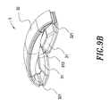
- FIG. 9B illustrates a schematic folding view of the third preferred embodiment of the mountable multi-directional audio device of the present invention.
- FIG. 10A illustrates a schematic sectional view of the broadcasting device of the third preferred embodiment of the mountable multi-directional audio device of the present invention
- FIG. 10B illustrates a schematic sounding view of the broadcasting device of the third preferred embodiment of the mountable multi-directional audio device of the present invention
- FIG. 11 illustrates a schematic application view of the third preferred embodiment of the mountable multi-directional audio device of the present invention.
- FIG. 12 illustrates a schematic 3-D structural view of a fourth preferred embodiment of the mountable multi-directional audio device of the present invention.
- FIG. 13 illustrates a schematic sectional view of the broadcasting device of the fourth preferred embodiment of the mountable multi-directional audio device of the present invention
- FIG. 14 illustrates a schematic application view of the fourth preferred embodiment of the mountable multi-directional audio device of the present invention.
- FIG. 15 illustrates a schematic rotation view of a fifth preferred embodiment of the mountable multi-directional audio device of the present invention.
- FIG. 16 illustrates a schematic extending view of a sixth preferred embodiment of the mountable multi-directional audio device of the present invention
- FIG. 1A and FIG. 1B illustrate a schematic 3-D structural view of a first preferred embodiment of the mountable multi-directional audio device of the present invention and a schematic folding view of the first preferred embodiment of the mountable multi-directional audio device of the present invention respectively.
- the mountable multi-directional audio device 1 has two broadcasting devices 11 and one connecting member 12 , wherein the two ends of the connecting member 12 are extendable to connect with the broadcasting devices 11 .
- the broadcasting device 11 has at least one speaker 111 inside.
- the broadcasting device 11 has a sounding portion 1111 outwardly.
- a baffle plate 112 is disposed on the sounding portion 1111 , in which the baffle plate 112 can be dismantled or un-dismantled.
- at least one sound exit 113 is disposed between the edge of the baffle plate 112 and the sounding portion 1111 , so the sound from the sounding portion 1111 will be emitted through the sound exit 113 while the sounding portion 1111 of the speaker 111 is making sounds, as shown in FIG. 3B .
- the connecting member 12 has a folding structure 121 in order to allow the broadcasting device 11 , extended from the connecting member 12 , be folded and a folding angle of the broadcasting device 11 be adjusted for each side of the mountable multi-directional audio device 1 , so that the mountable multi-directional audio device 1 is able to be placed on a plain surface.
- Each side of the mountable multi-directional audio device 1 further comprises a sound box, an amplifier and a power management device inside, not shown in figure, and a battery or wireless device can be optionally adapted, wherein the amplifier is connected with the broadcasting device 11 , so that the mountable multi-directional audio device 1 is integrated.
- the mountable multi-directional audio device 1 of the present invention can be worn on not only a user's head, but also a user's neck or shoulders. As shown in FIG. 5 , the mountable multi-directional audio device 1 is worn on the neck of the user 2 .
- the broadcasting device may have the sounding portion 1111 inwardly as well.
- FIG. 6A and FIG. 6B illustrate a schematic 3-D structural view of a second preferred embodiment of the mountable multi-directional audio device of the present invention and a schematic folding view of the second preferred embodiment of the mountable multi-directional audio device of the present invention respectively.
- the mechanism of the second preferred embodiment is the same as the mechanism of the first preferred embodiment. The only difference is that the sounding portion 1111 of the speaker 111 in the second preferred embodiment is disposed at the inner surface of the broadcasting device 11 , as shown in FIG. 7 .
- the sound from the sound portions 1111 is spread to the inner side of the broadcasting device 11 and goes out through the sound exits 113 . Therefore, there is no necessary to position the sounding portions 1111 toward the user's ears, and the sound from the sounding portions 1111 of the speaker 111 is still heard, as shown in FIG. 8 .
- the mountable multi-directional audio device 3 could have only a downward sound exit 313 between the side of the dismantled or un-dismantled baffle plate 312 and the sounding portion 3111 .
- FIG. 9A and FIG. 9B which point out a third preferred embodiment.
- the mountable multi-directional audio device 3 has two broadcasting devices 31 and one connecting member 32 .
- the two ends of the connecting member 32 are connected with the broadcasting device 31
- the broadcasting device 31 has at least one speaker 311 inside.
- the broadcasting device 31 has a sounding portion 3111 outwardly, and a dismantled baffle plate or un-dismantled baffle plate 312 is disposed on the sounding portion 3111 of the broadcasting device 31 .
- the downward sound exit 313 is disposed between the side of the baffle plate 312 and the sounding portion 3111 , and the sound from the sounding portion 3111 may be reflected by the baffle plate 312 and emitted toward the sound exit 313 while the sounding portion 3111 is making sounds, as shown in FIG. 10B .
- a case can be disposed on the surface of the broadcasting device 31 , not shown in figure, and another case can be disposed on the surface of the connecting member 32 , not shown in figure.
- Each side of the mountable multi-directional audio device 3 further comprises a sound box, an amplifier and a power management device inside, not shown in figure, wherein the amplifier is connected with the broadcasting device 11 , so that the mountable multi-directional audio device 1 is integrated.
- a battery or a wired or wireless sound signal receiving device can be optionally adapted by the mountable multi-directional audio device 3 , not shown in figure.
- the broadcasting device 31 may have one sounding portion 3111 inwardly as well, as shown in FIG. 12 and FIG. 13 , which illustrate a schematic structural view of a fourth preferred embodiment of the present invention and a schematic sectional view of the fourth preferred embodiment of the present invention.
- the mechanism of the fourth preferred embodiment is the same as the mechanism of the third preferred embodiment. The only difference is that the sounding portion 3111 of the speaker 311 in the fourth preferred embodiment is disposed inwardly, and the sound exit 313 between the side of the baffle plate 312 and the sounding portion 3111 is disposed inwardly as well, as shown in FIG. 13 . As shown in FIG.
- a rotation mechanism 33 is disposed between the connecting member 32 and the broadcasting device 31 , and therefore the broadcasting device 31 is capable of rotating toward different directions and positioning, as shown in FIG. 15 .
- a stretching mechanism 34 is disposed between the connecting member 32 and the broadcasting device 11 in order to allow the distance between the connecting member 32 and the broadcasting device 31 be variable, as shown in FIG. 16 .
- the present invention provides the mountable multi-directional audio device has following advantages listed below:
Abstract
A mountable multi-directional audio device comprises at least one broadcasting device, which has a sounding portion outwardly; and at least one connecting member, the any end of the connecting member is connected with the broadcasting device.
Description
1. Field of the Invention
The present invention relates to a mountable multi-directional audio device, more particularly, to an audio device that is worn on the body of a user.
2. Description of the Prior Art
Nowadays, earphones project sound to its surroundings via internal speakers. There are two types of earphones, one worn in the ears (ear wearing), and the other worn over the head (head wearing). The ear wearing earphones are worn with direct contact to the ear and is very close to the tympanic membrane, thus long-term usage of such earphones may cause damage to soft tissue in the ear.
Both of the ear wearing earphones and the head wearing earphones have their own pros and cons. However, because both of the earphones mentioned above project sounddirectly to a user's ears, when a user uses such earphones, the user may not be able to hear other sounds from the environment, such as alert sounds. Therefore, it can sometimes be very dangerous to the user.
In addition, speakers cannot be worn on a user due to their volumes and weights, so it would not be practical to use such speakers to slove the saftey problems caused by earphones.
Therefore, creating an audio device that can be worn on a user, in which the user hears sound smoothly without covering the user's ears would be the best solution to the safety problems caused by earphones.
The main objective of the present invention is to provide a mountable multi-directional audio device, which can be worn on the head, neck or shoulders of a user, so as to avoid the disadvantages of speakers and earphones. For example, speakers cannot be carried on, when earphones are used for a long time, they can damage the user's ears, and users may be distracted when they use earphones.
To achieve the objective, the mountable multi-directional audio device of the present invention comprises at least one broadcasting device 11 and one connecting member 12. Each end of the connecting member 12 is connected to the broadcasting device 11. The broadcasting device 11 has a sounding portion 1111, and a removable or an irremovable baffle plate 112 is disposed at the sounding portion 1111. At least one sound exit 113, which allows the sounding portion 1111 to emit sound, is disposed between the edge of the baffle plate 112 and the sounding portion 1111.
Particularly, the broadcasting device 11 has a sounding portion 1111 outwardly or inwardly.
Particularly, the broadcasting device 11 has at least one speaker 111 inside.
Particularly, a removable or an irremovable baffle plate 112 is disposed at the sounding portion 1111 of the broadcasting device 11, and at least one sound exit 113, which allows the sounding portion 1111 to emit sound, is disposed between the edge of the baffle plate 112 and the sounding portion 1111.
Particularly, a case can be disposed on the surface of the broadcasting device 11. In addition, another case can be disposed on the surface of the connecting member 12.
Particularly, the connecting member 12 has a folding structure 121 to make the broadcasting device 11, extended from the connecting member 12, be folded, and a folding angle of the broadcasting device 11 can be adjusted.
Particularly, an adjusting mechanism is disposed between the connecting member 12 and the broadcasting device 11 in order to allow the broadcasting device 11 be turned toward different directions and positioned.
Particularly, a stretching mechanism 14 is disposed between the connecting member 12 and the broadcasting device 11 in order to allow the length between the connecting member 12 and the broadcasting device 11 be variable.
Particularly, the mountable multi-directional audio device further comprises a sound box, an amplifier and a power management device inside.
Particularly, the mountable multi-directional audio device further accommodates a battery internally.
Particularly, the mountable multi-directional audio device further accommodates a wired or wireless sound signal receiving device internally.
Other and further features, advantages, and benefits of the invention will become apparent in the following description taken in conjunction with the following drawings. It is to be understood that the foregoing general description and following detailed description are exemplary and explanatory but are not to be restrictive of the invention. The accompanying drawings are incorporated in and constitute a part of this application and, together with the description, serve to explain the principles of the invention in general terms. Like numerals refer to like parts throughout the disclosure.
The objectives, spirits, and advantages of the preferred embodiments of the present invention will be readily understood by the accompanying drawings and detailed descriptions, wherein:
Following preferred embodiments and figures will be described in detail so as to achieve aforesaid objectives.
With references to FIG. 1A and FIG. 1B , FIG. 1A and FIG. 1B illustrate a schematic 3-D structural view of a first preferred embodiment of the mountable multi-directional audio device of the present invention and a schematic folding view of the first preferred embodiment of the mountable multi-directional audio device of the present invention respectively. As shown in figures, the mountable multi-directional audio device 1 has two broadcasting devices 11 and one connecting member 12, wherein the two ends of the connecting member 12 are extendable to connect with the broadcasting devices 11. The broadcasting device 11 has at least one speaker 111 inside. As shown in FIG. 3A , the broadcasting device 11 has a sounding portion 1111 outwardly. In addition, a baffle plate 112 is disposed on the sounding portion 1111, in which the baffle plate 112 can be dismantled or un-dismantled. As shown in FIG. 2A and FIG. 2B , at least one sound exit 113 is disposed between the edge of the baffle plate 112 and the sounding portion 1111, so the sound from the sounding portion 1111 will be emitted through the sound exit 113 while the sounding portion 1111 of the speaker 111 is making sounds, as shown in FIG. 3B .
Additionally, the connecting member 12 has a folding structure 121 in order to allow the broadcasting device 11, extended from the connecting member 12, be folded and a folding angle of the broadcasting device 11 be adjusted for each side of the mountable multi-directional audio device 1, so that the mountable multi-directional audio device 1 is able to be placed on a plain surface.
Furthermore, a case can be disposed on the surface of the broadcasting device 11, not shown in figure, and another case can be deposed on the surface of the connecting member 12, not shown in figure. Each side of the mountable multi-directional audio device 1 further comprises a sound box, an amplifier and a power management device inside, not shown in figure, and a battery or wireless device can be optionally adapted, wherein the amplifier is connected with the broadcasting device 11, so that the mountable multi-directional audio device 1 is integrated.
As shown in FIG. 4 , when a user 2 puts on the mountable multi-directional audio device 1 above the user's ears, sound from the sounding portion 1111 is blocked by the dismantled baffle plate or un-dismantled baffle plate 112, and consequently the sound is emitted through the sound exits 113. Hence, there is no necessary to position the sound portions 1111 toward the ears of the user 2, and the sound from the sounding portions 1111 of the speakers 111 is still heard. The mountable multi-directional audio device 1 of the present invention can be worn on not only a user's head, but also a user's neck or shoulders. As shown in FIG. 5 , the mountable multi-directional audio device 1 is worn on the neck of the user 2.
In addition to disposing the sounding portion 1111 on the broadcasting device 11 outside, the broadcasting device may have the sounding portion 1111 inwardly as well. As shown in FIG. 6A and FIG. 6B , FIG. 6A and FIG. 6B illustrate a schematic 3-D structural view of a second preferred embodiment of the mountable multi-directional audio device of the present invention and a schematic folding view of the second preferred embodiment of the mountable multi-directional audio device of the present invention respectively. The mechanism of the second preferred embodiment is the same as the mechanism of the first preferred embodiment. The only difference is that the sounding portion 1111 of the speaker 111 in the second preferred embodiment is disposed at the inner surface of the broadcasting device 11, as shown in FIG. 7 . Hence, the sound from the sound portions 1111 is spread to the inner side of the broadcasting device 11 and goes out through the sound exits 113. Therefore, there is no necessary to position the sounding portions 1111 toward the user's ears, and the sound from the sounding portions 1111 of the speaker 111 is still heard, as shown in FIG. 8 .
Other than the first preferred embodiment and the second preferred embodiment, the mountable multi-directional audio device 3 could have only a downward sound exit 313 between the side of the dismantled or un-dismantled baffle plate 312 and the sounding portion 3111. As shown in FIG. 9A and FIG. 9B , which point out a third preferred embodiment. The mountable multi-directional audio device 3 has two broadcasting devices 31 and one connecting member 32. The two ends of the connecting member 32 are connected with the broadcasting device 31, and the broadcasting device 31 has at least one speaker 311 inside. As shown in FIG. 10A , the broadcasting device 31 has a sounding portion 3111 outwardly, and a dismantled baffle plate or un-dismantled baffle plate 312 is disposed on the sounding portion 3111 of the broadcasting device 31. As shown in FIG. 10A and FIG. 10B , the downward sound exit 313 is disposed between the side of the baffle plate 312 and the sounding portion 3111, and the sound from the sounding portion 3111 may be reflected by the baffle plate 312 and emitted toward the sound exit 313 while the sounding portion 3111 is making sounds, as shown in FIG. 10B .
As shown in FIG. 11 , when a user 2 puts on the mountable multi-directional audio device 3 above the user's ears, sound from the sounding portion 3111 may be reflected by the baffle plate 312, and consequently the sound may be emitted through the sound exits 313. Hence, there is no necessary to position the sound portions 3111 toward the ears of the user 2, and the sound from the sounding portions 3111 of the speakers 311 is still heard.
Moreover, a case can be disposed on the surface of the broadcasting device 31, not shown in figure, and another case can be disposed on the surface of the connecting member 32, not shown in figure. Each side of the mountable multi-directional audio device 3 further comprises a sound box, an amplifier and a power management device inside, not shown in figure, wherein the amplifier is connected with the broadcasting device 11, so that the mountable multi-directional audio device 1 is integrated. A battery or a wired or wireless sound signal receiving device can be optionally adapted by the mountable multi-directional audio device 3, not shown in figure.
In addition to disposing the sounding portion 3111 on the broadcasting device 31 outwardly, the broadcasting device 31 may have one sounding portion 3111 inwardly as well, as shown in FIG. 12 and FIG. 13 , which illustrate a schematic structural view of a fourth preferred embodiment of the present invention and a schematic sectional view of the fourth preferred embodiment of the present invention. The mechanism of the fourth preferred embodiment is the same as the mechanism of the third preferred embodiment. The only difference is that the sounding portion 3111 of the speaker 311 in the fourth preferred embodiment is disposed inwardly, and the sound exit 313 between the side of the baffle plate 312 and the sounding portion 3111 is disposed inwardly as well, as shown in FIG. 13 . As shown in FIG. 14 , when the user 2 puts the mountable multi-directional audio device 3 on the user's head, sound from the sounding portion 3111 is reflected by the baffle plate 312, and consequently the sound is emitted through the sound exits 313. Hence, there is no necessary to position the sound portions 3111 toward the ears of the user 2, the sound from the sounding portions 3111 of the speakers 311 is still heard.
Moreover, a rotation mechanism 33 is disposed between the connecting member 32 and the broadcasting device 31, and therefore the broadcasting device 31 is capable of rotating toward different directions and positioning, as shown in FIG. 15 . A stretching mechanism 34 is disposed between the connecting member 32 and the broadcasting device 11 in order to allow the distance between the connecting member 32 and the broadcasting device 31 be variable, as shown in FIG. 16 .
Compared to prior art, the present invention provides the mountable multi-directional audio device has following advantages listed below:
- 1. The mountable multi-directional audio device of the present invention is a headset audio device and able to let sound be broadcasted toward different directions so as to avoid the situation in that a user may be distracted when using earphones.
- 2. The mountable multi-directional audio device of the present invention is a headset audio device and able to let sound be broadcasted toward different directions so as to make a low possibility of damaging the ears of a user.
- 3. Each side of the mountable multi-directional audio device further comprises a sound box, an amplifier and a power management device inside, and in addition to that, a battery or a wired or wireless sound signal receiving device can be optionally adapted by the mountable multi-directional audio device, so the mountable multi-directional audio device is a multi-function and integrated audio device.
- 4. The mountable multi-directional audio device of the present invention can be folded and carry-on.
Although the invention has been disclosed and illustrated with reference to particular embodiments, the principles involved are susceptible for use in numerous other embodiments that will be apparent to persons skilled in the art. This invention is, therefore, to be limited only as indicated by the scope of the is appended claims.
Claims (18)
1. A mountable multi-directional audio device comprising:
two broadcasting devices (11), each of the two broadcasting devices 11 having a speaker (111) inside, a sounding portion (1111) of the speaker (111) disposed in each of the broadcasting devices (11) outwardly, an intact baffle plate (112) having at least two stands on the edges of the baffle plate (112) disposed on the sounding portion (1111), and at least one sound exit (113) formed between the edge of the baffle plate (112) and the sounding portion (1111), and the sound exit (113) allowing the sounding portion (1111) to emit sound;
one connecting member (12) having a first end and a second end, each end of the connecting member (12) being connected to one of the broadcasting devices 11; and
an adjusting mechanism (33) is disposed between the connecting member (12) and the broadcasting device (11) in order to allow the broadcasting device (11) be turned toward different directions and positioned.
2. The mountable multi-directional audio device according to claim 1 , wherein the baffle plate (112) is dismantled or un-dismantled.
3. The mountable multi-directional audio device according to claim 1 , wherein a case is further disposed on the surface of the broadcasting device (11).
4. The mountable multi-directional audio device according to claim 1 , wherein the connecting member (12) has a folding structure (121) in order to let the broadcasting device (11), extended from the connecting member (21), be folded and a folding angle of the broadcasting device (11) be adjusted.
5. The mountable multi-directional audio device according to claim 1 further comprising a sound box, an amplifier and a power management device inside.
6. The mountable multi-directional audio device according to claim 1 accommodating a battery internally.
7. The mountable multi-directional audio device according to claim 1 accommodating a wired or wireless sound signal receiving device internally.
8. The mountable multi-directional audio device according to claim 1 , wherein a case is disposed on the surface of the connecting member (12).
9. The mountable multi-directional audio device according to claim 1 , wherein a stretching mechanism (14) is disposed between the connecting member (12) and the broadcasting device (11) in order to allow the length between the connecting member (12) and the broadcasting device (11) be variable.
10. A mountable multi-directional audio device comprising:
two broadcasting device (31), each of the two broadcasting devices (31) having a speaker (311) inside, a sounding portion (3111) of the speaker (311) disposed in each of the broadcasting devices (31) inwardly, an intact baffle plate (312) having at least two stands on the edges of the baffle plate (312) disposed on the sounding portion (3111), and at least one sound exit (313) formed between the edge of the baffle plate (312) and the sounding portion (3111), and the sound exit (313) allowing the sounding portion (3111) to emit sound which has a sounding portion 3111 inwardly;
at least one connecting member (32) having a first end and a second end, the any each end of the connecting member (32) is being connected with to one of the broadcasting devices (31); and
an adjusting mechanism (33) is disposed between the connecting member (32) and the broadcasting device (31) in order to let allow the broadcasting device (31) be turned toward different directions and positioned.
11. The mountable multi-directional audio device according to claim 10 , wherein the baffle plate (312) is dismantled or un-dismantled.
12. The mountable multi-directional audio device according to claim 10 , wherein a case is disposed on the surface of the broadcasting device (31).
13. The mountable multi-directional audio device according to claim 10 , wherein the connecting member (32) has a folding structure (321) in order to allow the broadcasting device (31), extended from the connecting member (32), be folded and a folding angle of the broadcasting device (31) be adjusted.
14. The mountable multi-directional audio device according to claim 10 further comprising a sound box, an amplifier and a power management device inside.
15. The mountable multi-directional audio device according to claim 10 accommodating a battery internally.
16. The mountable multi-directional audio device according to claim 10 accommodating a wired or wireless sound signal receiving device internally.
17. The mountable multi-directional audio device according to claim 10 , wherein a case is disposed on the surface of the connecting member (32).
18. The mountable multi-directional audio device according to claim 10 , wherein a stretching mechanism (34) is disposed between the connecting member (32) and the broadcasting device (31) in order to allow the length between the connecting member (32) and the broadcasting device (31) be variable.
Priority Applications (1)
| Application Number | Priority Date | Filing Date | Title |
|---|---|---|---|
| US13/326,630 US8649547B2 (en) | 2011-12-15 | 2011-12-15 | Mountable multi-directional audio device |
Applications Claiming Priority (1)
| Application Number | Priority Date | Filing Date | Title |
|---|---|---|---|
| US13/326,630 US8649547B2 (en) | 2011-12-15 | 2011-12-15 | Mountable multi-directional audio device |
Publications (2)
| Publication Number | Publication Date |
|---|---|
| US20130156250A1 US20130156250A1 (en) | 2013-06-20 |
| US8649547B2 true US8649547B2 (en) | 2014-02-11 |
Family
ID=48610170
Family Applications (1)
| Application Number | Title | Priority Date | Filing Date |
|---|---|---|---|
| US13/326,630 Active US8649547B2 (en) | 2011-12-15 | 2011-12-15 | Mountable multi-directional audio device |
Country Status (1)
| Country | Link |
|---|---|
| US (1) | US8649547B2 (en) |
Cited By (4)
| Publication number | Priority date | Publication date | Assignee | Title |
|---|---|---|---|---|
| US9055795B2 (en) | 2012-03-29 | 2015-06-16 | Nicholas Stuart Larkin | Cable tethering neckpiece |
| WO2018076140A1 (en) * | 2016-10-24 | 2018-05-03 | 王丰硕 | 5ghz multichannel lossless wireless audio system |
| USD831000S1 (en) * | 2017-06-13 | 2018-10-16 | Razer (Asia-Pacific) Pte. Ltd. | Headset |
| USD899400S1 (en) * | 2018-02-27 | 2020-10-20 | Hewlett-Packard Development Company, L.P. | Headset |
Families Citing this family (35)
| Publication number | Priority date | Publication date | Assignee | Title |
|---|---|---|---|---|
| EP3035699B1 (en) * | 2013-08-13 | 2021-08-04 | Sony Group Corporation | Headphone-type acoustic device |
| CN203761575U (en) * | 2014-03-18 | 2014-08-06 | 王丰硕 | 5GHz wireless stereo sound equipment system |
| USD816635S1 (en) * | 2016-03-18 | 2018-05-01 | Bose Corporation | Audio device |
| USD797701S1 (en) * | 2016-03-18 | 2017-09-19 | Bose Corporation | Audio device |
| USD795836S1 (en) * | 2016-03-18 | 2017-08-29 | Bose Corporation | Audio device |
| USD815059S1 (en) * | 2016-08-02 | 2018-04-10 | Bose Corporation | Audio device |
| USD831607S1 (en) * | 2016-08-02 | 2018-10-23 | Bose Corporation | Audio device |
| USD815058S1 (en) * | 2016-08-02 | 2018-04-10 | Bose Corporation | Audio device |
| USD821352S1 (en) * | 2016-08-02 | 2018-06-26 | Bose Corporation | Audio device |
| USD811366S1 (en) | 2016-08-31 | 2018-02-27 | Harman International Industries, Incorporated | Wearable audio component |
| USD851625S1 (en) | 2016-08-31 | 2019-06-18 | Harman International Industries, Incorporated | Wearable audio component |
| US10237657B2 (en) | 2016-09-02 | 2019-03-19 | Apple Inc. | Wireless headset antennas |
| USD839236S1 (en) * | 2016-11-09 | 2019-01-29 | Muzik Inc. | Bone conductive audio headband |
| USD830994S1 (en) * | 2016-12-23 | 2018-10-16 | Samsung Electronics Co., Ltd. | Neckband earphone |
| USD844585S1 (en) * | 2016-12-27 | 2019-04-02 | Sony Corporation | Earphone |
| USD845270S1 (en) * | 2016-12-27 | 2019-04-09 | Sennheiser Electronic Gmbh & Co. Kg | Headset |
| USD831609S1 (en) * | 2016-12-28 | 2018-10-23 | Shenzhen Shuaixian Electronic Equipment Co., Ltd. | Neck strap wireless headset |
| USD818454S1 (en) * | 2017-03-31 | 2018-05-22 | Beijing Jin Rui De Lu Technology Co. Ltd. | Intelligent earphone |
| USD854512S1 (en) * | 2017-04-20 | 2019-07-23 | Shenzhen Shuaixian Electronic Equipment Co., Ltd. | Neck strap wireless headset |
| USD826896S1 (en) * | 2017-04-20 | 2018-08-28 | Shenzhen Shuaixian Electronic Equipment Co., Ltd. | Neck strap wireless headset |
| USD843968S1 (en) * | 2017-06-14 | 2019-03-26 | Qunru Li | Headset |
| USD842838S1 (en) * | 2017-09-29 | 2019-03-12 | Qunru Li | Headset |
| USD842837S1 (en) * | 2017-09-29 | 2019-03-12 | Qunru Li | Headset |
| USD843969S1 (en) * | 2017-10-06 | 2019-03-26 | Qunru Li | Headset |
| USD914634S1 (en) | 2017-10-17 | 2021-03-30 | Plantronics, Inc. | Communications headset |
| USD853987S1 (en) * | 2017-10-17 | 2019-07-16 | Plantronics, Inc. | Communications headset |
| USD899398S1 (en) * | 2018-12-19 | 2020-10-20 | YoungSik BAE | Headphone |
| USD892764S1 (en) * | 2019-01-18 | 2020-08-11 | Datafly Commerce Inc. | Headphones |
| JP1657870S (en) * | 2019-10-07 | 2020-04-20 | ||
| USD991215S1 (en) * | 2020-09-10 | 2023-07-04 | Huawei Technologies Co., Ltd. | Earphone |
| USD968360S1 (en) * | 2021-03-04 | 2022-11-01 | Kazuma Omura | Electronic neckset |
| JP1703850S (en) * | 2021-05-10 | 2022-01-04 | ||
| JP1703849S (en) * | 2021-05-10 | 2022-01-04 | ||
| JP1703848S (en) * | 2021-05-10 | 2022-01-04 | ||
| USD1009287S1 (en) * | 2022-06-06 | 2023-12-26 | Ontel Products Corporation | Neck heater |
Citations (20)
| Publication number | Priority date | Publication date | Assignee | Title |
|---|---|---|---|---|
| US2141423A (en) * | 1936-03-28 | 1938-12-27 | Magnavox Company Inc | Loudspeaker mounting |
| US4058688A (en) * | 1975-05-27 | 1977-11-15 | Matsushita Electric Industrial Co., Ltd. | Headphone |
| US6412593B1 (en) * | 1998-03-18 | 2002-07-02 | Nct Group, Inc. | Cushioned earphones |
| US6993143B2 (en) * | 2003-09-08 | 2006-01-31 | Brookstone Purchasing, Inc | Foldable headphones |
| US20060104471A1 (en) * | 2004-10-20 | 2006-05-18 | Sony Corporation | Headphone apparatus |
| US7155025B1 (en) * | 2002-08-30 | 2006-12-26 | Weffer Sergio W | Surround sound headphone system |
| US20080075314A1 (en) * | 2006-09-06 | 2008-03-27 | Chi-Tsan Chang | Sound-box type earphone housing, headset with sound-box type earphone housings |
| US20080122736A1 (en) * | 1993-10-22 | 2008-05-29 | Kopin Corporation | Portable communication display device |
| US20080170738A1 (en) * | 2007-01-16 | 2008-07-17 | Sony Ericsson Mobile Communications Ab | Adjustable earphones for portable devices |
| US7426282B1 (en) * | 2000-09-06 | 2008-09-16 | Us Design & Productions | Head set speaker and stereo playing device |
| US20090147982A1 (en) * | 2007-12-06 | 2009-06-11 | Rohm Co., Ltd. | Headphone set and headphone cable |
| US20090285435A1 (en) * | 2008-05-14 | 2009-11-19 | Nixon, Inc. | Headphones |
| US20100067714A1 (en) * | 2008-09-16 | 2010-03-18 | Kuo-Shu Cheng | Headphones switchable to a sound box mode of operation |
| US20100177907A1 (en) * | 2009-01-14 | 2010-07-15 | Sony Corporation | Headphones and earmuffs |
| US20120093351A1 (en) * | 2007-01-10 | 2012-04-19 | Allan Amsel | Combined headphone set and portable speaker assembly |
| US8213632B2 (en) * | 2006-02-01 | 2012-07-03 | Sony Corporation | Electroacoustic transducer and ear speaker device |
| US20120275615A1 (en) * | 2010-01-06 | 2012-11-01 | Skullcandy, Inc. | Dj mixing headphones |
| US20130003984A1 (en) * | 2011-06-29 | 2013-01-03 | MS Electronics LLC | Headphones with expandable speaker enclosures |
| US8371417B2 (en) * | 2010-07-22 | 2013-02-12 | JVC Kenwood Corporation | Headphones |
| US8538059B2 (en) * | 2006-12-05 | 2013-09-17 | Sony Corporation | Ear speaker device |
-
2011
- 2011-12-15 US US13/326,630 patent/US8649547B2/en active Active
Patent Citations (20)
| Publication number | Priority date | Publication date | Assignee | Title |
|---|---|---|---|---|
| US2141423A (en) * | 1936-03-28 | 1938-12-27 | Magnavox Company Inc | Loudspeaker mounting |
| US4058688A (en) * | 1975-05-27 | 1977-11-15 | Matsushita Electric Industrial Co., Ltd. | Headphone |
| US20080122736A1 (en) * | 1993-10-22 | 2008-05-29 | Kopin Corporation | Portable communication display device |
| US6412593B1 (en) * | 1998-03-18 | 2002-07-02 | Nct Group, Inc. | Cushioned earphones |
| US7426282B1 (en) * | 2000-09-06 | 2008-09-16 | Us Design & Productions | Head set speaker and stereo playing device |
| US7155025B1 (en) * | 2002-08-30 | 2006-12-26 | Weffer Sergio W | Surround sound headphone system |
| US6993143B2 (en) * | 2003-09-08 | 2006-01-31 | Brookstone Purchasing, Inc | Foldable headphones |
| US20060104471A1 (en) * | 2004-10-20 | 2006-05-18 | Sony Corporation | Headphone apparatus |
| US8213632B2 (en) * | 2006-02-01 | 2012-07-03 | Sony Corporation | Electroacoustic transducer and ear speaker device |
| US20080075314A1 (en) * | 2006-09-06 | 2008-03-27 | Chi-Tsan Chang | Sound-box type earphone housing, headset with sound-box type earphone housings |
| US8538059B2 (en) * | 2006-12-05 | 2013-09-17 | Sony Corporation | Ear speaker device |
| US20120093351A1 (en) * | 2007-01-10 | 2012-04-19 | Allan Amsel | Combined headphone set and portable speaker assembly |
| US20080170738A1 (en) * | 2007-01-16 | 2008-07-17 | Sony Ericsson Mobile Communications Ab | Adjustable earphones for portable devices |
| US20090147982A1 (en) * | 2007-12-06 | 2009-06-11 | Rohm Co., Ltd. | Headphone set and headphone cable |
| US20090285435A1 (en) * | 2008-05-14 | 2009-11-19 | Nixon, Inc. | Headphones |
| US20100067714A1 (en) * | 2008-09-16 | 2010-03-18 | Kuo-Shu Cheng | Headphones switchable to a sound box mode of operation |
| US20100177907A1 (en) * | 2009-01-14 | 2010-07-15 | Sony Corporation | Headphones and earmuffs |
| US20120275615A1 (en) * | 2010-01-06 | 2012-11-01 | Skullcandy, Inc. | Dj mixing headphones |
| US8371417B2 (en) * | 2010-07-22 | 2013-02-12 | JVC Kenwood Corporation | Headphones |
| US20130003984A1 (en) * | 2011-06-29 | 2013-01-03 | MS Electronics LLC | Headphones with expandable speaker enclosures |
Cited By (5)
| Publication number | Priority date | Publication date | Assignee | Title |
|---|---|---|---|---|
| US9055795B2 (en) | 2012-03-29 | 2015-06-16 | Nicholas Stuart Larkin | Cable tethering neckpiece |
| WO2018076140A1 (en) * | 2016-10-24 | 2018-05-03 | 王丰硕 | 5ghz multichannel lossless wireless audio system |
| USD831000S1 (en) * | 2017-06-13 | 2018-10-16 | Razer (Asia-Pacific) Pte. Ltd. | Headset |
| USD868030S1 (en) | 2017-06-13 | 2019-11-26 | Razer (Asia-Pacific) Pte. Ltd. | Headset |
| USD899400S1 (en) * | 2018-02-27 | 2020-10-20 | Hewlett-Packard Development Company, L.P. | Headset |
Also Published As
| Publication number | Publication date |
|---|---|
| US20130156250A1 (en) | 2013-06-20 |
Similar Documents
| Publication | Publication Date | Title |
|---|---|---|
| US8649547B2 (en) | Mountable multi-directional audio device | |
| USD852784S1 (en) | Wireless pair of earbuds | |
| US10531175B2 (en) | Headphone system with detachable earbud speakers | |
| USD811362S1 (en) | Headphone headset | |
| US20120275635A1 (en) | Earphone with mutually obliquely oriented sound holes | |
| JP4994497B2 (en) | Device called improved ear unit | |
| WO2018079576A1 (en) | Bone-conduction headset | |
| WO2009116272A1 (en) | Bone conduction speaker and listening device using same | |
| US20150382099A1 (en) | Headphone structure for adjusting audio frequencies | |
| US20170064436A1 (en) | Headphone | |
| US20060126882A1 (en) | Earphone | |
| WO2018058878A1 (en) | Earphone cover and earphone having same | |
| WO2007133055A1 (en) | Bone conduction headset | |
| US10582301B2 (en) | Speaker device with drone cones and curved support member | |
| US10959009B2 (en) | Wearable personal acoustic device having outloud and private operational modes | |
| US20140328508A1 (en) | Hat with sound playing device | |
| JP2007158924A (en) | Headphone unit | |
| CN104254036A (en) | Headset | |
| CN102780939B (en) | Hanging and wearing type multi-directional audible device | |
| KR100905252B1 (en) | Receiving device with opening structure | |
| SE1550627A1 (en) | A headset with a pair of listening devices and a behind the head resilient cord | |
| US9609413B2 (en) | Headphone | |
| US10015576B1 (en) | Headphones with coordinated external illumination | |
| US20170180836A1 (en) | Loudspeaker and Microphone Device | |
| US20120308068A1 (en) | Head multi-directional audio device |
Legal Events
| Date | Code | Title | Description |
|---|---|---|---|
| AS | Assignment |
Owner name: JAZZ HIPSTER CORPORATION, TAIWAN Free format text: ASSIGNMENT OF ASSIGNORS INTEREST;ASSIGNORS:HSU HUANG, YUEH-HUA;HSU, WEN-CHUAN;CHEN, CHUN-TI;SIGNING DATES FROM 20111208 TO 20111209;REEL/FRAME:027391/0544 |
|
| STCF | Information on status: patent grant |
Free format text: PATENTED CASE |
|
| FPAY | Fee payment |
Year of fee payment: 4 |
|
| MAFP | Maintenance fee payment |
Free format text: PAYMENT OF MAINTENANCE FEE, 8TH YR, SMALL ENTITY (ORIGINAL EVENT CODE: M2552); ENTITY STATUS OF PATENT OWNER: SMALL ENTITY Year of fee payment: 8 |