US8649130B2 - Motor driving apparatus having fault diagnostic function - Google Patents
Motor driving apparatus having fault diagnostic function Download PDFInfo
- Publication number
- US8649130B2 US8649130B2 US13/025,210 US201113025210A US8649130B2 US 8649130 B2 US8649130 B2 US 8649130B2 US 201113025210 A US201113025210 A US 201113025210A US 8649130 B2 US8649130 B2 US 8649130B2
- Authority
- US
- United States
- Prior art keywords
- phase
- converter
- sum
- overcurrent
- power
- Prior art date
- Legal status (The legal status is an assumption and is not a legal conclusion. Google has not performed a legal analysis and makes no representation as to the accuracy of the status listed.)
- Active, expires
Links
Images


Classifications
-
- H—ELECTRICITY
- H02—GENERATION; CONVERSION OR DISTRIBUTION OF ELECTRIC POWER
- H02H—EMERGENCY PROTECTIVE CIRCUIT ARRANGEMENTS
- H02H7/00—Emergency protective circuit arrangements specially adapted for specific types of electric machines or apparatus or for sectionalised protection of cable or line systems, and effecting automatic switching in the event of an undesired change from normal working conditions
- H02H7/08—Emergency protective circuit arrangements specially adapted for specific types of electric machines or apparatus or for sectionalised protection of cable or line systems, and effecting automatic switching in the event of an undesired change from normal working conditions for dynamo-electric motors
- H02H7/0833—Emergency protective circuit arrangements specially adapted for specific types of electric machines or apparatus or for sectionalised protection of cable or line systems, and effecting automatic switching in the event of an undesired change from normal working conditions for dynamo-electric motors for electric motors with control arrangements
- H02H7/0838—Emergency protective circuit arrangements specially adapted for specific types of electric machines or apparatus or for sectionalised protection of cable or line systems, and effecting automatic switching in the event of an undesired change from normal working conditions for dynamo-electric motors for electric motors with control arrangements with H-bridge circuit
-
- H—ELECTRICITY
- H02—GENERATION; CONVERSION OR DISTRIBUTION OF ELECTRIC POWER
- H02P—CONTROL OR REGULATION OF ELECTRIC MOTORS, ELECTRIC GENERATORS OR DYNAMO-ELECTRIC CONVERTERS; CONTROLLING TRANSFORMERS, REACTORS OR CHOKE COILS
- H02P29/00—Arrangements for regulating or controlling electric motors, appropriate for both AC and DC motors
- H02P29/02—Providing protection against overload without automatic interruption of supply
- H02P29/024—Detecting a fault condition, e.g. short circuit, locked rotor, open circuit or loss of load
- H02P29/0241—Detecting a fault condition, e.g. short circuit, locked rotor, open circuit or loss of load the fault being an overvoltage
-
- H—ELECTRICITY
- H02—GENERATION; CONVERSION OR DISTRIBUTION OF ELECTRIC POWER
- H02P—CONTROL OR REGULATION OF ELECTRIC MOTORS, ELECTRIC GENERATORS OR DYNAMO-ELECTRIC CONVERTERS; CONTROLLING TRANSFORMERS, REACTORS OR CHOKE COILS
- H02P29/00—Arrangements for regulating or controlling electric motors, appropriate for both AC and DC motors
- H02P29/02—Providing protection against overload without automatic interruption of supply
- H02P29/024—Detecting a fault condition, e.g. short circuit, locked rotor, open circuit or loss of load
- H02P29/027—Detecting a fault condition, e.g. short circuit, locked rotor, open circuit or loss of load the fault being an over-current
-
- G—PHYSICS
- G01—MEASURING; TESTING
- G01R—MEASURING ELECTRIC VARIABLES; MEASURING MAGNETIC VARIABLES
- G01R19/00—Arrangements for measuring currents or voltages or for indicating presence or sign thereof
- G01R19/10—Measuring sum, difference or ratio
-
- H—ELECTRICITY
- H02—GENERATION; CONVERSION OR DISTRIBUTION OF ELECTRIC POWER
- H02H—EMERGENCY PROTECTIVE CIRCUIT ARRANGEMENTS
- H02H1/00—Details of emergency protective circuit arrangements
- H02H1/0038—Details of emergency protective circuit arrangements concerning the connection of the detecting means, e.g. for reducing their number
-
- H—ELECTRICITY
- H02—GENERATION; CONVERSION OR DISTRIBUTION OF ELECTRIC POWER
- H02H—EMERGENCY PROTECTIVE CIRCUIT ARRANGEMENTS
- H02H3/00—Emergency protective circuit arrangements for automatic disconnection directly responsive to an undesired change from normal electric working condition with or without subsequent reconnection ; integrated protection
- H02H3/08—Emergency protective circuit arrangements for automatic disconnection directly responsive to an undesired change from normal electric working condition with or without subsequent reconnection ; integrated protection responsive to excess current
- H02H3/10—Emergency protective circuit arrangements for automatic disconnection directly responsive to an undesired change from normal electric working condition with or without subsequent reconnection ; integrated protection responsive to excess current additionally responsive to some other abnormal electrical conditions
- H02H3/105—Emergency protective circuit arrangements for automatic disconnection directly responsive to an undesired change from normal electric working condition with or without subsequent reconnection ; integrated protection responsive to excess current additionally responsive to some other abnormal electrical conditions responsive to excess current and fault current to earth
Definitions
- the present invention relates to a motor driving apparatus having a fault diagnostic function.
- a motor driving apparatus which is connected to a three-phase AC power supply and which comprises an AC/DC converter for converting three-phase AC power supplied from the three-phase AC power supply into DC power and a DC/AC converter for converting the DC power output from the AC/DC converter into three-phase AC power for supply to a motor.
- the apparatus can reliably detect any overcurrent occurring in the DC/AC converter and can also identify whether the cause is a ground fault or a phase-to-phase short circuit.
- the overcurrent can be detected by one of the three sensors, and if the sum of the currents detected by the three current sensors is not zero, it is determined that the cause is a ground fault, but if the sum is zero, it is determined that the cause is a phase-to-phase short circuit.
- the operation of the apparatus has to be stopped in the event of the occurrence of an overcurrent alarm, and the insulation resistance of the motor and power lines has to be checked in order to determine whether the cause is a ground fault or a phase-to-phase short circuit. Further, if the ground fault is intermittent, it is difficult to identify the cause.
- JP7-239359A discloses an apparatus that uses one or two current sensors and that provides protection against ground faults by detecting the presence or absences of a ground fault before starting the operation by applying a ground-fault detecting control signal to the AC/DC converter.
- a ground fault and a phase-to-phase short circuit.
- JP4-10536A discloses an apparatus in which a zero phase current detector is provided between the three-phase AC power supply and the apparatus, with provisions made to stop the operation of the inverter apparatus upon detection of a ground fault.
- a zero phase current detector is provided between the three-phase AC power supply and the apparatus, with provisions made to stop the operation of the inverter apparatus upon detection of a ground fault.
- no description is given of the detection of a phase-to-phase short circuit.
- JP63-85380A cited in JP7-239359A discloses a method that provides a detector for detecting the DC current input to the inverter apparatus, wherein the current detection pattern generated when a test control signal was applied to the inverter apparatus before starting the operation is compared with a known pattern to detect the presence or absence of a ground fault or a short circuit fault.
- this method not only has the drawback that the detected current contains a reactive current that flows through free wheel diodes in the inverter apparatus, as described in JP7-239359A (paragraph 0004), but also has the problem that a ground fault or a phase-to-phase short circuit that occurs after starting the operation or a ground fault that occurs intermittently during the operation cannot be detected.
- a motor driving apparatus having a fault diagnostic function capable of detecting during operation a ground fault and a phase-to-phase short circuit by distinguishing one from the other.
- a motor driving apparatus comprising an AC/DC converter for converting three-phase AC power supplied from a three-phase AC power supply into DC power and a DC/AC converter for converting the DC power output from the AC/DC converter into three-phase AC power for supply to a motor
- the motor driving apparatus further comprises: a sum current detector which detects the sum of currents flowing from the three-phase AC power supply through the AC/DC converter to the DC/AC converter; an overcurrent detector which detects overcurrent on an output current of the DC/AC converter; and a determining unit which, when overcurrent is detected by the overcurrent detector, determines that a ground fault has occurred if the sum of currents detected by the sum current detector can be judged to be not zero, but determines that a phase-to-phase short circuit has occurred if the sum of currents detected by the sum current detector can be judged to be zero.
- the increase in cost is less than would be if an extra current sensor was added to each inverter in order to make the ground-fault/phase-to-phase short circuit determination.
- FIG. 1 is a diagram explaining a phase-to-phase short circuit
- FIG. 2 is a waveform diagram explaining overcurrent occurring due to the phase-to-phase short circuit
- FIG. 3 is a diagram explaining a ground fault
- FIG. 4 is a diagram explaining overcurrent occurring due to the ground fault
- FIG. 5 is a diagram showing the configuration of a motor driving apparatus according to one embodiment of the present invention.
- FIG. 6 is a diagram showing the configuration of a motor driving apparatus according to an alternative embodiment of the present invention.
- FIG. 7 is a diagram showing the configuration of a motor driving apparatus according to another alternative embodiment of the present invention.
- FIG. 8 is a diagram showing the configuration of a motor driving apparatus according to still another alternative embodiment of the present invention.
- FIG. 9 is a diagram showing the configuration of a motor driving apparatus according to yet another alternative embodiment of the present invention.
- phase-to-phase short circuit When a short circuit (a phase-to-phase short circuit) momentarily occurs, for example, between the S phase and T phase, at the output side of a DC/AC converter 10 , as shown in FIG. 1 , overcurrent 12 and overcurrent 14 appear on the S-phase current I S and T-phase current I T , respectively, as shown in FIG. 2 .
- phase-to-phase short circuit since there is no current return via ground, the following relationship holds between the phase currents I R , I S , and I T .
- I R +I S +I T 0 (1)
- the DC/AC converter 10 is provided at the output side with three current sensors for detecting the three phase currents independently of each other, whether the short circuit is a ground fault or a phase-to-phase short circuit can be determined by taking the sum of the currents and checking whether the relation defined by equation (1) holds or not.
- generally only two sensors are provided in order to reduce the cost, and the remaining one of the three phase currents is obtained through calculation by assuming that the sum of the three phase currents is zero.
- using only two current sensors it is not possible to distinguish between the ground fault and the phase-to-phase short circuit. In the example shown in FIG.
- FIG. 5 shows the configuration of a motor driving apparatus, according to a first embodiment of the present invention, that has a function to detect the occurrence of overcurrent and to determine whether the cause is a phase-to-phase short circuit or a ground fault.
- An AC/DC converter 18 converts three-phase AC power supplied from a three-phase AC power supply 20 into DC power for output.
- a DC/AC converter 10 converts the DC power output from the AC/DC converter 18 into frequency variable three-phase AC power for output. Portions for controlling the transistors in the DC/AC converter 10 and AC/DC converter 18 are not shown here.
- a zero phase current detector 22 detects the sum of the three-phase AC currents supplied from the three-phase AC power supply to the AC/DC converter 18 .
- Current sensors 24 and 26 detect two of the three-phase AC currents output from the DC/AC converter 10 .
- An overcurrent detector 28 detects overcurrent based on the currents detected by the current sensors 24 and 26 .
- a ground-fault/short-circuit determining unit 30 determines, based on the current detected by the zero phase current detector 22 , whether the cause of the overcurrent is a ground fault or a phase-to-phase short circuit.
- the ground-fault/phase-to-phase short-circuit determining unit 30 determines that the cause of the overcurrent is a phase-to-phase short circuit; on the other hand, if the sum of the currents is not so small as to be judged to be equal to zero, it is determined that the cause of the overcurrent is a ground fault.
- the ground-fault/phase-to-phase short-circuit determining unit 30 can detect the occurrence of the ground fault.
- a clamp-on sensor or the like that detects current by detecting the magnetic field around the current using a Hall element. That is, by passing all of the three power lines through the detection ring of the clamp-on sensor, the sum of the currents can be detected, as in the case of the zero phase current detector.
- FIG. 6 shows an example in which, instead of detecting the sum of the three-phase AC currents at the input side by the zero phase current detector 22 , the three-phase AC currents at the input side are detected independently of each other by current sensors 32 , 34 , and 36 and are added together by an adder 38 to obtain the sum of the currents.
- FIG. 7 shows an example in which, as a means for detecting the sum of the currents at the input side, a clamp-on sensor 40 similar to the one described above is provided to detect the sum of the currents flowing on the two lines through which the DC power from the AC/DC converter 18 is supplied to the DC/AC converter 10 .
- FIG. 8 shows an example in which the current sensors 24 and 26 shown in the example of FIG. 5 are omitted and, instead, a current sensor 44 is provided which detects overcurrent by detecting the current flowing on one of the two lines through which the DC power from the AC/DC converter 18 is supplied to the DC/AC converter 10 via a smoothing capacitor 42 .
- a current sensor 44 is provided which detects overcurrent by detecting the current flowing on one of the two lines through which the DC power from the AC/DC converter 18 is supplied to the DC/AC converter 10 via a smoothing capacitor 42 .
- the means described with reference to FIG. 6 or 7 may be used instead of the current sensor 22 described with reference to FIG. 5 .
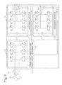
- FIG. 9 shows an example in which the DC/AC converter 10 is constructed from a plurality of inverters 10 - 1 , 10 - 2 , . . . in order to drive a plurality of motors.
- the current sensor 22 and the ground-fault/phase-to-phase short-circuit determining unit 30 for making the ground-fault/phase-to-phase short circuit determination are provided on the AC/DC converter 18 side, the increase in cost is less than would be if an extra current sensor was added to each inverter.
Landscapes
- Engineering & Computer Science (AREA)
- Power Engineering (AREA)
- Control Of Ac Motors In General (AREA)
- Inverter Devices (AREA)
- Testing Of Short-Circuits, Discontinuities, Leakage, Or Incorrect Line Connections (AREA)
Abstract
Description
I R +I S +I T=0 (1)
I R +I S +I T≠0 (2)
Claims (7)
Applications Claiming Priority (2)
| Application Number | Priority Date | Filing Date | Title |
|---|---|---|---|
| JP2010-083257 | 2010-03-31 | ||
| JP2010083257A JP4805396B2 (en) | 2010-03-31 | 2010-03-31 | Motor drive device |
Publications (2)
| Publication Number | Publication Date |
|---|---|
| US20110241590A1 US20110241590A1 (en) | 2011-10-06 |
| US8649130B2 true US8649130B2 (en) | 2014-02-11 |
Family
ID=44650283
Family Applications (1)
| Application Number | Title | Priority Date | Filing Date |
|---|---|---|---|
| US13/025,210 Active 2031-12-02 US8649130B2 (en) | 2010-03-31 | 2011-02-11 | Motor driving apparatus having fault diagnostic function |
Country Status (4)
| Country | Link |
|---|---|
| US (1) | US8649130B2 (en) |
| JP (1) | JP4805396B2 (en) |
| CN (1) | CN102208896A (en) |
| DE (1) | DE102011012386A1 (en) |
Cited By (3)
| Publication number | Priority date | Publication date | Assignee | Title |
|---|---|---|---|---|
| RU2634741C1 (en) * | 2014-05-07 | 2017-11-03 | Чайна Юниверсити Оф Майнинг Энд Текнолоджи | Method for diagnosing malfunction in power converter of switched reluctance motor by method of phase current integration |
| US10585134B2 (en) | 2015-10-05 | 2020-03-10 | General Electric Company | Method and system for locating ground faults in a network of drives |
| US20220247340A1 (en) * | 2019-07-25 | 2022-08-04 | Cummins Inc. | Fault tolerant operations of a six-phase machine |
Families Citing this family (49)
| Publication number | Priority date | Publication date | Assignee | Title |
|---|---|---|---|---|
| US9606163B2 (en) * | 2012-04-09 | 2017-03-28 | Toshiba Mitsubishi-Electric Industrial Systems Corporation | Ground fault detecting circuit and power converting device including the same |
| US9160161B2 (en) | 2012-05-04 | 2015-10-13 | Eaton Corporation | System and method for ground fault detection and protection in adjustable speed drives |
| US10232332B2 (en) | 2012-11-16 | 2019-03-19 | U.S. Well Services, Inc. | Independent control of auger and hopper assembly in electric blender system |
| US9745840B2 (en) | 2012-11-16 | 2017-08-29 | Us Well Services Llc | Electric powered pump down |
| US10407990B2 (en) | 2012-11-16 | 2019-09-10 | U.S. Well Services, LLC | Slide out pump stand for hydraulic fracturing equipment |
| US9410410B2 (en) | 2012-11-16 | 2016-08-09 | Us Well Services Llc | System for pumping hydraulic fracturing fluid using electric pumps |
| US9995218B2 (en) | 2012-11-16 | 2018-06-12 | U.S. Well Services, LLC | Turbine chilling for oil field power generation |
| US9893500B2 (en) | 2012-11-16 | 2018-02-13 | U.S. Well Services, LLC | Switchgear load sharing for oil field equipment |
| US11449018B2 (en) | 2012-11-16 | 2022-09-20 | U.S. Well Services, LLC | System and method for parallel power and blackout protection for electric powered hydraulic fracturing |
| US11476781B2 (en) | 2012-11-16 | 2022-10-18 | U.S. Well Services, LLC | Wireline power supply during electric powered fracturing operations |
| DE102012024728A1 (en) * | 2012-12-18 | 2014-07-03 | Ellenberger & Poensgen Gmbh | Method and device for monitoring an electrical system for a return current |
| CA2908276C (en) | 2014-10-14 | 2022-11-01 | Us Well Services Llc | Parallel power and blackout protection for electric hydraulic fracturing |
| JP6470067B2 (en) * | 2015-02-23 | 2019-02-13 | 東芝シュネデール・インバータ株式会社 | Inverter device and program for inverter device |
| EP3107169A1 (en) * | 2015-06-19 | 2016-12-21 | Schneider Electric Industries SAS | Method of operating a protection device, associated computer program product, protection device and electrical installation |
| JP6365502B2 (en) * | 2015-10-21 | 2018-08-01 | トヨタ自動車株式会社 | Hybrid vehicle |
| US12078110B2 (en) | 2015-11-20 | 2024-09-03 | Us Well Services, Llc | System for gas compression on electric hydraulic fracturing fleets |
| CN105811371B (en) * | 2016-03-14 | 2018-12-25 | 珠海格力电器股份有限公司 | Direct current motor control system fault diagnosis method and device |
| US11181107B2 (en) | 2016-12-02 | 2021-11-23 | U.S. Well Services, LLC | Constant voltage power distribution system for use with an electric hydraulic fracturing system |
| GB2572930B (en) | 2017-02-28 | 2022-03-09 | Illinois Tool Works | Mixing machine system |
| GB2573247B (en) * | 2017-02-28 | 2022-04-20 | Illinois Tool Works | Mixing machine with VFD based diagnostics |
| US10648311B2 (en) | 2017-12-05 | 2020-05-12 | U.S. Well Services, LLC | High horsepower pumping configuration for an electric hydraulic fracturing system |
| AR113611A1 (en) | 2017-12-05 | 2020-05-20 | U S Well Services Inc | MULTIPLE PLUNGER PUMPS AND ASSOCIATED DRIVE SYSTEMS |
| GB2583237B (en) | 2017-12-21 | 2022-06-15 | Illinois Tool Works | Mixing machine |
| CN108667352B (en) * | 2018-04-03 | 2019-05-07 | 西安科技大学 | Two-phase short-circuit fault location and fault-tolerant operation control method of brushless DC motor |
| WO2019241783A1 (en) | 2018-06-15 | 2019-12-19 | U.S. Well Services, Inc. | Integrated mobile power unit for hydraulic fracturing |
| JP6985994B2 (en) * | 2018-07-31 | 2021-12-22 | 株式会社日立産機システム | Power converter and ground fault location diagnosis method |
| US10648270B2 (en) | 2018-09-14 | 2020-05-12 | U.S. Well Services, LLC | Riser assist for wellsites |
| WO2020081313A1 (en) | 2018-10-09 | 2020-04-23 | U.S. Well Services, LLC | Electric powered hydraulic fracturing pump system with single electric powered multi-plunger pump fracturing trailers, filtration units, and slide out platform |
| US10738580B1 (en) | 2019-02-14 | 2020-08-11 | Service Alliance—Houston LLC | Electric driven hydraulic fracking system |
| US10753153B1 (en) | 2019-02-14 | 2020-08-25 | National Service Alliance—Houston LLC | Variable frequency drive configuration for electric driven hydraulic fracking system |
| CA3072788C (en) | 2019-02-14 | 2024-02-27 | National Service Alliance - Houston Llc | Parameter monitoring and control for an electric driven hydraulic fracking system |
| US10988998B2 (en) | 2019-02-14 | 2021-04-27 | National Service Alliance—Houston LLC | Electric driven hydraulic fracking operation |
| US10794165B2 (en) | 2019-02-14 | 2020-10-06 | National Service Alliance—Houston LLC | Power distribution trailer for an electric driven hydraulic fracking system |
| US11578577B2 (en) | 2019-03-20 | 2023-02-14 | U.S. Well Services, LLC | Oversized switchgear trailer for electric hydraulic fracturing |
| CN109921384A (en) * | 2019-03-21 | 2019-06-21 | 惠州市蓝微电子有限公司 | A kind of brushless electric machine starting short-circuit detecting circuit and detection method |
| US11728709B2 (en) | 2019-05-13 | 2023-08-15 | U.S. Well Services, LLC | Encoderless vector control for VFD in hydraulic fracturing applications |
| CA3143050A1 (en) | 2019-06-10 | 2020-12-17 | U.S. Well Services, LLC | Integrated fuel gas heater for mobile fuel conditioning equipment |
| US11108234B2 (en) | 2019-08-27 | 2021-08-31 | Halliburton Energy Services, Inc. | Grid power for hydrocarbon service applications |
| US11459863B2 (en) | 2019-10-03 | 2022-10-04 | U.S. Well Services, LLC | Electric powered hydraulic fracturing pump system with single electric powered multi-plunger fracturing pump |
| DE102019217747A1 (en) * | 2019-11-18 | 2021-05-20 | Rolls-Royce Deutschland Ltd & Co Kg | Detecting an inverter short circuit between two phases |
| DE102019217748A1 (en) * | 2019-11-18 | 2021-05-20 | Rolls-Royce Deutschland Ltd & Co Kg | Detecting a phase-to-ground inverter short circuit |
| JP7328132B2 (en) | 2019-12-03 | 2023-08-16 | ファナック株式会社 | Motor drive device for determining cause of DC link voltage fluctuation |
| CA3161918A1 (en) | 2019-12-27 | 2021-07-01 | Alexander CHRISTINZIO | Systems and methods for fluid end health monitoring |
| US11009162B1 (en) | 2019-12-27 | 2021-05-18 | U.S. Well Services, LLC | System and method for integrated flow supply line |
| CN111244898A (en) * | 2019-12-30 | 2020-06-05 | 扬州曙光光电自控有限责任公司 | A protection circuit and method for phase-to-phase short-circuit at the output end of an AC servo drive |
| US11885206B2 (en) | 2019-12-30 | 2024-01-30 | U.S. Well Services, LLC | Electric motor driven transportation mechanisms for fracturing blenders |
| US11492886B2 (en) | 2019-12-31 | 2022-11-08 | U.S. Wells Services, LLC | Self-regulating FRAC pump suction stabilizer/dampener |
| CN114325382B (en) * | 2021-12-17 | 2023-08-22 | 珠海格力电器股份有限公司 | Method and system for detecting open-phase fault of three-phase alternating current motor and electric equipment |
| US12009671B2 (en) * | 2022-02-17 | 2024-06-11 | The Boeing Company | System and method for ground fault monitoring in an aircraft |
Citations (16)
| Publication number | Priority date | Publication date | Assignee | Title |
|---|---|---|---|---|
| US4380785A (en) * | 1980-03-31 | 1983-04-19 | Merlin Gerin | Solid state trip unit for an electrical circuit breaker |
| JPH0410536A (en) | 1990-04-27 | 1992-01-14 | Hitachi Cable Ltd | Separation method of epitaxial layer and substrate |
| JPH05168290A (en) * | 1991-12-12 | 1993-07-02 | Tokyo Electric Power Co Inc:The | SELVIUS device |
| DE4242560A1 (en) | 1992-01-23 | 1993-07-29 | Mitsubishi Electric Corp | Overcurrent protection circuit, esp for motor drive circuit semiconductor elements - contains switching device, protection diode and detectors for currents in diode and in switching element |
| JPH06233450A (en) * | 1993-02-04 | 1994-08-19 | Nippondenso Co Ltd | Fault detecting device for motor drive circuit |
| JPH07239359A (en) | 1994-02-25 | 1995-09-12 | Mitsubishi Electric Corp | Inverter device and operating method thereof |
| US5896257A (en) * | 1997-10-17 | 1999-04-20 | Allen-Bradley Company, Llc | Two sensor for over-current protection and current sensing configuration motor control |
| JP3108964B2 (en) | 1991-11-26 | 2000-11-13 | 株式会社日立製作所 | Motor control device |
| US6320731B1 (en) * | 2000-05-24 | 2001-11-20 | Electric Boat Corporation | Fault tolerant motor drive arrangement with independent phase connections and monitoring system |
| US20030030954A1 (en) * | 2001-02-01 | 2003-02-13 | Bax Ronald A. | Current fault detector and circuit interrupter and packaging thereof |
| JP2004056889A (en) | 2002-07-18 | 2004-02-19 | Nissan Motor Co Ltd | Current sensor diagnostic device |
| JP2004072997A (en) | 2002-08-02 | 2004-03-04 | Dr Johannes Heidenhain Gmbh | Method for detecting abnormality of drive device |
| JP2006020483A (en) | 2004-06-30 | 2006-01-19 | Taiwa Denki Kogyo Kk | Detection device of insulation degradation for inverter device |
| JP2006230194A (en) * | 2006-04-19 | 2006-08-31 | Sanyo Electric Co Ltd | Refrigeration system |
| US20090009920A1 (en) * | 2007-07-04 | 2009-01-08 | Toyota Jidosha Kabushiki Kaisha | Abnormality detecting device of electric power converting device and abnormality detecting method |
| US20090086396A1 (en) * | 2001-02-01 | 2009-04-02 | Hydro-Aire, Inc., A Subsidiary Of Crane Co. | Current fault detector and circuit interrupter and packaging thereof |
Family Cites Families (1)
| Publication number | Priority date | Publication date | Assignee | Title |
|---|---|---|---|---|
| JPS6385380A (en) * | 1986-09-29 | 1988-04-15 | Toshiba Corp | Method for detecting trouble of motor |
-
2010
- 2010-03-31 JP JP2010083257A patent/JP4805396B2/en not_active Expired - Fee Related
-
2011
- 2011-02-11 US US13/025,210 patent/US8649130B2/en active Active
- 2011-02-23 CN CN2011100474038A patent/CN102208896A/en active Pending
- 2011-02-25 DE DE102011012386A patent/DE102011012386A1/en not_active Withdrawn
Patent Citations (19)
| Publication number | Priority date | Publication date | Assignee | Title |
|---|---|---|---|---|
| US4380785A (en) * | 1980-03-31 | 1983-04-19 | Merlin Gerin | Solid state trip unit for an electrical circuit breaker |
| JPH0410536A (en) | 1990-04-27 | 1992-01-14 | Hitachi Cable Ltd | Separation method of epitaxial layer and substrate |
| JP3108964B2 (en) | 1991-11-26 | 2000-11-13 | 株式会社日立製作所 | Motor control device |
| JPH05168290A (en) * | 1991-12-12 | 1993-07-02 | Tokyo Electric Power Co Inc:The | SELVIUS device |
| DE4242560A1 (en) | 1992-01-23 | 1993-07-29 | Mitsubishi Electric Corp | Overcurrent protection circuit, esp for motor drive circuit semiconductor elements - contains switching device, protection diode and detectors for currents in diode and in switching element |
| US5375028A (en) | 1992-01-23 | 1994-12-20 | Mitsubishi Denki Kabushiki Kaisha | Overcurrent protective device and device for detecting overcurrent |
| JPH06233450A (en) * | 1993-02-04 | 1994-08-19 | Nippondenso Co Ltd | Fault detecting device for motor drive circuit |
| JPH07239359A (en) | 1994-02-25 | 1995-09-12 | Mitsubishi Electric Corp | Inverter device and operating method thereof |
| US5896257A (en) * | 1997-10-17 | 1999-04-20 | Allen-Bradley Company, Llc | Two sensor for over-current protection and current sensing configuration motor control |
| US6320731B1 (en) * | 2000-05-24 | 2001-11-20 | Electric Boat Corporation | Fault tolerant motor drive arrangement with independent phase connections and monitoring system |
| US20030030954A1 (en) * | 2001-02-01 | 2003-02-13 | Bax Ronald A. | Current fault detector and circuit interrupter and packaging thereof |
| US7016171B2 (en) * | 2001-02-01 | 2006-03-21 | Hydro-Aire, Inc. | Current fault detector and circuit interrupter and packaging thereof |
| US20090086396A1 (en) * | 2001-02-01 | 2009-04-02 | Hydro-Aire, Inc., A Subsidiary Of Crane Co. | Current fault detector and circuit interrupter and packaging thereof |
| JP2004056889A (en) | 2002-07-18 | 2004-02-19 | Nissan Motor Co Ltd | Current sensor diagnostic device |
| JP2004072997A (en) | 2002-08-02 | 2004-03-04 | Dr Johannes Heidenhain Gmbh | Method for detecting abnormality of drive device |
| JP2006020483A (en) | 2004-06-30 | 2006-01-19 | Taiwa Denki Kogyo Kk | Detection device of insulation degradation for inverter device |
| JP2006230194A (en) * | 2006-04-19 | 2006-08-31 | Sanyo Electric Co Ltd | Refrigeration system |
| US20090009920A1 (en) * | 2007-07-04 | 2009-01-08 | Toyota Jidosha Kabushiki Kaisha | Abnormality detecting device of electric power converting device and abnormality detecting method |
| US7733616B2 (en) * | 2007-07-04 | 2010-06-08 | Toyota Jidosha Kabushiki Kaisha | Abnormality detecting device of electric power converting device and abnormality detecting method |
Non-Patent Citations (1)
| Title |
|---|
| Chinese Office Action issued in 2011100474038 dated Apr. 19, 2013. |
Cited By (4)
| Publication number | Priority date | Publication date | Assignee | Title |
|---|---|---|---|---|
| RU2634741C1 (en) * | 2014-05-07 | 2017-11-03 | Чайна Юниверсити Оф Майнинг Энд Текнолоджи | Method for diagnosing malfunction in power converter of switched reluctance motor by method of phase current integration |
| US10585134B2 (en) | 2015-10-05 | 2020-03-10 | General Electric Company | Method and system for locating ground faults in a network of drives |
| US20220247340A1 (en) * | 2019-07-25 | 2022-08-04 | Cummins Inc. | Fault tolerant operations of a six-phase machine |
| US11777437B2 (en) * | 2019-07-25 | 2023-10-03 | Cummins Inc. | Fault tolerant operations of a six-phase machine |
Also Published As
| Publication number | Publication date |
|---|---|
| US20110241590A1 (en) | 2011-10-06 |
| JP4805396B2 (en) | 2011-11-02 |
| DE102011012386A1 (en) | 2011-10-06 |
| JP2011217518A (en) | 2011-10-27 |
| CN102208896A (en) | 2011-10-05 |
Similar Documents
| Publication | Publication Date | Title |
|---|---|---|
| US8649130B2 (en) | Motor driving apparatus having fault diagnostic function | |
| EP2769462B1 (en) | Method and system for detecting a failed rectifier in an ac/dc converter | |
| US8355226B2 (en) | Ground fault sensing device | |
| US8593150B2 (en) | Method and apparatus for detecting a location of ground faults in a motor/motor drive combination | |
| US20160154046A1 (en) | System and method for detecting ground fault in a dc system | |
| CN104364989B (en) | System and method for high resistance grounding fault detect in a power distribution system and protection | |
| US8643383B2 (en) | Drive failure protection | |
| US9007790B2 (en) | Frequency converter and method for identifying and blocking a fault current in a frequency converter | |
| JP5530769B2 (en) | DC circuit leakage detection device | |
| JP5689497B2 (en) | Motor drive device having DC link unit abnormality detection function | |
| EP2857850B1 (en) | HRG ground fault detector and method | |
| US20120086458A1 (en) | System for detection of a ground fault in a high resistance ground network | |
| US11509254B2 (en) | Method for detecting a motor phase fault of a motor arrangement and drive circuit for driving an electronically commutated motor | |
| KR102274269B1 (en) | Detecting shorted diodes | |
| JPH05328739A (en) | Power conversion equipment and detection ground fault method thereof | |
| US9488698B2 (en) | System and method for detecting diode failures | |
| JP6344558B2 (en) | Fault detection device for semiconductor power converter | |
| CN109980899B (en) | Current detection circuit, frequency converter and current detection method | |
| JP5272678B2 (en) | Overexcitation detection device | |
| KR20180097301A (en) | Apparatus for detecting abnormality in current sensor of inverter | |
| JP3724913B2 (en) | Rotor field current measuring device for brushless synchronous machine | |
| US12399231B2 (en) | Fault detection method and system therefor | |
| JP2003164162A (en) | Inverter phase open phase detection method and power converter | |
| JP2010246279A (en) | Control device for three-phase AC electric vehicle and control method for three-phase AC electric vehicle |
Legal Events
| Date | Code | Title | Description |
|---|---|---|---|
| AS | Assignment |
Owner name: FANUC CORPORATION, JAPAN Free format text: ASSIGNMENT OF ASSIGNORS INTEREST;ASSIGNORS:HORIKOSHI, SHINICHI;HARADA, TAKASHI;SHIROUZU, MASATOMO;AND OTHERS;REEL/FRAME:025792/0065 Effective date: 20110121 |
|
| STCF | Information on status: patent grant |
Free format text: PATENTED CASE |
|
| FPAY | Fee payment |
Year of fee payment: 4 |
|
| MAFP | Maintenance fee payment |
Free format text: PAYMENT OF MAINTENANCE FEE, 8TH YEAR, LARGE ENTITY (ORIGINAL EVENT CODE: M1552); ENTITY STATUS OF PATENT OWNER: LARGE ENTITY Year of fee payment: 8 |
|
| FEPP | Fee payment procedure |
Free format text: MAINTENANCE FEE REMINDER MAILED (ORIGINAL EVENT CODE: REM.); ENTITY STATUS OF PATENT OWNER: LARGE ENTITY |