US8643618B2 - Electromagnetic-type touch input device, and touch display device incorporating the same - Google Patents

Electromagnetic-type touch input device, and touch display device incorporating the same Download PDF

Info

Publication number
US8643618B2
US8643618B2 US13/230,025 US201113230025A US8643618B2 US 8643618 B2 US8643618 B2 US 8643618B2 US 201113230025 A US201113230025 A US 201113230025A US 8643618 B2 US8643618 B2 US 8643618B2
Authority
US
United States
Prior art keywords
sensing output
sensing
display area
electronic stylus
output
Prior art date
Legal status (The legal status is an assumption and is not a legal conclusion. Google has not performed a legal analysis and makes no representation as to the accuracy of the status listed.)
Expired - Fee Related, expires
Application number
US13/230,025
Other versions
US20120062514A1 (en
Inventor
Joe Yu
Current Assignee (The listed assignees may be inaccurate. Google has not performed a legal analysis and makes no representation or warranty as to the accuracy of the list.)
UC Logic Technology Corp
Original Assignee
UC Logic Technology Corp
Priority date (The priority date is an assumption and is not a legal conclusion. Google has not performed a legal analysis and makes no representation as to the accuracy of the date listed.)
Filing date
Publication date
Application filed by UC Logic Technology Corp filed Critical UC Logic Technology Corp
Assigned to UC-LOGIC TECHNOLOGY CORP. reassignment UC-LOGIC TECHNOLOGY CORP. ASSIGNMENT OF ASSIGNORS INTEREST (SEE DOCUMENT FOR DETAILS). Assignors: YU, JOE
Publication of US20120062514A1 publication Critical patent/US20120062514A1/en
Application granted granted Critical
Publication of US8643618B2 publication Critical patent/US8643618B2/en
Expired - Fee Related legal-status Critical Current
Adjusted expiration legal-status Critical

Links

Images

Classifications

    • GPHYSICS
    • G06COMPUTING OR CALCULATING; COUNTING
    • G06FELECTRIC DIGITAL DATA PROCESSING
    • G06F3/00Input arrangements for transferring data to be processed into a form capable of being handled by the computer; Output arrangements for transferring data from processing unit to output unit, e.g. interface arrangements
    • G06F3/01Input arrangements or combined input and output arrangements for interaction between user and computer
    • G06F3/03Arrangements for converting the position or the displacement of a member into a coded form
    • G06F3/041Digitisers, e.g. for touch screens or touch pads, characterised by the transducing means
    • G06F3/046Digitisers, e.g. for touch screens or touch pads, characterised by the transducing means by electromagnetic means
    • GPHYSICS
    • G06COMPUTING OR CALCULATING; COUNTING
    • G06FELECTRIC DIGITAL DATA PROCESSING
    • G06F3/00Input arrangements for transferring data to be processed into a form capable of being handled by the computer; Output arrangements for transferring data from processing unit to output unit, e.g. interface arrangements
    • G06F3/01Input arrangements or combined input and output arrangements for interaction between user and computer
    • G06F3/03Arrangements for converting the position or the displacement of a member into a coded form
    • G06F3/041Digitisers, e.g. for touch screens or touch pads, characterised by the transducing means
    • G06F3/0416Control or interface arrangements specially adapted for digitisers
    • G06F3/0418Control or interface arrangements specially adapted for digitisers for error correction or compensation, e.g. based on parallax, calibration or alignment
    • G06F3/04182Filtering of noise external to the device and not generated by digitiser components
    • GPHYSICS
    • G09EDUCATION; CRYPTOGRAPHY; DISPLAY; ADVERTISING; SEALS
    • G09GARRANGEMENTS OR CIRCUITS FOR CONTROL OF INDICATING DEVICES USING STATIC MEANS TO PRESENT VARIABLE INFORMATION
    • G09G3/00Control arrangements or circuits, of interest only in connection with visual indicators other than cathode-ray tubes
    • G09G3/20Control arrangements or circuits, of interest only in connection with visual indicators other than cathode-ray tubes for presentation of an assembly of a number of characters, e.g. a page, by composing the assembly by combination of individual elements arranged in a matrix no fixed position being assigned to or needed to be assigned to the individual characters or partial characters
    • G09G3/34Control arrangements or circuits, of interest only in connection with visual indicators other than cathode-ray tubes for presentation of an assembly of a number of characters, e.g. a page, by composing the assembly by combination of individual elements arranged in a matrix no fixed position being assigned to or needed to be assigned to the individual characters or partial characters by control of light from an independent source
    • G09G3/36Control arrangements or circuits, of interest only in connection with visual indicators other than cathode-ray tubes for presentation of an assembly of a number of characters, e.g. a page, by composing the assembly by combination of individual elements arranged in a matrix no fixed position being assigned to or needed to be assigned to the individual characters or partial characters by control of light from an independent source using liquid crystals
    • GPHYSICS
    • G09EDUCATION; CRYPTOGRAPHY; DISPLAY; ADVERTISING; SEALS
    • G09GARRANGEMENTS OR CIRCUITS FOR CONTROL OF INDICATING DEVICES USING STATIC MEANS TO PRESENT VARIABLE INFORMATION
    • G09G2330/00Aspects of power supply; Aspects of display protection and defect management
    • G09G2330/06Handling electromagnetic interferences [EMI], covering emitted as well as received electromagnetic radiation

Definitions

  • the invention relates to a touch input device, and more particularly to an electromagnetic-type touch input device, and a touch display device incorporating the same.
  • a conventional touch display device 9 is shown to use with an electronic stylus 8 capable of radiating an electromagnetic wave signal.
  • the conventional touch display device 9 includes a liquid crystal display (LCD) module 91 , an electromagnetic-type touch panel 92 (not shown in FIG. 1 ) disposed under the LCD module 91 , and a frame 94 for holding and receiving the LCD module 91 and the electromagnetic-type touch panel 92 therein.
  • the LCD module 91 has a rectangular display area 911 exposed from the frame 94 .
  • the electromagnetic-type touch panel 92 includes a sensor board 921 , an X-axis multiplexer 922 , a Y-axis multiplexer 923 , and a controller 924 .
  • the sensor board 921 includes an X-axis antenna array consisting of a plurality of X-axis antenna coils and coupled to the X-axis multiplexer 922 , and a Y-axis antenna array consisting of a plurality of Y-axis antenna coils and coupled to the Y-axis multiplexer 923 .
  • the sensor board 921 senses the electromagnetic wave signal from the electronic stylus 8 upon a touching by the electronic stylus 8 on the display area 911 so as to output respectively an X-axis sensing signal and a Y-axis sensing signal to the X-axis and Y-axis multiplexers 922 , 923 .
  • the controller 924 is connected electrically to the X-axis and Y-axis multiplexers 922 , 923 , and is operable to control the X-axis and Y-axis multiplexers 922 , 923 to output the X-axis and Y-axis sensing signals to the controller 924 such that the controller 924 generates an input signal corresponding to a location of a touch point of the electronic stylus 8 .
  • an object of the present invention is to provide an electromagnetic-type touch input device, and a touch display device incorporating the same that can overcome the aforesaid drawbacks of the prior art.
  • a touch display device adapted for use with an electronic stylus capable of radiating an electromagnetic wave signal.
  • the touch display device comprises:
  • LCD liquid crystal display
  • an electromagnetic-type touch input device including
  • an electromagnetic-type touch input device that is adapted to be integrated with a liquid crystal display (LCD) module and that is adapted for use with an electronic stylus capable of radiating an electromagnetic wave signal.
  • the LCD module has a top surface configured with a central display area and a peripheral non-display area surrounding the central display area.
  • the electromagnetic-type touch input device comprises:
  • a main sensor board adapted to be disposed under the LCD module for sensing the electromagnetic wave signal from the electronic stylus upon a touching by the electronic stylus so as to generate a first sensing output corresponding to a touch point of the electronic stylus;
  • an auxiliary periphery sensor adapted to be disposed on the top surface of the LCD module, and including a plurality of X-axis antenna coils and a plurality of Y-axis antenna coils disposed above the peripheral non-display area of the top surface of the LCD module for sensing the electromagnetic wave signal from the electronic stylus upon the touching by the electronic stylus so as to generate a second sensing output corresponding to the touch point of the electronic stylus;
  • control unit connected electrically to the main sensor board and the auxiliary periphery sensor for receiving the first and second sensing outputs therefrom, the control unit being operable to output an input signal associated with a two-dimensional coordinate and corresponding to a location of the touch point of the electronic stylus based on the first and second sensing outputs.
  • FIG. 1 is a perspective view showing a conventional touch display device
  • FIG. 2 is a schematic electrical circuit block diagram illustrating an electromagnetic-type touch panel of the conventional touch display device
  • FIG. 3 is a schematic circuit block diagram illustrating the first preferred embodiment of a touch display device according to the present invention
  • FIG. 4 is an exploded perspective view showing the first preferred embodiment
  • FIG. 5 is a schematic electrical circuit diagram illustrating an auxiliary periphery sensor of the first preferred embodiment.
  • FIG. 6 is an exploded perspective view showing the second preferred embodiment of a touch display device according to the present invention.
  • the first preferred embodiment of a touch display device is shown to include an LCD module 1 , and an electromagnetic-type touch input device that is adapted for use with an electronic stylus 6 and that includes a main sensor board 2 , an auxiliary periphery sensor 3 and a control unit 4 .
  • the electronic stylus 6 is capable of radiating an electromagnetic wave signal.
  • the LCD module 1 has a rectangular top surface 11 that is configured with a rectangular central display area 111 , and a peripheral non-display area 112 surrounding the central display area 111 .
  • the main sensor board 2 is disposed under the LCD module 1 for sensing the electromagnetic wave signal from the electronic stylus 6 upon a touching by the electronic stylus 6 with an operating surface of the touch display device (not shown) so as to generate a first sensing output corresponding to a touch point of the electronic stylus 6 .
  • the main sensor board 2 has the same configuration as that of the sensor board 921 of FIG. 2 . Since the feature of this invention does not reside in the configuration of the main sensor board 2 , which is known to those skilled in the art, details of the same are omitted herein for the sake of brevity.
  • the auxiliary periphery sensor 3 is in the form of a looped circuit board having a size corresponding to that of the peripheral non-display area 112 of the top surface 11 of the LCD module 1 and attached to the peripheral non-display area 112 of the top surface 11 of the LCD module 1 .
  • the auxiliary periphery sensor 3 includes a plurality of X-axis antenna coils 31 and a plurality of Y-axis antenna coils 32 , as shown in FIG. 5 , formed into the looped circuit board for sensing the electromagnetic wave signal from the electronic stylus 6 upon the touching by the electronic stylus 6 with the operating surface of the touch display device so as to generate a second sensing output corresponding to the touch point of the electronic stylus 6 .
  • the looped circuit board can be a flexible printed circuit board adhered to the peripheral non-display area 112 of the top surface 11 of the LCD module 1 .
  • the control unit 4 is disposed under the main sensor board 2 , and is connected electrically to the main sensor board 2 and the auxiliary periphery sensor 3 for receiving the first and second sensing output therefrom.
  • the control unit 4 is operable to output an input signal associated with a two-dimensional coordinate and corresponding to a location of the touch point of the electronic stylus 6 based on the first and second sensing outputs from the main sensor board 2 and the auxiliary periphery sensor 3 .
  • control unit 4 includes a first multiplexer unit 41 , an auxiliary control module 43 , and a main controller 42 .
  • the first multiplexer unit 41 includes an-X-axis multiplexer and a Y-axis multiplexer (not shown) connected electrically to the main sensor board 2 for receiving the first sensing output from the main sensor board 2 .
  • the first multiplexer unit 41 is operable to output the first sensing output.
  • the auxiliary control module 43 includes a second multiplexer unit 431 , a bandpass filter unit 432 and a processor 433 .
  • the second multiplexer unit 431 is connected electrically to the auxiliary periphery sensor 3 for receiving the second sensing output from the auxiliary periphery sensor 3 .
  • the second multiplexer 431 is operable to output the second sensing output.
  • the bandpass filter unit 432 is connected electrically to the second multiplexer unit 431 , filters the second sensing output from the second multiplexer unit 431 , and generates a filtered sensing output.
  • the processor 433 is connected electrically to the bandpass filter unit 432 and the second multiplexer unit 431 .
  • the processor 433 is connected electrically to the bandpass filter unit 432 and the second multiplexer unit 431 .
  • the processor 433 controls the second multiplexer unit 431 to output the second sensing output to the bandpass filter unit 432 , and processes the filtered sensing output from the bandpass filter unit 432 so as to output a processed sensing output corresponding to the second sensing output.
  • the main controller 42 is connected electrically to the first multiplexer unit 41 and the processor 433 of the auxiliary control module 43 , and controls the first multiplexer unit 41 so that the first multiplexer unit 41 outputs the first sensing output to the main controller 42 .
  • the main controller 42 receives the first sensing output from the first multiplexer unit 41 and the processed sensing output from the processor 433 of the auxiliary control module 43 , and generates the input signal based on at least one of the first sensing output from the first multiplexer unit 41 and the processed sensing output from the processor 433 of the auxiliary control module 43 .
  • the main controller 42 when the location of the touch point of the electronic stylus 6 is on the central display area 111 of the top surface 11 of the LCD module 1 , the main controller 42 generates the input signal based on the first sensing output from the first multiplexer unit 41 .
  • the main controller 42 When the location of the touch point of the electronic stylus 6 is on a boundary area 113 between the central display area 111 and the peripheral non-display area 112 of the top surface 11 of the LCD module 1 , the main controller 42 generates the input signal based on the first sensing output from the first multiplexer unit 41 and the processed sensing output from the processor 433 of the auxiliary control module 43 .
  • the main controller 42 When the location of the touch point of the electronic stylus 6 is on the peripheral non-display area 112 of the top surface 11 of the LCD module 1 , the main controller 42 generates the input signal based on the processed sensing output from the processor 433 of the auxiliary control module 43 .
  • the touch display device of the present invention can generate an input signal corresponding to a location of a touch point of the electronic stylus 6 on the boundary area 113 between the central display area 111 and the peripheral non-display area 112 of the top surface 11 of the LCD module 1 without complicated calibration operation.
  • the touch display device can still generate an input signal corresponding to a location of a touch point of the electronic stylus 6 on the peripheral non-display area 112 of the top surface 111 of the LCD module 1 . Therefore, the touch display device of the present invention has a relatively large operating area as compared to the prior art.
  • FIG. 6 illustrates the second preferred embodiment of a touch display device according to this invention, which is a modification of the first preferred embodiment.
  • the auxiliary periphery sensor 3 ′ includes a transparent plate 33 attached to the top surface 11 of the LCD module 1 .
  • the transparent plate 33 has a bottom surface 331 that has a periphery area corresponding to the peripheral non-display area 112 of the top surface 11 of the LCD module 1 and provided with the X-axis and Y-axis antenna coils 31 , 32 thereon such that the X-axis and Y-axis antenna coils 31 , 32 are disposed between the LCD module 1 and the transparent plate 33 .
  • the transparent plate 33 can serve as a cover lens of the touch display device.

Landscapes

  • Engineering & Computer Science (AREA)
  • Theoretical Computer Science (AREA)
  • Physics & Mathematics (AREA)
  • General Engineering & Computer Science (AREA)
  • General Physics & Mathematics (AREA)
  • Human Computer Interaction (AREA)
  • Chemical & Material Sciences (AREA)
  • Crystallography & Structural Chemistry (AREA)
  • Computer Hardware Design (AREA)
  • Electromagnetism (AREA)
  • Position Input By Displaying (AREA)

Abstract

An electromagnetic-type touch input device of a touch display device includes: a main sensor board disposed under a liquid crystal display (LCD) module for sensing an electromagnetic wave signal from an electronic stylus upon a touching by the electronic so as to generate a first sensing output; an auxiliary periphery sensor disposed on a top surface of the LCD module configured with a peripheral non-display area surrounding a central display area, and including X-axis and Y-axis antenna coils disposed above said peripheral non-display area of the LCD module for sensing the electromagnetic wave signal from the electronic stylus upon the touching by the electronic stylus so as to generate a second sensing output; and a control unit outputting an input signal associated with a two-dimensional coordinate and corresponding to a location of a touch point of the electronic stylus based on the first and second sensing outputs.

Description

CROSS-REFERENCE TO RELATED APPLICATION
This application claims priority to Taiwanese Application No. 099131196, filed on Sep. 15, 2010.
BACKGROUND OF THE INVENTION
1. Field of the Invention
The invention relates to a touch input device, and more particularly to an electromagnetic-type touch input device, and a touch display device incorporating the same.
2. Description of the Related Art
Referring to FIGS. 1 and 2, a conventional touch display device 9 is shown to use with an electronic stylus 8 capable of radiating an electromagnetic wave signal. The conventional touch display device 9 includes a liquid crystal display (LCD) module 91, an electromagnetic-type touch panel 92 (not shown in FIG. 1) disposed under the LCD module 91, and a frame 94 for holding and receiving the LCD module 91 and the electromagnetic-type touch panel 92 therein. The LCD module 91 has a rectangular display area 911 exposed from the frame 94. As shown in FIG. 2, the electromagnetic-type touch panel 92 includes a sensor board 921, an X-axis multiplexer 922, a Y-axis multiplexer 923, and a controller 924. The sensor board 921 includes an X-axis antenna array consisting of a plurality of X-axis antenna coils and coupled to the X-axis multiplexer 922, and a Y-axis antenna array consisting of a plurality of Y-axis antenna coils and coupled to the Y-axis multiplexer 923. The sensor board 921 senses the electromagnetic wave signal from the electronic stylus 8 upon a touching by the electronic stylus 8 on the display area 911 so as to output respectively an X-axis sensing signal and a Y-axis sensing signal to the X-axis and Y- axis multiplexers 922, 923. The controller 924 is connected electrically to the X-axis and Y- axis multiplexers 922, 923, and is operable to control the X-axis and Y- axis multiplexers 922, 923 to output the X-axis and Y-axis sensing signals to the controller 924 such that the controller 924 generates an input signal corresponding to a location of a touch point of the electronic stylus 8.
In such a conventional touch display device, when the touch point of the electronic stylus 8 is located within a periphery portion of the display area 911, due to external interferences, the sensor board 921 cannot accurately sense the electromagnetic wave signal from the electronic stylus 8. Therefore, complicated calibration for the periphery portion of the display area 911 is required for the touch panel 92. In addition, when the touch point of the electronic stylus 8 is located on a peripheral non-display area 912 of the LCD module 91 surrounding the display area 911 and covered by the frame 94, the touch panel 92 will not generate any input signal, i.e., it is regarded as a non-useful operation. Therefore, improvements may be made to the above techniques.
SUMMARY OF THE INVENTION
Therefore, an object of the present invention is to provide an electromagnetic-type touch input device, and a touch display device incorporating the same that can overcome the aforesaid drawbacks of the prior art.
According to one aspect of the present invention, there is provided a touch display device adapted for use with an electronic stylus capable of radiating an electromagnetic wave signal. The touch display device comprises:
a liquid crystal display (LCD) module having a top surface, the top surface being configured with a central display area, and a peripheral non-display area surrounding the central display area; and
an electromagnetic-type touch input device including
    • a main sensor board disposed under the LCD module for sensing the electromagnetic wave signal from the electronic stylus upon a touching by the electronic stylus so as to generate a first sensing output corresponding to a touch point of the electronic stylus,
    • an auxiliary periphery sensor disposed on the top surface of the LCD module, and including a plurality of X-axis antenna coils and a plurality of Y-axis antenna coils disposed above the peripheral non-display area of the top surface of the LCD module for sensing the electromagnetic wave signal from the electronic stylus upon the touching by the electronic stylus so as to generate a second sensing output corresponding to the touch point of the electronic stylus, and
    • a control unit connected electrically to the main sensor board and the auxiliary periphery sensor for receiving the first and second sensing outputs therefrom, the control unit being operable to output an input signal associated with a two-dimensional coordinate and corresponding to a location of the touch point of the electronic stylus based on the first and second sensing outputs.
According to another aspect of the present invention, there is provided an electromagnetic-type touch input device that is adapted to be integrated with a liquid crystal display (LCD) module and that is adapted for use with an electronic stylus capable of radiating an electromagnetic wave signal. The LCD module has a top surface configured with a central display area and a peripheral non-display area surrounding the central display area. The electromagnetic-type touch input device comprises:
a main sensor board adapted to be disposed under the LCD module for sensing the electromagnetic wave signal from the electronic stylus upon a touching by the electronic stylus so as to generate a first sensing output corresponding to a touch point of the electronic stylus;
an auxiliary periphery sensor adapted to be disposed on the top surface of the LCD module, and including a plurality of X-axis antenna coils and a plurality of Y-axis antenna coils disposed above the peripheral non-display area of the top surface of the LCD module for sensing the electromagnetic wave signal from the electronic stylus upon the touching by the electronic stylus so as to generate a second sensing output corresponding to the touch point of the electronic stylus; and
a control unit connected electrically to the main sensor board and the auxiliary periphery sensor for receiving the first and second sensing outputs therefrom, the control unit being operable to output an input signal associated with a two-dimensional coordinate and corresponding to a location of the touch point of the electronic stylus based on the first and second sensing outputs.
BRIEF DESCRIPTION OF THE DRAWINGS
Other features and advantages of the present invention will become apparent in the following detailed description of the preferred embodiments with reference to the accompanying drawings, of which:
FIG. 1 is a perspective view showing a conventional touch display device;
FIG. 2 is a schematic electrical circuit block diagram illustrating an electromagnetic-type touch panel of the conventional touch display device;
FIG. 3 is a schematic circuit block diagram illustrating the first preferred embodiment of a touch display device according to the present invention;
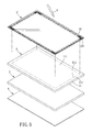
FIG. 4 is an exploded perspective view showing the first preferred embodiment;
FIG. 5 is a schematic electrical circuit diagram illustrating an auxiliary periphery sensor of the first preferred embodiment; and
FIG. 6 is an exploded perspective view showing the second preferred embodiment of a touch display device according to the present invention.
DETAILED DESCRIPTION OF THE PREFERRED EMBODIMENTS
Before the present invention is described in greater detail, it should be noted that like elements are denoted by the same reference numerals throughout the disclosure.
Referring to FIGS. 3 and 4, the first preferred embodiment of a touch display device according to the present invention is shown to include an LCD module 1, and an electromagnetic-type touch input device that is adapted for use with an electronic stylus 6 and that includes a main sensor board 2, an auxiliary periphery sensor 3 and a control unit 4. The electronic stylus 6 is capable of radiating an electromagnetic wave signal.
Referring further to FIG. 4, the LCD module 1 has a rectangular top surface 11 that is configured with a rectangular central display area 111, and a peripheral non-display area 112 surrounding the central display area 111.
The main sensor board 2 is disposed under the LCD module 1 for sensing the electromagnetic wave signal from the electronic stylus 6 upon a touching by the electronic stylus 6 with an operating surface of the touch display device (not shown) so as to generate a first sensing output corresponding to a touch point of the electronic stylus 6. The main sensor board 2 has the same configuration as that of the sensor board 921 of FIG. 2. Since the feature of this invention does not reside in the configuration of the main sensor board 2, which is known to those skilled in the art, details of the same are omitted herein for the sake of brevity.
In this embodiment, the auxiliary periphery sensor 3 is in the form of a looped circuit board having a size corresponding to that of the peripheral non-display area 112 of the top surface 11 of the LCD module 1 and attached to the peripheral non-display area 112 of the top surface 11 of the LCD module 1. The auxiliary periphery sensor 3 includes a plurality of X-axis antenna coils 31 and a plurality of Y-axis antenna coils 32, as shown in FIG. 5, formed into the looped circuit board for sensing the electromagnetic wave signal from the electronic stylus 6 upon the touching by the electronic stylus 6 with the operating surface of the touch display device so as to generate a second sensing output corresponding to the touch point of the electronic stylus 6. In other embodiments, the looped circuit board can be a flexible printed circuit board adhered to the peripheral non-display area 112 of the top surface 11 of the LCD module 1.
The control unit 4 is disposed under the main sensor board 2, and is connected electrically to the main sensor board 2 and the auxiliary periphery sensor 3 for receiving the first and second sensing output therefrom. The control unit 4 is operable to output an input signal associated with a two-dimensional coordinate and corresponding to a location of the touch point of the electronic stylus 6 based on the first and second sensing outputs from the main sensor board 2 and the auxiliary periphery sensor 3.
In this embodiment, the control unit 4 includes a first multiplexer unit 41, an auxiliary control module 43, and a main controller 42.
The first multiplexer unit 41 includes an-X-axis multiplexer and a Y-axis multiplexer (not shown) connected electrically to the main sensor board 2 for receiving the first sensing output from the main sensor board 2. The first multiplexer unit 41 is operable to output the first sensing output.
The auxiliary control module 43 includes a second multiplexer unit 431, a bandpass filter unit 432 and a processor 433. The second multiplexer unit 431 is connected electrically to the auxiliary periphery sensor 3 for receiving the second sensing output from the auxiliary periphery sensor 3. The second multiplexer 431 is operable to output the second sensing output. The bandpass filter unit 432 is connected electrically to the second multiplexer unit 431, filters the second sensing output from the second multiplexer unit 431, and generates a filtered sensing output. The processor 433 is connected electrically to the bandpass filter unit 432 and the second multiplexer unit 431. The processor 433 is connected electrically to the bandpass filter unit 432 and the second multiplexer unit 431. The processor 433 controls the second multiplexer unit 431 to output the second sensing output to the bandpass filter unit 432, and processes the filtered sensing output from the bandpass filter unit 432 so as to output a processed sensing output corresponding to the second sensing output.
The main controller 42 is connected electrically to the first multiplexer unit 41 and the processor 433 of the auxiliary control module 43, and controls the first multiplexer unit 41 so that the first multiplexer unit 41 outputs the first sensing output to the main controller 42. The main controller 42 receives the first sensing output from the first multiplexer unit 41 and the processed sensing output from the processor 433 of the auxiliary control module 43, and generates the input signal based on at least one of the first sensing output from the first multiplexer unit 41 and the processed sensing output from the processor 433 of the auxiliary control module 43. More specifically, when the location of the touch point of the electronic stylus 6 is on the central display area 111 of the top surface 11 of the LCD module 1, the main controller 42 generates the input signal based on the first sensing output from the first multiplexer unit 41. When the location of the touch point of the electronic stylus 6 is on a boundary area 113 between the central display area 111 and the peripheral non-display area 112 of the top surface 11 of the LCD module 1, the main controller 42 generates the input signal based on the first sensing output from the first multiplexer unit 41 and the processed sensing output from the processor 433 of the auxiliary control module 43. When the location of the touch point of the electronic stylus 6 is on the peripheral non-display area 112 of the top surface 11 of the LCD module 1, the main controller 42 generates the input signal based on the processed sensing output from the processor 433 of the auxiliary control module 43.
In sum, due to the presence of the auxiliary periphery sensor 3 and the auxiliary control module 43, the touch display device of the present invention can generate an input signal corresponding to a location of a touch point of the electronic stylus 6 on the boundary area 113 between the central display area 111 and the peripheral non-display area 112 of the top surface 11 of the LCD module 1 without complicated calibration operation. In addition, the touch display device can still generate an input signal corresponding to a location of a touch point of the electronic stylus 6 on the peripheral non-display area 112 of the top surface 111 of the LCD module 1. Therefore, the touch display device of the present invention has a relatively large operating area as compared to the prior art.
FIG. 6 illustrates the second preferred embodiment of a touch display device according to this invention, which is a modification of the first preferred embodiment. In this embodiment, the auxiliary periphery sensor 3′ includes a transparent plate 33 attached to the top surface 11 of the LCD module 1. The transparent plate 33 has a bottom surface 331 that has a periphery area corresponding to the peripheral non-display area 112 of the top surface 11 of the LCD module 1 and provided with the X-axis and Y-axis antenna coils 31, 32 thereon such that the X-axis and Y-axis antenna coils 31, 32 are disposed between the LCD module 1 and the transparent plate 33. In this embodiment, the transparent plate 33 can serve as a cover lens of the touch display device.
While the present invention has been described in connection with what are considered the most practical and preferred embodiments, it is understood that this invention is not limited to the disclosed embodiments but is intended to cover various arrangements included within the spirit and scope of the broadest interpretation so as to encompass all such modifications and equivalent arrangements.

Claims (12)

What is claimed is:
1. A touch display device adapted for use with an electronic stylus capable of radiating an electromagnetic wave signal, said touch display device comprising:
a liquid crystal display (LCD) module having a top surface, said top surface being configured with a central display area and a peripheral non-display area surrounding said central display area; and
an electromagnetic-type touch input device including
a main sensor board disposed under said LCD module for sensing the electromagnetic wave signal from the electronic stylus upon a touching by the electronic stylus so as to generate a first sensing output corresponding to a touch point of the electronic stylus,
an auxiliary periphery sensor disposed on said top surface of said LCD module, and including a plurality of X-axis antenna coils and a plurality of Y-axis antenna coils disposed above said peripheral non-display area of said top surface of said LCD module for sensing the electromagnetic wave signal from the electronic stylus upon the touching by the electronic stylus so as to generate a second sensing output corresponding to the touch point of the electronic stylus, and
a control unit connected electrically to said main sensor board and said auxiliary periphery sensor for receiving the first and second sensing outputs therefrom, said control unit being operable to output an input signal associated with a two-dimensional coordinate and corresponding to a location of the touch point of the electronic stylus based on the first and second sensing outputs.
2. The touch display device as claimed in claim 1, wherein said auxiliary periphery sensor is in the form of a looped circuit board that is attached to said peripheral non-display area of said top surface of said LCD module and that is formed with said X-axis and Y-axis antenna coils.
3. The touch display device as claimed in claim 2, wherein said looped circuit board is a looped flexible printed circuit board adhered to said peripheral non-display area of said top surface of said LCD module.
4. The touch display device as claimed in claim 1, wherein said auxiliary periphery sensor further includes a transparent plate attached to said top surface of said LCD module, said transparent plate having a bottom surface that has a periphery area corresponding to said peripheral non-display area of said top surface of said LCD module and provided with said X-axis and Y-axis antenna coils thereon such that said X-axis and Y-axis antenna coils are disposed between said LCD module and said transparent plate.
5. The touch display device as claimed in claim 1, wherein said control unit of said electromagnetic-type touch input device includes:
a first multiplexer unit connected electrically to said main sensor board, receiving the first sensing output from said main sensor board, and operable to output the first sensing output;
an auxiliary control module including
a second multiplexer unit connected electrically to said auxiliary periphery sensor, receiving the second sensing output from said auxiliary periphery sensor, and operable to output the second sensing output,
a bandpass filter unit connected electrically to said second multiplexer unit, filtering the second sensing output from said second multiplexer unit, and generating a filtered sensing output, and
a processor connected electrically to said bandpass filter unit and said second multiplexer unit, said processor controlling said second multiplexer unit to output the second sensing output to said bandpass filter unit, and processing the filtered sensing output from said bandpass filter unit so as to output a processed sensing output corresponding to the second sensing output; and
a main controller connected electrically to said first multiplexer unit and said processor of said auxiliary control module, and controlling said first multiplexer unit so that said first multiplexer unit outputs the first sensing output to said main controller, said main controller receiving the first sensing output from said first multiplexer unit and the processed sensing output from said processor of the auxiliary control module, and generating the input signal based on at least one of the first sensing output from said first multiplexer unit and the processed sensing output from said processor of said auxiliary control module.
6. The touch display device as claimed in claim 5, wherein:
said main controller of said control unit generates the input signal based on the first sensing output from said first multiplexer unit when the location of the touch point of the electronic stylus is on said central display area of said top surface of said LCD module;
said main controller of said control unit generates the input signal based on the first sensing output from said first multiplexer unit and the processed sensing output from said processor of said auxiliary control module when the location of the touch point of the electronic stylus is on a boundary area between said central display area and said peripheral non-display area of said top surface of said LCD module; and
said main controller of said control unit generates the input signal based on the processed sensing output from said processor of said auxiliary control module when the location of the touch point of the electronic stylus is on said peripheral non-display area of said top surface of said LCD module.
7. An electromagnetic-type touch input device adapted to be integrated with a liquid crystal display (LCD) module and adapted for use with an electronic stylus capable of radiating an electromagnetic wave signal, the LCD module having a top surface configured with a central display area and a peripheral non-display area surrounding the central display area, said electromagnetic-type touch input device comprising:
a main sensor board adapted to be disposed under the LCD module for sensing the electromagnetic wave signal from the electronic stylus upon a touching by the electronic stylus so as to generate a first sensing output corresponding to a touch point of the electronic stylus;
an auxiliary periphery sensor adapted to be disposed on the top surface of the LCD module, and including a plurality of X-axis antenna coils and a plurality of Y-axis antenna coils disposed above the peripheral non-display area of the top surface of the LCD module for sensing the electromagnetic wave signal from the electronic stylus upon the touching by the electronic stylus so as to generate a second sensing output corresponding to the touch point of the electronic stylus; and
a control unit connected electrically to said main sensor board and said auxiliary periphery sensor for receiving the first and second sensing outputs therefrom, said control unit being operable to output an input signal associated with a two-dimensional coordinate and corresponding to a location of the touch point of the electronic stylus based on the first and second sensing outputs.
8. The electromagnetic-type touch input device as claimed in claim 7, wherein said auxiliary periphery sensor is in the form of a looped circuit board that is adapted to be attached to the peripheral non-display area of the top surface of the LCD module and that is formed with said X-axis and Y-axis antenna coils.
9. The electromagnetic-type touch input device as claimed in claim 8, wherein said looped circuit board is a looped flexible printed circuit board adapted to be adhered to the peripheral non-display area of the top surface of the LCD module.
10. The electromagnetic-type touch input device as claimed in claim 7, wherein said auxiliary periphery sensor further includes a transparent plate adapted to be attached to the top surface of the LCD module, said transparent plate having a bottom surface that has a periphery area corresponding to said peripheral non-display area of said top surface of said LCD module and provided with said X-axis and Y-axis antenna coils thereon such that said X-axis and Y-axis antenna coils are disposed between said LCD module and said transparent plate.
11. The electromagnetic-type touch input device as claimed in claim 7, wherein said control unit includes:
a first multiplexer unit connected electrically to said main sensor board, receiving the first sensing output from said main sensor board, and operable to output the first sensing output;
an auxiliary control module including
a second multiplexer unit connected electrically to said auxiliary periphery sensor, receiving the second sensing output from said auxiliary periphery sensor, and operable to output the second sensing output,
a bandpass filter unit connected electrically to said second multiplexer unit, filtering the second sensing output from said second multiplexer unit, and generating a filtered sensing output, and
a processor connected electrically to said bandpass filter unit and said second multiplexer unit, said processor controlling said second multiplexer unit to output the second sensing output to said bandpass filter unit, and processing the filtered sensing output from said bandpass filter unit so as to output a processed sensing output corresponding to the second sensing output; and
a main controller connected electrically to said first multiplexer unit and said processor of said auxiliary control module, and controlling said first multiplexer unit so that said first multiplexer unit outputs the first sensing output to said main controller, said main controller receiving the first sensing output from said first multiplexer unit and the processed sensing output from said processor of the auxiliary control module, and generating the input signal based on at least one of the first sensing output from said first multiplexer unit and the processed sensing output from said processor of said auxiliary control module.
12. The electromagnetic-type touch input device as claimed in claim 11, wherein:
said main controller of said control unit generates the input signal based on the first sensing output from said first multiplexer unit when the location of the touch point of the electronic stylus is on the central display area of the top surface of the LCD module;
said main controller of said control unit generates the input signal based on the first sensing output from said first multiplexer unit and the processed sensing output from said processor of said auxiliary control module when the location of the touch point of the electronic stylus is on a boundary area between the central display area and the peripheral non-display area of the top surface of the LCD module; and
said main controller of said control unit generates the input signal based on the processed sensing output from said processor of said auxiliary control module when the location of the touch point of the electronic stylus is on the peripheral non-display area of the top surface of the LCD module.
US13/230,025 2010-09-15 2011-09-12 Electromagnetic-type touch input device, and touch display device incorporating the same Expired - Fee Related US8643618B2 (en)

Applications Claiming Priority (3)

Application Number Priority Date Filing Date Title
TW099131196 2010-09-15
TW099131196A TW201211962A (en) 2010-09-15 2010-09-15 Electromagnetic-type touch display device and method
TW99131196A 2010-09-15

Publications (2)

Publication Number Publication Date
US20120062514A1 US20120062514A1 (en) 2012-03-15
US8643618B2 true US8643618B2 (en) 2014-02-04

Family

ID=45806213

Family Applications (1)

Application Number Title Priority Date Filing Date
US13/230,025 Expired - Fee Related US8643618B2 (en) 2010-09-15 2011-09-12 Electromagnetic-type touch input device, and touch display device incorporating the same

Country Status (2)

Country Link
US (1) US8643618B2 (en)
TW (1) TW201211962A (en)

Cited By (2)

* Cited by examiner, † Cited by third party
Publication number Priority date Publication date Assignee Title
US20140043283A1 (en) * 2012-08-13 2014-02-13 Lg Display Co., Ltd. Input System and Method for Detecting Touch Using the Same
US20240019974A1 (en) * 2021-07-27 2024-01-18 Huizhou China Star Optoelectronics Display Co., Ltd. Display panel and mobile terminal

Families Citing this family (12)

* Cited by examiner, † Cited by third party
Publication number Priority date Publication date Assignee Title
TWI526912B (en) * 2010-03-16 2016-03-21 元太科技工業股份有限公司 Electromagnetic touch displayer
US9335922B2 (en) 2013-01-16 2016-05-10 Research In Motion Limited Electronic device including three-dimensional gesture detecting display
US9323380B2 (en) * 2013-01-16 2016-04-26 Blackberry Limited Electronic device with touch-sensitive display and three-dimensional gesture-detection
CA2898452C (en) * 2013-01-16 2021-02-09 Blackberry Limited Electronic device with touch-sensitive display and gesture-detection
TW201445410A (en) 2013-05-22 2014-12-01 Waltop Int Corp Electromagnetic induction panel structure and method of manufacturing the same, and electromagnetic handwriting input device
CN103336636B (en) * 2013-06-14 2016-12-28 业成光电(深圳)有限公司 Contact panel and touch control display apparatus
TWI496066B (en) * 2013-07-10 2015-08-11 Wacom Co Ltd Electromagnetic input device and circuit for detecting induction coil
CN106415454A (en) * 2014-04-30 2017-02-15 Lg伊诺特有限公司 Touch device, wearable device with the touch device and touch recognition method
CN107515690B (en) * 2017-07-06 2021-02-05 广州视源电子科技股份有限公司 Electromagnetic screen writing operation method and electromagnetic screen
CN107885403B (en) * 2017-09-04 2024-05-24 深圳市环波科技有限责任公司 Touch screen and touch screen system based on surface electromagnetic waves
CN112051942A (en) * 2020-10-16 2020-12-08 深圳市绘王动漫科技有限公司 Electromagnetic digital screen and driving method thereof
TWM619118U (en) * 2020-10-16 2021-11-01 大陸商深圳市繪王動漫科技有限公司 Electromagnetic digital screen

Citations (5)

* Cited by examiner, † Cited by third party
Publication number Priority date Publication date Assignee Title
US6492979B1 (en) * 1999-09-07 2002-12-10 Elo Touchsystems, Inc. Dual sensor touchscreen utilizing projective-capacitive and force touch sensors
US20060279548A1 (en) * 2005-06-08 2006-12-14 Geaghan Bernard O Touch location determination involving multiple touch location processes
US20070227785A1 (en) * 2006-03-23 2007-10-04 Yuji Katsurahira Position detecting device and computer including the same
US7446694B1 (en) * 2007-05-30 2008-11-04 Motorola, Inc. System for synchronization of multi-sensor data
US20080284738A1 (en) * 2007-05-15 2008-11-20 Synaptics Incorporated Proximity sensor and method for indicating a display orientation change

Patent Citations (5)

* Cited by examiner, † Cited by third party
Publication number Priority date Publication date Assignee Title
US6492979B1 (en) * 1999-09-07 2002-12-10 Elo Touchsystems, Inc. Dual sensor touchscreen utilizing projective-capacitive and force touch sensors
US20060279548A1 (en) * 2005-06-08 2006-12-14 Geaghan Bernard O Touch location determination involving multiple touch location processes
US20070227785A1 (en) * 2006-03-23 2007-10-04 Yuji Katsurahira Position detecting device and computer including the same
US20080284738A1 (en) * 2007-05-15 2008-11-20 Synaptics Incorporated Proximity sensor and method for indicating a display orientation change
US7446694B1 (en) * 2007-05-30 2008-11-04 Motorola, Inc. System for synchronization of multi-sensor data

Cited By (4)

* Cited by examiner, † Cited by third party
Publication number Priority date Publication date Assignee Title
US20140043283A1 (en) * 2012-08-13 2014-02-13 Lg Display Co., Ltd. Input System and Method for Detecting Touch Using the Same
US9189087B2 (en) * 2012-08-13 2015-11-17 Lg Display Co., Ltd. Input system and method for detecting touch using the same
US20240019974A1 (en) * 2021-07-27 2024-01-18 Huizhou China Star Optoelectronics Display Co., Ltd. Display panel and mobile terminal
US12045430B2 (en) * 2021-07-27 2024-07-23 Huizhou China Star Optoelectronics Display Co., Ltd. Display panel and mobile terminal

Also Published As

Publication number Publication date
US20120062514A1 (en) 2012-03-15
TW201211962A (en) 2012-03-16
TWI436314B (en) 2014-05-01

Similar Documents

Publication Publication Date Title
US8643618B2 (en) Electromagnetic-type touch input device, and touch display device incorporating the same
US11540387B2 (en) Electronic device including foldable conductive plate
US20210240224A1 (en) Biometric sensor and device including the same
EP3568735B1 (en) Electronic device with light source
US10409099B2 (en) High screen ratio display device with fingerprint identification
KR102763576B1 (en) Electronic device incluidng optical sensor module
KR102623203B1 (en) Electronic device comprisng light-absorbing member disposed between display panel and ultrasonic sensor
US10772208B2 (en) Printed circuit board package and display device including the same
US20120162087A1 (en) Cover glass button for display of mobile device
US11799192B2 (en) Electronic device including sensor
US9223429B2 (en) Touch module and electronic apparatus
KR20190041252A (en) Display including bending area and electronic device with the same
TW201135689A (en) Display panel
JP6665994B2 (en) Electronic display module and device using the same
CN111630445A (en) Display including multiple wiring layers in flex region
JP2018515837A (en) Sensor device for display
CN105511670A (en) Touch screen with pressure detection function and electronic equipment
KR102790819B1 (en) Electronic device incluidng structure for eliminating parasitic emission
KR20160036712A (en) Display device
US12228967B2 (en) Electronic device including photosensor module
JP6318023B2 (en) Driving method of display device
CN103345316A (en) Electronic device with touch control function
US20090289909A1 (en) Display device with touch control function
TW202248836A (en) Sensor device for transcapacitive sensing with shielding
US20210258467A1 (en) Electronic device including camera module shooting through at least one portion of display device

Legal Events

Date Code Title Description
AS Assignment

Owner name: UC-LOGIC TECHNOLOGY CORP., TAIWAN

Free format text: ASSIGNMENT OF ASSIGNORS INTEREST;ASSIGNOR:YU, JOE;REEL/FRAME:026887/0013

Effective date: 20110901

FEPP Fee payment procedure

Free format text: MAINTENANCE FEE REMINDER MAILED (ORIGINAL EVENT CODE: REM.)

LAPS Lapse for failure to pay maintenance fees

Free format text: PATENT EXPIRED FOR FAILURE TO PAY MAINTENANCE FEES (ORIGINAL EVENT CODE: EXP.)

STCH Information on status: patent discontinuation

Free format text: PATENT EXPIRED DUE TO NONPAYMENT OF MAINTENANCE FEES UNDER 37 CFR 1.362

STCH Information on status: patent discontinuation

Free format text: PATENT EXPIRED DUE TO NONPAYMENT OF MAINTENANCE FEES UNDER 37 CFR 1.362

FP Lapsed due to failure to pay maintenance fee

Effective date: 20180204