US8642955B2 - Toroidal ion trap mass analyzer with cylindrical electrodes - Google Patents
Toroidal ion trap mass analyzer with cylindrical electrodes Download PDFInfo
- Publication number
- US8642955B2 US8642955B2 US13/589,988 US201213589988A US8642955B2 US 8642955 B2 US8642955 B2 US 8642955B2 US 201213589988 A US201213589988 A US 201213589988A US 8642955 B2 US8642955 B2 US 8642955B2
- Authority
- US
- United States
- Prior art keywords
- electrode
- wall
- central cylinder
- electrodes
- trapping volume
- Prior art date
- Legal status (The legal status is an assumption and is not a legal conclusion. Google has not performed a legal analysis and makes no representation as to the accuracy of the status listed.)
- Active
Links
Images


Classifications
-
- H—ELECTRICITY
- H01—ELECTRIC ELEMENTS
- H01J—ELECTRIC DISCHARGE TUBES OR DISCHARGE LAMPS
- H01J49/00—Particle spectrometers or separator tubes
- H01J49/02—Details
-
- H—ELECTRICITY
- H01—ELECTRIC ELEMENTS
- H01J—ELECTRIC DISCHARGE TUBES OR DISCHARGE LAMPS
- H01J49/00—Particle spectrometers or separator tubes
- H01J49/0013—Miniaturised spectrometers, e.g. having smaller than usual scale, integrated conventional components
-
- H—ELECTRICITY
- H01—ELECTRIC ELEMENTS
- H01J—ELECTRIC DISCHARGE TUBES OR DISCHARGE LAMPS
- H01J49/00—Particle spectrometers or separator tubes
- H01J49/26—Mass spectrometers or separator tubes
- H01J49/34—Dynamic spectrometers
- H01J49/36—Radio frequency spectrometers, e.g. Bennett-type spectrometers, Redhead-type spectrometers
-
- H—ELECTRICITY
- H01—ELECTRIC ELEMENTS
- H01J—ELECTRIC DISCHARGE TUBES OR DISCHARGE LAMPS
- H01J49/00—Particle spectrometers or separator tubes
- H01J49/26—Mass spectrometers or separator tubes
- H01J49/34—Dynamic spectrometers
- H01J49/42—Stability-of-path spectrometers, e.g. monopole, quadrupole, multipole, farvitrons
- H01J49/4205—Device types
- H01J49/424—Three-dimensional ion traps, i.e. comprising end-cap and ring electrodes
Definitions
- This invention relates generally to a toroidal ion trap mass analyzer that may be used in the creation, storage, separation and analysis of ions according to mass-to-charge ratios of changed particles and charged particles derived from atoms, molecules, particles, sub-atomic particles and ions. More specifically, the present invention is a novel design of the toroidal ion trap mass analyzer that may be easier and less expensive to manufacture, lends itself to miniaturization, and performs as well or better than existing toroidal ion trap designs.
- Mass spectrometry continues to be an important method for identifying and quantifying chemical elements and compounds in a wide variety of samples.
- High sensitivity and selectivity of mass spectrometry are especially useful in threat detection systems (e.g. chemical and biological agents, explosives) forensic investigations, environmental on-site monitoring, and illicit drug detection/identification applications, among many others.
- threat detection systems e.g. chemical and biological agents, explosives
- forensic investigations e.g. chemical and biological agents, explosives
- environmental on-site monitoring e.g. chemical and biological agents, explosives
- illicit drug detection/identification applications among many others.
- Ion trap analyzers are inherently small, even as implemented commercially. Ion trap analyzers also have only a few ion optic elements, which do not require highly precise alignment relative to other types of mass analyzers. In addition, because they are trapping devices, multiple stages of mass spectrometry (MS) can be performed in a single mass analyzer. The operating pressure for ion traps is higher than other forms of mass spectrometry allowing for less stringent pumping requirements. Furthermore, because the radio frequency (RF) trapping voltage is inversely proportional to the square of the analyzer radial dimension, a modest decrease in analyzer size results in a large reduction in operating voltage. This in turn results in lower power requirements.
- RF radio frequency
- FIG. 1 is a perspective view of a toroidal ion trap 10 as found in the prior art.
- FIG. 2 is a cross-sectional view of the toroidal ion trap 10 of FIG. 1 .
- the trapping volume is shown as the dotted circle 16 .
- the trapping volume 16 becomes a circular ring when seen from above as the toroidal ion trap 10 is rotated around a central axis 18 .
- the toroidal ion trap suffers from several inherent field defects.
- Field defects are irregularities or non-uniformities in the electric fields generated in toroidal ion traps that make it difficult or impossible to make electrical fields that are perpendicular to ion motion at all values of z (the axial variable) during axial ion ejection.
- z the axial variable
- FIGS. 3A and 3B The problem above is illustrated in FIGS. 3A and 3B .
- the electrodes 20 and 22 are shown as being symmetric.
- the problem is that the ejection path 24 for ions is not along a path 26 that is perpendicular to the electric field shown as field lines 28 .
- the ions are being directed into the walls of the toroidal ion trap 10 instead of along the desired ejection path 24 that leads to a detector (not shown).
- the hyperbolic electrode surfaces in FIG. 3B are required to correct the shape of the electric fields in order to have ejection of ions in a desired direction. Furthermore, the electrodes do not even have the same hyperbolic shape. It is also noted that the RF electrode end-caps also have hyperbolic surfaces.
- Cylindrical ion trap mass analyzers 40 as shown in FIG. 4 have been miniaturized because the simplified, straight lines or a cylinder are considerably easier to machine than hyperbolic surfaces, especially in small dimensions.
- the geometry of the ion trap electrodes deviates significantly from the theoretical geometry, as is the case for cylindrical ion traps 40 , corrections are needed to restore the trapping field potentials to their theoretical values. Modeling and simulation programs have been used extensively in this undertaking.
- the gains from reducing analyzer size are understandably offset by a reduction in ion storage capacity in state of the art mass analyzers.
- Toroidal ion traps cannot easily be reduced further in size without deterioration in electric field shape and its corresponding performance.
- Using cylindrical-shaped electrodes to approximate a toroidal ion trap would seem to be an obvious approach to miniaturization, but it cannot be done in an obvious manner due to fundamental hyperbolic electrode shapes that exists in conventional toroidal ion trap designs.
- the toroidal ion trap geometry offers some unique advantages as a miniature mass analyzer if it can be designed. All ions are contained within a single trapping field so, unlike arrays, there is no concern in matching the individual arrays or in interfacing ion sources or detectors to ensure equal illumination or sampling from each cell of the array. In fact, the circular form offers a compact geometry which can be easily interfaced to ionizers and electron multiplier detectors.
- the trapping field is homogeneous throughout the entire trapping volume (i.e. there are no end effects because the trapping volume is annular) and all ions of a given mass-to-charge ratio (m/z) are simultaneously ejected.
- the present invention uses combination of electrodes that are cylindrical and an asymmetric arrangement of cylindrical and planar electrodes are used to create electric fields that compensate for toroidal curvature in a toroidal ion trap, the design lending itself to high precision manufacturing and miniaturization, converging ion paths that enhance detection, higher pressure operation, and optimization of the shape of the electric fields by careful arrangement of the electrodes.
- FIG. 1 is a perspective and cut-away view of a toroidal ion trap as used in the prior art.
- FIG. 2 is cross-sectional view of the internal structure of the toroidal ion trap shown in FIG. 1 .
- FIG. 3A is a profile view of electric fields in a symmetric electrode design of an ion trap from the prior art.
- FIG. 3B is a profile view of electric fields in an asymmetrical electrode design of an ion trap from the prior art.
- FIG. 4 is a perspective view of a cylindrical ion trap from the prior art.
- FIG. 5 is a cross-sectional profile view of a first embodiment of a cylindrical toroidal ion trap of the present invention using cylindrical and planar electrodes.
- FIG. 6 is a perspective and cut-away view of the cylindrical toroidal ion trap from a first embodiment.
- FIG. 7 is a top view of the embodiment of the cylindrical toroidal ion trap shown in FIG. 5 .
- FIG. 8 is a close-up cross-sectional view of the trapping volume of the cylindrical toroidal ion trap shown in FIG. 5 .
- FIG. 9 is a more detailed cross-sectional profile view of the cylindrical toroidal ion trap shown in FIG. 5 .
- FIG. 10 is a top view of an RF electrode and an AC electrode from a second embodiment of a cylindrical toroidal ion trap referred to as an Omega-trap that is manufactured from sheet metal.
- FIG. 11 is a perspective view of the second embodiment shown in FIG. 10 .
- FIG. 12 is a top view of an RF electrode and an AC electrode from a third embodiment of a cylindrical toroidal ion trap referred to as a Rho-trap that is manufactured from sheet metal.
- FIG. 13 is a perspective view of the second embodiment shown in FIG. 12 .
- FIG. 14 is a stacked or layered fourth embodiment of a cylindrical toroidal ion trap.
- FIG. 15 is a profile view of the electrodes that can form a cross-section of the trapping volume, where the length of the electrodes creates the desired asymmetry in electrode design.
- FIG. 16 is a profile view of the electrodes that can form a cross-section of the trapping volume, where the length of the electrodes is further modified to create overlapping that also creates the desired asymmetry in electrode design.
- a mass analyzer ion trap that offers increased ion storage over other designs and is amenable to miniaturization is the toroidal RF ion trap mass analyzer, or hereinafter the toroidal ion trap.
- the toroidal ion trap can be viewed as either a conventional 3D ion trap cross section that has been rotated on an edge through space as shown in FIGS. 1 and 2 , or as a linear quadrupole curved and connected end to end. In either case, distortions to the quadrupole trapping field introduced by the curvature of the storage region degrade the performance of the device and necessarily require corrections to the shape of the electrodes in order to generate the necessary ion trapping field.
- the modification to the electrodes is shown in FIG. 3B .
- the toroidal ion trap may store ions in a relatively large volume by distributing them within a circular storage ring as will be shown.
- the problem of designing a toroidal ion trap using cylindrical electrodes may be solved using a novel approach in which the electric fields are created using an asymmetric arrangement of cylindrical and planar electrodes.
- FIG. 5 is a cross-sectional view of a first embodiment of a toroidal ion trap 50 having cylindrical electrodes (referred to hereinafter as a “cylindrical toroidal ion trap”) of the present invention.
- FIG. 6 is provided as a perspective cut-away view of the cylindrical toroidal ion trap 50 of FIG. 5 .
- FIG. 7 is provided as a top view of the cylindrical toroidal ion trap 50 shown in FIG. 5 .
- a central cylinder 52 may include a top cover 54 and curved wall 36 .
- the curved wall 56 may include a plurality of ejection slits (to be referred to hereinafter as “ejection slit 58 ”) through which ions may be ejected from a trapping region 16 within a trapping volume 60 which forms a ring around the central cylinder 52 .
- the ejection slit 58 may be comprised of a ring around a circumference of the central cylinder 52 .
- the ejection slit 58 may not be continuous around the central cylinder 52 but may be comprised of separate slit-like apertures through the wall 56 and which provide sufficient access for ions 64 to be ejected from the trapping volume 60 through the wall 56 and into an interior volume 48 of the central cylinder 52 .
- the central cylinder 52 includes a central axis 62 .
- the ions 64 may travel toward the central axis 62 from all angles around the cylindrical toroidal ion trap 50 . It may be said that the ions 64 may converge from the ring-like trapping volume 60 outside the central cylinder 52 , pass through apertures 58 in the wall 56 of the central cylinder, and then travel to a detector at the central axis 62 .
- the trapping volume 60 may be characterized as a ring-like structure formed around the central cylinder 52 and may have a rectangular cross-section that is defined by four walls which may also be four electrodes.
- a portion of the outer surface of the central cylinder 52 may form an inner wall of the trapping volume 60 .
- a portion of the wall 56 forms the inner wall of the trapping volume 60 .
- Opposite and spaced apart from but parallel to the wall 56 is an outer electrode 68 .
- Perpendicular to the inner electrode 56 and the outer electrode 68 of the trapping volume 60 are two walls opposite each other that are designated as RF electrodes 66 .
- the RF electrodes 66 function as end-caps and are essentially ring-like disks that form a top and bottom of the trapping volume 60 .
- the walls of the trapping volume are also electrodes of the trapping volume.
- the four walls 56 , 68 , 66 and 66 of the trapping volume 60 are all spaced apart from each other.
- the gap between the four walls 56 , 68 , 66 , 66 must be sufficient to prevent electrical arcing between them when a voltage is applied, but may be on the order to micrometers and millimeters. While each of the four walls of the trapping volume is shown as comprised of a single piece of material, any of the walls may also be separated into more than one piece of material as long as the plurality of wall pieces still provides the functionality described herein, and should not be considered to be outside the scope of the present invention.
- the cylindrical toroidal ion trap 50 has a major toroidal radius 70 and a minor trapping radius 72 .
- the spacing between the cylinder wall 56 , the two RF electrodes 66 and the outer electrode 68 , as well as the size of these electrodes 56 , 66 , 66 and 68 , may be used to create the desired shape of electric fields created within the trapping volume 60 .
- the concept of creating asymmetry in the electrodes that form the trapping volume 60 may best be explained by referring to FIGS. 15 and 16 .
- FIG. 15 is a profile view that illustrates the surfaces of the four electrodes 56 , 68 , 66 and 66 that presently define the trapping volume 60 .
- the asymmetry is derived from the different surface area presented by the electrodes to the trapping volume 60 .
- the surface of the inner electrode 56 is larger than the surface of the outer electrode 68 as seen by the ions in the trapping volume 60 .
- This asymmetry in the surface area of the electrodes is the first aspect of the present invention that gives an improved shape to the electric fields within the trapping volume 60 . It can also be stated that a length of the electrodes is different, which in turn affects the surface area.
- FIG. 16 demonstrates another aspect of asymmetry in the trapping volume.
- Some of the electrodes extend beyond the ends of immediately adjacent electrodes shown in FIG. 15 .
- the inner electrode 56 is part of the wall of the central cylinder 52 .
- the inner electrode 56 can be characterized as extending in the vertical directions shown beyond the two RF electrodes 66 .
- the length of the two RF electrodes 66 is extended outwards away from the central cylinder 52 beyond the edges of the outer electrode 68 . This extension of the length of the inner electrode 56 and of the two RF electrodes 66 further changes the shape of the electric fields within the trapping volume 60 .
- the present invention identifies at least four different aspects of the invention that enable compensating for toroidal curvature by changing the shape of electric fields within the trapping volume.
- One method is having different sizes for the inner electrode 56 and the outer electrode.
- Another method is the extension of the lengths of the inner electrode 56 and the two RF electrodes 66 .
- Another method is the orientation of the gaps 42 , 44 , where the gaps 42 are vertical and the gaps 44 are horizontal.
- Another method is using the width of the gaps 42 , 44 between the electrodes 56 , 66 , 66 and 68 .
- the first embodiment uses a major toroidal radius 70 , or R, that is approximately 3 cm, but a useful range of radii for the major toroidal radius may vary between 3 cm and 20 micrometers, or extend beyond these lengths.
- the first embodiment uses a minor trapping radius 72 that is approximately 6 mm, but a useful range of radii for the minor trapping radius may vary between 20 mm and 1 micrometer, or extend beyond these lengths.
- R major toroidal radius 70
- R a useful range of radii for the major toroidal radius
- the first embodiment uses a minor trapping radius 72 that is approximately 6 mm, but a useful range of radii for the minor trapping radius may vary between 20 mm and 1 micrometer, or extend beyond these lengths.
- a useful range of radii for the minor trapping radius may vary between 20 mm and 1 micrometer, or extend beyond these lengths.
- even these ranges should not be considered to be limiting, but only function as a guide to the dimensions that may be obtainable
- FIG. 8 is a close-up cross-sectional view of the trapping volume 60 , including the wall 56 of the central cylinder 52 , the two RF electrodes 66 , and the outer electrode 68 .
- the electric field lines 74 may be substantially perpendicular to ion motion when the ions 64 are ejected from the trapping volume 60 through the ejection slit 58 as shown by dotted path 76 .
- the wall 56 may be grounded, the RF electrodes 66 may have an RF signal applied, and the outer electrode 68 may be grounded. It is believed that the narrower outer electrode 68 compensates for the larger area a given ion 64 “sees” of the outer electrode. Likewise, the cylinder wall 56 performs a similar function of compensating for the smaller area that is seen by the ions 64 .
- the first embodiment lends itself to cylindrical toroidal ion trap 50 designs that may have a major toroidal radius 70 that is much larger than the minor trapping radius 72 .
- the ratio of the major toroidal radius 70 to the minor trapping radius 72 may vary greatly, depending on such factors that include but are not limited to the size of the electrodes 56 , 66 , 66 , 68 , the arrangement of the electrodes, and the width between them.
- the central cylinder 52 has been described as being at electrical ground. Alternatively, an RF or AC potential may be applied for different modes of operation of the cylindrical toroidal ion trap 50 .
- the narrow outer electrode 68 may generally be electrically grounded, but an RF or AC potential may be applied for the purposes of ion ejection, excitation, or other purposes related to operation of an on trap mass analyzer.
- the two RF electrodes 66 may function as end-caps for the trapping volume 60 .
- the frequency and amplitude of the RF signal that is applied may correspond to typical ion trap parameters.
- Ejection of ions 64 from the trapping volume 60 occurs as the ions are excited by an AC potential or by the trapping boundary.
- the ions 64 follow converging paths 76 as shown in FIGS. 7 and 8 .
- the central cylinder 52 may also function as shielding for at least one ion detector disposed along the central axis 62 .
- a Faraday-type detector (a metal wire connected to a charge or current-sensitive amplifier) can be used instead of an electron multiplier for detection of ions.
- the frequency and amplitude of the RF signal that is applied may correspond to typical ion trap parameters.
- the frequency and voltage used in a toroidal RF ion trap is determined by the characteristic trapping dimensions, usually r 0 , x 0 , y 0 , or z 0 , representing the distance from the center of the trapping volume 60 to the nearest electrode surfaces.
- the characteristic trapping dimension is r 0 or the minor trapping radius 72 .
- R an additional dimensional variable, representing the distance from the center of the trapping volume 60 to the central axis 62 of rotational symmetry, or the center of the device 50 .
- R and r 0 may both be varied independent of the other.
- the ratio of these two variables changes, there is a corresponding change in the amount of asymmetry required to correct for curvature in the electric fields within the trapping volume 60 . This may lead to a change in the amount of overlap 78 of the RF electrodes 66 and the outer electrode 68 required in the design.
- One way to miniaturize the cylindrical toroidal ion trap 50 of the present invention is to reduce the minor trapping radius 72 , while keeping the major toroidal radius 70 large, effectively making a high aspect-ratio trap.
- the benefits of a miniaturized ion trap namely higher operating pressure and lower electrical voltages and power, can be realized while maintaining a large trapping volume and large number of trapped ions.
- This ratio of radii 70 , 72 is analogous to extending the length of a linear ion trap or a rectilinear ion trap, but with the added advantage that ions still converge to a point in the cylindrical toroidal ion trap 50 , no matter the size of the radii. Furthermore, for such a large aspect-ratio design, any misalignment between the central cylinder 52 and the trapping volume 60 will not be any worse, for a given linear translation, than in a small-aspect-ratio ion trap with the same minor trapping radius 72 . If the major toroidal radius 70 is sufficiently large, a multiple-element detector will still fit within the central cylinder 52 , and could be used to compensate for any misalignment between electrodes.
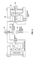
- FIG. 9 shows a possible detection scheme for the first embodiment.
- an electron multiplier tube 80 is disposed at the center of the central cylinder 52 . Ions 64 passing through the ejection slit 58 travel to the central axis 62 where they curve toward a conversion dynode 82 and are then detected by an electron multiplier tube 80 .
- a voltage difference may be applied between a detection wire at the central axis 62 and the housing or central cylinder 52 which may enhance ion detection.
- the use of a Faraday-type detector may also facilitate higher operating pressures that are not now possible in ion traps.
- the lathing operations that are needed to machine the cylindrical toroidal ion trap 50 of the present invention are among the most accurate that can be done using conventional machining techniques. Accordingly, maintaining electrode shape and alignment accuracy is easier than it is for other types of ions traps using curved or hyperbolic surfaces.
- cylindrical toroidal ion trap 50 of the present invention may be manufactured using microfabrication techniques because of the cylindrical and planar shapes of electrodes, and the perpendicular arrangement of the electrodes.
- the ratio of radii 70 and 72 can vary greatly.
- a large major toroidal radius 70 reduces curvature of the wall 56 , which may make it easier to create the desired shape in the electric fields of the trapping volume 60 .
- the major toroidal radius 70 does not need to be reduced in order to expect higher operating pressure.
- the operating pressure may scale as the mean free path of ions 64 in the ion trap as compared with the characteristic dimensions of the trapping volume 60 .
- the use of Faraday-type detectors is not limited to high vacuum situations. Accordingly, the present invention lends itself to a large central cylinder 52 , but with very small trapping volume 60 dimensions. The result is a high aspect-ratio ion trap providing excellent sensitivity.
- toroidal ion trap mass analyzer as described above are for illustration purposes only.
- the present invention should not be considered to be limited by the specific dimensions or other operational parameters given, but should be regarded as examples only. Many dimensions and operational parameters may be modified and the mass analyzer will still operate as desired, in accordance with the principles of the present invention.
- Utilizing cylindrical electrodes enables the present invention to also be miniaturized.
- One of the factors that makes miniaturization possible is that the electrodes 56 , 66 , 66 and 68 have geometries that are simple to manufacture as opposed to the hyperbolic electrodes of the prior art.
- FIG. 9 shows an electron gun 84 that may introduce ions 64 into the trapping volume 60 through an injection port 86 passing through the outside electrode 68 .
- the electron gun 84 may be positioned at any appropriate location that provides access to the trapping volume 60 .
- Scaling the present invention in order to obtain a miniaturized cylindrical toroidal ion trap is not a straight-forward task, and the generation or introduction of ions is an important aspect of the present invention. It is desirable to have a system capable of trapping and detecting ions that are created externally as well as internally.
- an Omega-trap and a Rho-trap were conceived for introducing ions into the trapping volume 60 .
- the names of the traps are derived from the shape of the electrodes.
- the Omega-trap 90 is shown in FIG. 10 and the Rho-trap 110 is shown in FIG. 12 from a top viewpoint.
- the Omega-trap 90 and the Rho-trap 110 are formed of at least two RF electrodes 92 with an AC electrode 94 disposed inbetween. Both traps may be increased in size by adding additional layers, with an RF electrode 92 always being on the top and bottom of a stack.
- FIGS. 10 and 12 shows that there is a multi-layer cylindrical toroid structure that is formed by a circular ring that forms the RF electrode 92 that is disposed on the top and bottom of the ion traps.
- the RF electrodes 92 overlap and extend further inwards toward a central axis than a middle AC electrode 94 disposed between the two RF electrodes 92 .
- the RF electrodes 92 are coaxial with the AC electrode 94 .
- An inner diameter 100 of the two RF electrodes 92 is smaller than an inner diameter 102 of the AC electrode 94 . It should also be recognized that the two RF electrodes 92 overlap the entire ring-structure of the AC electrode 94 .
- the trapping volume 60 shown in FIG. 14 is where the two RF electrodes 92 overlap the thicker AC electrode 94 that has a larger inner diameter.
- the difference between the Omega-trap 90 and the Rho-trap 110 may be in the placement of a linear ion guide 96 .
- the linear ion guide 96 is disposed perpendicular to the path of the trapping volume 60 around the central cylinder 52 .
- the linear ion guide 96 is disposed so as to be tangential to the path of the trapping volume 60 around the central cylinder 52 .
- the Rho-trap 110 design may provide advantages over the Omega-trap 90 design simply because of the placement of the linear ion guide 96 . It may be easier to introduce ions into a trapping volume 60 using the tangentially placed linear ion guide 96 .
- linear ion guide 96 may also vary between the strictly tangential alignment and the strictly perpendicular alignment.
- the linear ion guide 96 can enter the trapping volume from any angle between zero and 90 degrees.
- FIG. 14 is a profile view of what can be either the first embodiment shown in FIG. 5 , the Omega-trap 90 or the Rho-trap 110 , and demonstrates the ability to create a stacked array of electrodes that form the ion traps.
- FIG. 14 demonstrates that the smallest configuration may be comprised of an RF electrode 92 on top and an RF electrode 92 on the bottom, and an AC electrode 94 disposed in between the two RF electrodes 92 .
- a central cylinder 52 is disposed in the center of the electrodes 92 , 94 .
- FIG. 11 is a perspective view of the Omega-trap 90 .
- FIG. 13 is a perspective view of the Rho-trap 110 .
- the Omega-trap 90 and the Rho-trap 110 are miniature versions of the cylindrical toroidal ion trap 50 but with the addition of a means for introducing ions into the traps, with the names being derived from the shape of the ion traps.
- the RF electrodes 92 of the Omega-trap 90 and Rho-trap 110 may be constructed of sheet metal or another thin metal of uniform thickness. Sheet metal may be used because of the high thickness tolerances that can be maintained. Using sheet metal, very small trapping dimensions can be achieved while maintaining a relatively large trapping volume 60 (see FIG. 14 ) with a minimal or no loss in performance.
- the AC electrode 94 may be made from sheet metal or it may be machined from thicker metal using conventional machining techniques.
- Both the Omega-trap 90 and the Rho-trap 110 are shaped so as to provide the linear ion guide 96 , enabling ions that are generated externally or internally to be collected and guided into the trapping volume 60 .
- the ions may be collected externally using a method such as electrospray, thermal desorption/ionization, laser ablation/ionization, etc., or internally using a method such as electron impact, glow/corona discharge, chemical ionization, etc.
- an end-cap 98 on both the Omega-trap 90 and the Rho-trap 110 enables ions to be confined in the trapping volume 60 without escaping.
- the end-cap 98 may also be gated to enable externally generated ions to accumulate in the trapping volume 60 until a mass scan is performed. Gating may be most beneficial when performing a tandem mass analysis, aiding in the reduction of chemical noise.
- the use of cylindrical electrodes manufactured from sheet metal enables the Omega-trap 90 and the Rho-trap 110 designs to be layered or stacked, effectively creating multiple coincident toroidal trapping volumes. While the toroidal trapping volume already has an advantageously large trapping volume, some of that volume is lost when the minor trapping radius is reduced in a miniature cylindrical toroidal ion trap created from the Omega-trap 90 or the Rho-trap 110 designs.
- the loss of trapping volume 60 may be compensated for and may enhance the trapping volume by several factors.
- ion ejection will occur radially for each toroidal trapping layer, creating several axial points in which the ejected ions would occur along the length of the central axis 62 .
- the use of a Faraday-type wire detector may be ideal for this cylindrical toroidal ion trap.
- arrayed cylindrical toroidal ion traps are also possible and may provide some advantages. For instance, with either stacked traps or concentric traps, it may be possible to transfer ions between traps, allowing tandem-in space experiments. In such experiments, ions can be isolated by mass in one trap, fragmented in the next trap, and the fragment ions transferred into yet another trap for mass analysis. The order in which specific procedures are performed on the ions may also be changed as desired. Another possible advantage of an array of traps is that sensitivity would be enhanced with multiple traps acting in parallel.
- Omega-trap 90 and the Rho-trap 110 could not be constructed using the hyperbolic surfaces of conventional toroidal ion traps. Furthermore, it is a simple matter to change the size of the toroidal trapping volume 60 by simply changing the length, thickness or spacing of the RF electrodes 92 and the AC electrodes 94 and thereby obtain the desired asymmetric arrangement of cylindrical and planar electrodes that will generate the desired electric fields that will elect ions in the desired path.
- the embodiments of the present invention are directed toward a trapping volume formed as a ring with a rectangular cross-section, the trapping volume formed from two electrodes having complementary arcuate surfaces 56 , 68 forming opposite sides of the trapping volume, and two other electrodes having planar surfaces forming flattened and ring-like disks 66 , 66 that form the other two sides of the trapping volume 60 .
- the two planar electrodes 66 , 66 and two complementary arcuate electrodes 56 , 68 may have substantially smooth and regular surfaces without artifacts. These surfaces are designed as such not only to simplify the manufacturing process, but to enable the trapping volume to be miniaturized using state of the art manufacturing techniques.
- one or more of the arcuate electrodes 56 , 68 or the two RF electrodes 66 may be given a hyperbolic surface, and still take advantage of the principles of the present invention, and should be considered to be within the scope of the present invention.
Landscapes
- Chemical & Material Sciences (AREA)
- Analytical Chemistry (AREA)
- Electron Tubes For Measurement (AREA)
- Other Investigation Or Analysis Of Materials By Electrical Means (AREA)
Abstract
Description
Claims (33)
Priority Applications (1)
| Application Number | Priority Date | Filing Date | Title |
|---|---|---|---|
| US13/589,988 US8642955B2 (en) | 2011-08-18 | 2012-08-20 | Toroidal ion trap mass analyzer with cylindrical electrodes |
Applications Claiming Priority (3)
| Application Number | Priority Date | Filing Date | Title |
|---|---|---|---|
| US201161575295P | 2011-08-18 | 2011-08-18 | |
| US201261634027P | 2012-02-22 | 2012-02-22 | |
| US13/589,988 US8642955B2 (en) | 2011-08-18 | 2012-08-20 | Toroidal ion trap mass analyzer with cylindrical electrodes |
Publications (2)
| Publication Number | Publication Date |
|---|---|
| US20130214152A1 US20130214152A1 (en) | 2013-08-22 |
| US8642955B2 true US8642955B2 (en) | 2014-02-04 |
Family
ID=47715515
Family Applications (1)
| Application Number | Title | Priority Date | Filing Date |
|---|---|---|---|
| US13/589,988 Active US8642955B2 (en) | 2011-08-18 | 2012-08-20 | Toroidal ion trap mass analyzer with cylindrical electrodes |
Country Status (2)
| Country | Link |
|---|---|
| US (1) | US8642955B2 (en) |
| WO (1) | WO2013026063A1 (en) |
Cited By (2)
| Publication number | Priority date | Publication date | Assignee | Title |
|---|---|---|---|---|
| US20150137010A1 (en) * | 2013-11-14 | 2015-05-21 | Mapper Lithography Ip B.V. | Multi-electrode stack arrangement |
| US20150136970A1 (en) * | 2012-05-18 | 2015-05-21 | Micromass Uk Limited | Orthogonal Acceleration Coaxial Cylinder Time of Flight Mass Analyser |
Families Citing this family (5)
| Publication number | Priority date | Publication date | Assignee | Title |
|---|---|---|---|---|
| US10586625B2 (en) | 2012-05-14 | 2020-03-10 | Asml Netherlands B.V. | Vacuum chamber arrangement for charged particle beam generator |
| CN104900474B (en) * | 2015-05-26 | 2017-02-01 | 清华大学深圳研究生院 | Serially-connected ion trap |
| WO2018211611A1 (en) * | 2017-05-17 | 2018-11-22 | 株式会社島津製作所 | Ion detection device and mass spectrography device |
| DE102019215148B4 (en) | 2019-10-01 | 2022-04-14 | Leybold Gmbh | Ion trap with ring-shaped ion storage space and mass spectrometer |
| US20230253199A1 (en) * | 2022-02-04 | 2023-08-10 | Perkinelmer Health Sciences, Inc. | Toroidal ion trap |
Citations (6)
| Publication number | Priority date | Publication date | Assignee | Title |
|---|---|---|---|---|
| US20030089846A1 (en) | 2000-05-25 | 2003-05-15 | Cooks Robert G. | Ion trap array mass spectrometer |
| US20040149903A1 (en) | 2003-01-31 | 2004-08-05 | Yang Wang | Ion trap mass spectrometry |
| US6838666B2 (en) | 2003-01-10 | 2005-01-04 | Purdue Research Foundation | Rectilinear ion trap and mass analyzer system and method |
| US20080017794A1 (en) | 2006-07-18 | 2008-01-24 | Zyvex Corporation | Coaxial ring ion trap |
| US20080128605A1 (en) | 2002-12-02 | 2008-06-05 | Griffin Analytical Technologies, Inc. | Mass spectrometers |
| US7872228B1 (en) | 2008-06-18 | 2011-01-18 | Bruker Daltonics, Inc. | Stacked well ion trap |
-
2012
- 2012-08-20 US US13/589,988 patent/US8642955B2/en active Active
- 2012-08-20 WO PCT/US2012/051615 patent/WO2013026063A1/en not_active Ceased
Patent Citations (6)
| Publication number | Priority date | Publication date | Assignee | Title |
|---|---|---|---|---|
| US20030089846A1 (en) | 2000-05-25 | 2003-05-15 | Cooks Robert G. | Ion trap array mass spectrometer |
| US20080128605A1 (en) | 2002-12-02 | 2008-06-05 | Griffin Analytical Technologies, Inc. | Mass spectrometers |
| US6838666B2 (en) | 2003-01-10 | 2005-01-04 | Purdue Research Foundation | Rectilinear ion trap and mass analyzer system and method |
| US20040149903A1 (en) | 2003-01-31 | 2004-08-05 | Yang Wang | Ion trap mass spectrometry |
| US20080017794A1 (en) | 2006-07-18 | 2008-01-24 | Zyvex Corporation | Coaxial ring ion trap |
| US7872228B1 (en) | 2008-06-18 | 2011-01-18 | Bruker Daltonics, Inc. | Stacked well ion trap |
Cited By (7)
| Publication number | Priority date | Publication date | Assignee | Title |
|---|---|---|---|---|
| US20150136970A1 (en) * | 2012-05-18 | 2015-05-21 | Micromass Uk Limited | Orthogonal Acceleration Coaxial Cylinder Time of Flight Mass Analyser |
| US20150170897A1 (en) * | 2012-05-18 | 2015-06-18 | Micromass Uk Limited | Orthogonal Acceleration Coaxial Cylinder Time of Flight Mass Analyser |
| US9721779B2 (en) * | 2012-05-18 | 2017-08-01 | Micromass Uk Limited | Orthogonal acceleration coaxial cylinder time of flight mass analyser |
| US9728391B2 (en) * | 2012-05-18 | 2017-08-08 | Micromass Uk Limited | Orthogonal acceleration coaxial cylinder time of flight mass analyser |
| US9978577B2 (en) | 2012-05-18 | 2018-05-22 | Micromass Uk Limited | Orthogonal acceleration coaxial cylinder time of flight mass analyser |
| US20150137010A1 (en) * | 2013-11-14 | 2015-05-21 | Mapper Lithography Ip B.V. | Multi-electrode stack arrangement |
| US9355751B2 (en) * | 2013-11-14 | 2016-05-31 | Mapper Lithography Ip B.V. | Multi-electrode stack arrangement |
Also Published As
| Publication number | Publication date |
|---|---|
| US20130214152A1 (en) | 2013-08-22 |
| WO2013026063A1 (en) | 2013-02-21 |
Similar Documents
| Publication | Publication Date | Title |
|---|---|---|
| US8642955B2 (en) | Toroidal ion trap mass analyzer with cylindrical electrodes | |
| US7375320B2 (en) | Virtual ion trap | |
| US7868289B2 (en) | Mass spectrometer ion guide providing axial field, and method | |
| US8637815B2 (en) | Charged particle analysers and methods of separating charged particles | |
| US9412578B2 (en) | Charged particle analysers and methods of separating charged particles | |
| US7723679B2 (en) | Coaxial hybrid radio frequency ion trap mass analyzer | |
| GB2437609A (en) | A multi-turn time-of-flight mass analyzer comprising perpendicular electric sectors | |
| WO2011086430A1 (en) | Ion trap mass spectrometer | |
| US11201046B2 (en) | Orthogonal acceleration time-of-flight mass spectrometer and lead-in electrode for the same | |
| JP7018525B2 (en) | Ion guide for mass spectrometer and ion source using it | |
| JPWO2008117333A1 (en) | Mass spectrometer | |
| US7381947B2 (en) | Electrode networks for parallel ion traps | |
| CN109346396B (en) | Mass Spectrometry Systems for Improved Ion Detection Efficiency | |
| US20240136167A1 (en) | Mass spectrometer and method | |
| US20130015340A1 (en) | Multipole assembly having a main mass filter and an auxiliary mass filter | |
| CN103972022B (en) | A kind of linear ion hydrazine containing high-order field composition | |
| US7166837B2 (en) | Apparatus and method for ion fragmentation cut-off | |
| CN213366528U (en) | Prismatic Linear Ion Trap Mass Analyzer | |
| US11791149B2 (en) | Axially progressive lens for transporting charged particles | |
| CN210182330U (en) | Linear mass analyzer | |
| RU2734290C1 (en) | Open dynamically harmonized ion trap for ion cyclotron resonance mass spectrometer | |
| CN111816545A (en) | Prismatic Linear Ion Trap Mass Analyzer | |
| CN121545985A (en) | A roll-up ion transport device based on a flexible printed circuit board | |
| Wang | Halo ion trap mass spectrometry: Design, instrumentation, and performance |
Legal Events
| Date | Code | Title | Description |
|---|---|---|---|
| AS | Assignment |
Owner name: BRIGHAM YOUNG UNIVERSITY, UTAH Free format text: ASSIGNMENT OF ASSIGNORS INTEREST;ASSIGNORS:AUSTIN, DANIEL E.;TAYLOR, NICHOLAS R.;SIGNING DATES FROM 20120906 TO 20120919;REEL/FRAME:029177/0526 |
|
| STCF | Information on status: patent grant |
Free format text: PATENTED CASE |
|
| FPAY | Fee payment |
Year of fee payment: 4 |
|
| FEPP | Fee payment procedure |
Free format text: ENTITY STATUS SET TO UNDISCOUNTED (ORIGINAL EVENT CODE: BIG.); ENTITY STATUS OF PATENT OWNER: LARGE ENTITY |
|
| MAFP | Maintenance fee payment |
Free format text: PAYMENT OF MAINTENANCE FEE, 8TH YEAR, LARGE ENTITY (ORIGINAL EVENT CODE: M1552); ENTITY STATUS OF PATENT OWNER: LARGE ENTITY Year of fee payment: 8 |
|
| FEPP | Fee payment procedure |
Free format text: MAINTENANCE FEE REMINDER MAILED (ORIGINAL EVENT CODE: REM.); ENTITY STATUS OF PATENT OWNER: LARGE ENTITY |
|
| FEPP | Fee payment procedure |
Free format text: 11.5 YR SURCHARGE- LATE PMT W/IN 6 MO, LARGE ENTITY (ORIGINAL EVENT CODE: M1556); ENTITY STATUS OF PATENT OWNER: LARGE ENTITY Free format text: 11.5 YR SURCHARGE- LATE PMT W/IN 6 MO, SMALL ENTITY (ORIGINAL EVENT CODE: M2556); ENTITY STATUS OF PATENT OWNER: SMALL ENTITY |
|
| MAFP | Maintenance fee payment |
Free format text: PAYMENT OF MAINTENANCE FEE, 12TH YEAR, LARGE ENTITY (ORIGINAL EVENT CODE: M1553); ENTITY STATUS OF PATENT OWNER: LARGE ENTITY Year of fee payment: 12 Free format text: PAYMENT OF MAINTENANCE FEE, 12TH YR, SMALL ENTITY (ORIGINAL EVENT CODE: M2553); ENTITY STATUS OF PATENT OWNER: SMALL ENTITY Year of fee payment: 12 |
|
| FEPP | Fee payment procedure |
Free format text: ENTITY STATUS SET TO SMALL (ORIGINAL EVENT CODE: SMAL); ENTITY STATUS OF PATENT OWNER: SMALL ENTITY |