US8635988B2 - Variable valve device for internal combustion engine - Google Patents
Variable valve device for internal combustion engine Download PDFInfo
- Publication number
- US8635988B2 US8635988B2 US12/940,236 US94023610A US8635988B2 US 8635988 B2 US8635988 B2 US 8635988B2 US 94023610 A US94023610 A US 94023610A US 8635988 B2 US8635988 B2 US 8635988B2
- Authority
- US
- United States
- Prior art keywords
- intake
- phase
- cam
- camshaft
- internal combustion
- Prior art date
- Legal status (The legal status is an assumption and is not a legal conclusion. Google has not performed a legal analysis and makes no representation as to the accuracy of the status listed.)
- Expired - Fee Related, expires
Links
Images


Classifications
-
- F—MECHANICAL ENGINEERING; LIGHTING; HEATING; WEAPONS; BLASTING
- F01—MACHINES OR ENGINES IN GENERAL; ENGINE PLANTS IN GENERAL; STEAM ENGINES
- F01L—CYCLICALLY OPERATING VALVES FOR MACHINES OR ENGINES
- F01L1/00—Valve-gear or valve arrangements, e.g. lift-valve gear
- F01L1/34—Valve-gear or valve arrangements, e.g. lift-valve gear characterised by the provision of means for changing the timing of the valves without changing the duration of opening and without affecting the magnitude of the valve lift
- F01L1/344—Valve-gear or valve arrangements, e.g. lift-valve gear characterised by the provision of means for changing the timing of the valves without changing the duration of opening and without affecting the magnitude of the valve lift changing the angular relationship between crankshaft and camshaft, e.g. using helicoidal gear
- F01L1/3442—Valve-gear or valve arrangements, e.g. lift-valve gear characterised by the provision of means for changing the timing of the valves without changing the duration of opening and without affecting the magnitude of the valve lift changing the angular relationship between crankshaft and camshaft, e.g. using helicoidal gear using hydraulic chambers with variable volume to transmit the rotating force
-
- F—MECHANICAL ENGINEERING; LIGHTING; HEATING; WEAPONS; BLASTING
- F02—COMBUSTION ENGINES; HOT-GAS OR COMBUSTION-PRODUCT ENGINE PLANTS
- F02D—CONTROLLING COMBUSTION ENGINES
- F02D13/00—Controlling the engine output power by varying inlet or exhaust valve operating characteristics, e.g. timing
- F02D13/02—Controlling the engine output power by varying inlet or exhaust valve operating characteristics, e.g. timing during engine operation
- F02D13/0223—Variable control of the intake valves only
- F02D13/0234—Variable control of the intake valves only changing the valve timing only
- F02D13/0238—Variable control of the intake valves only changing the valve timing only by shifting the phase, i.e. the opening periods of the valves are constant
-
- F—MECHANICAL ENGINEERING; LIGHTING; HEATING; WEAPONS; BLASTING
- F01—MACHINES OR ENGINES IN GENERAL; ENGINE PLANTS IN GENERAL; STEAM ENGINES
- F01L—CYCLICALLY OPERATING VALVES FOR MACHINES OR ENGINES
- F01L1/00—Valve-gear or valve arrangements, e.g. lift-valve gear
- F01L1/02—Valve drive
- F01L1/04—Valve drive by means of cams, camshafts, cam discs, eccentrics or the like
- F01L1/047—Camshafts
- F01L2001/0471—Assembled camshafts
- F01L2001/0473—Composite camshafts, e.g. with cams or cam sleeve being able to move relative to the inner camshaft or a cam adjusting rod
-
- F—MECHANICAL ENGINEERING; LIGHTING; HEATING; WEAPONS; BLASTING
- F01—MACHINES OR ENGINES IN GENERAL; ENGINE PLANTS IN GENERAL; STEAM ENGINES
- F01L—CYCLICALLY OPERATING VALVES FOR MACHINES OR ENGINES
- F01L1/00—Valve-gear or valve arrangements, e.g. lift-valve gear
- F01L1/02—Valve drive
- F01L1/04—Valve drive by means of cams, camshafts, cam discs, eccentrics or the like
- F01L1/047—Camshafts
- F01L2001/0478—Torque pulse compensated camshafts
-
- F—MECHANICAL ENGINEERING; LIGHTING; HEATING; WEAPONS; BLASTING
- F01—MACHINES OR ENGINES IN GENERAL; ENGINE PLANTS IN GENERAL; STEAM ENGINES
- F01L—CYCLICALLY OPERATING VALVES FOR MACHINES OR ENGINES
- F01L1/00—Valve-gear or valve arrangements, e.g. lift-valve gear
- F01L1/34—Valve-gear or valve arrangements, e.g. lift-valve gear characterised by the provision of means for changing the timing of the valves without changing the duration of opening and without affecting the magnitude of the valve lift
- F01L1/344—Valve-gear or valve arrangements, e.g. lift-valve gear characterised by the provision of means for changing the timing of the valves without changing the duration of opening and without affecting the magnitude of the valve lift changing the angular relationship between crankshaft and camshaft, e.g. using helicoidal gear
- F01L2001/34486—Location and number of the means for changing the angular relationship
- F01L2001/34489—Two phasers on one camshaft
-
- F—MECHANICAL ENGINEERING; LIGHTING; HEATING; WEAPONS; BLASTING
- F01—MACHINES OR ENGINES IN GENERAL; ENGINE PLANTS IN GENERAL; STEAM ENGINES
- F01L—CYCLICALLY OPERATING VALVES FOR MACHINES OR ENGINES
- F01L2800/00—Methods of operation using a variable valve timing mechanism
- F01L2800/06—Timing or lift different for valves of same cylinder
-
- Y—GENERAL TAGGING OF NEW TECHNOLOGICAL DEVELOPMENTS; GENERAL TAGGING OF CROSS-SECTIONAL TECHNOLOGIES SPANNING OVER SEVERAL SECTIONS OF THE IPC; TECHNICAL SUBJECTS COVERED BY FORMER USPC CROSS-REFERENCE ART COLLECTIONS [XRACs] AND DIGESTS
- Y02—TECHNOLOGIES OR APPLICATIONS FOR MITIGATION OR ADAPTATION AGAINST CLIMATE CHANGE
- Y02T—CLIMATE CHANGE MITIGATION TECHNOLOGIES RELATED TO TRANSPORTATION
- Y02T10/00—Road transport of goods or passengers
- Y02T10/10—Internal combustion engine [ICE] based vehicles
- Y02T10/12—Improving ICE efficiencies
Definitions
- This present invention relates to a variable valve device for internal combustion engines, and more particularly, techniques for optimizing valve opening/closing timings of intake and exhaust valves.
- cam phase variable mechanisms as a variable valve device for varying valve opening/closing timings (cam phases).
- cam phase variable mechanisms are applied to an engine having each cylinder provided with a plurality of intake valves and the valve opening/closing timings of all intake valves as well as only some of the intake valves are varied (split) in accordance with the operating condition of the engine (Japanese Laid-open Patent Publication No. 2009-144521).
- valve opening/closing timings of only some of the intake valves associated with the individual cylinders can be varied in this manner, the multiple intake valves can be made to open continuously as a whole, whereby highly flexible valve control can be executed so that the overall valve open period of the intake valves may be prolonged, making it possible to improve the operational performance of the engine.
- the closing timing of the intake valve it is preferable to set the closing timing of the intake valve to a most retarded position when the internal combustion engine is in a low speed and load state because pumping losses can be reduced by retarding the closing timing of the intake valve.
- the inventors' research discloses that, if one of the valves, whose opening/closing timing is variable, is controlled to the most retarded position as described above during an extremely low speed and load period after the warm-up of the internal combustion engine as in a hot idling state, this reduces pumping losses but incurs phenomena, such as unstable combustion and inefficient fuel consumption. It is undesirable to deteriorate combustion stability and fuel consumption during the extremely low speed and load period after the warm-up of the internal combustion engine. Considering that the idling is frequently conducted, a sufficient improvement cannot be seen in the operating performance of the internal combustion engine.
- An object of the present invention is to provide a variable valve device for an internal combustion engine capable of preventing a reduction in combustion stability and fuel efficiency in pumping-loss reduction operations of the internal combustion engine, thereby improving performance of the internal combustion engine.
- the invention provides a variable valve device for an internal combustion engine comprising; a cam phase variable mechanism in which each cylinder includes a first intake valve driven by a first intake cam and a second intake valve driven by a second intake cam, the mechanism being capable of varying a phase of the second intake cam relative to the first intake cam, and a phase variable control unit that controls the cam phase variable mechanism, wherein the cam phase variable mechanism is formed by turnably disposing an inner camshaft in an outer camshaft formed of a pipe, has a intake camshaft that can be driven by crank output of the internal combustion engine, is provided with the first intake cam in a peripheral area of the outer camshaft, is provided with the second intake cam so as to be turnable around an axis of the outer camshaft, and varies the phase of the second intake cam on the basis of the first intake cam at a relative displacement of the outer and inner camshafts; and under predetermined operating conditions of the internal combustion engine, the phase variable control unit varies the phase of the second intake cam relative to
- the width of fluctuation of torque on the intake camshaft varies depending on the relative displacement of the inner camshaft relative to the outer camshaft. Greater fluctuation of torque leads to greater likelihood of transition from lubricant's fluid lubrication to boundary lubrication, and thus, increased friction on the intake camshaft.
- the second cam is controlled to take a phase entailing a minimum fluctuation of torque on the intake camshaft, it leads to reduced friction on the intake camshaft, which leads to increased combustion stability, and thus, increased fuel efficiency.
- FIG. 1 illustrates a schematic construction of a variable valve device for an internal combustion engine according to the present invention
- FIG. 2 illustrates a map used for controlling the operations of first and second cam phase variable mechanisms
- FIGS. 3( a ), 3 ( b ) and 3 ( c ) individually illustrate the relationship of the crank angle of the engine with the lift amounts of first and second intake valves and an exhaust valve during the execution of operation control in a low-speed, low-load region;
- FIG. 4 is a Stribeck diagram
- FIG. 5 illustrates the relationship of the amount of split between the first and second intake valves with torque applied to an intake camshaft
- FIG. 6 illustrates the relationship of the amount of split between the first and second intake valves with torque applied to an intake and an exhaust camshaft.
- FIG. 1 schematically illustrates the construction of a variable valve device for an internal combustion engine according to the present invention. More particularly, FIG. 1 is a top view showing the internal structure of a cylinder head 2 of an engine 1 .
- the engine 1 is, for example an in-line four-cylinder engine with a DOHC valve train. As seen in FIG. 1 , an exhaust camshaft 3 and an intake camshaft 4 , rotatably supported inside the cylinder head 2 , have cam sprockets 5 , 6 mounted thereon, respectively. The cam sprockets 5 , 6 are connected to a crankshaft, not shown, by a chain 7 .
- two intake valves 9 , 10 and two exhaust valves 14 , 14 are provided for each cylinder 8 of the engine 1 .
- first and second intake cams 11 , 12 are provided alternately, and the two intake valves 9 , 10 for each cylinder 8 are driven by the first and second intake cams 11 , 12 , respectively.
- the two exhaust valves 14 , 14 for each cylinder 8 are driven by exhaust cams 13 fixed on the exhaust camshaft 3 .
- the intake camshaft 4 is a double-structured shaft consisting of a hollow outer camshaft and an inner camshaft arranged inside the outer camshaft.
- the inner camshaft is coaxially arranged inside the outer camshaft with a slight clearance.
- the inner and outer camshafts thus arranged are rotatably received in cam journals 23 provided at the cylinder head 2 of the engine 1 .
- Each first intake cam 11 is fixed to the outer camshaft.
- Each second intake cam 12 is seated on the outer camshaft and fixed to the inner camshaft by a fixing pin fitted through a circumferentially-extending through-hole formed in the outer camshaft. Consequently, the first intake cams 11 rotate with the outer camshaft, while the second intake cams 12 rotate with the inner camshaft, and the inner camshaft with the second intake cams 12 is allowed to turn relative to the outer camshaft.
- the intake camshaft 4 is provided with a first cam phase variable mechanism 30 and a second cam phase variable mechanism (“cam phase variable mechanism” mentioned in claims) 31 .
- the first and second cam phase variable mechanisms 30 , 31 are each formed of a known vane-type hydraulic actuator, for example.
- the vane-type hydraulic actuator is composed of a vane rotor rotatably arranged inside a cylindrical housing (cover), and designed such that the relative displacement of the vane relative to the housing varies depending on the amount of a working fluid supplied from a hydraulic unit 50 to inside the housing via a solenoid-operated hydraulic valve 52 or 54 , or in other words, the pressure of the working fluid inside the housing.
- the first cam phase variable mechanism 30 is arranged at the front end of the intake camshaft 4 , with the cam sprocket 6 fixed to the housing, and the outer camshaft fixed to the vane rotor.
- the second cam phase variable mechanism 31 is arranged at the rear end of the intake camshaft 4 , with the outer camshaft fixed to the housing, and the inner camshaft fixed to the vane rotor.
- the first cam phase variable mechanism 30 can vary the relative displacement of the outer camshaft relative to the cam sprocket 6
- the second cam phase variable mechanism 31 can vary the relative displacement of the inner camshaft relative to the outer camshaft
- the first cam phase variable mechanism 30 can vary the opening/closing timing of the first intake valves 9 and the opening/closing timing of the second intake valves 10 , relative to the opening/closing timing of the exhaust valves 14
- the second cam phase variable mechanism 31 can vary the phase difference (amount of split) between the opening/closing timing of the first intake valves 9 and the opening/closing timing of the second intake valves 10 .
- the first cam phase variable mechanism 30 can be controlled by regulating the valve position of the hydraulic valve 52 on the basis of information from the first cam sensor 32 .
- the intake camshaft 4 extends through a rear wall 2 a of the cylinder head 2 , and the second cam phase variable mechanism 31 is arranged outside the cylinder head 2 and covered with an actuator cover 40 .
- a second cam sensor 45 for detecting rotating timing of the vaned rotor of the second cam phase variable mechanism 31 , thereby detecting the actual relative displacement of the inner camshaft.
- the actual relative displacement between the inner and outer camshafts can be obtained on the basis of information from the first and second cam sensors 32 and 45 , and the second cam phase variable mechanism 31 can be controlled by regulating the valve position of the solenoid hydraulic valve 54 on the basis of the actual relative displacement thus obtained.
- An electronic control unit (ECU) 60 controls the engine 1 in various aspects, and comprises a CPU, memory, etc.
- various sensors such as an accelerator position sensor (APS) 62 for detecting the position of the accelerator of the engine 1 , and a crank angle sensor 64 for detecting a crank angle, in addition to the aforementioned first and second cam sensors 32 and 45 .
- APS accelerator position sensor
- crank angle sensor 64 for detecting a crank angle
- various devices including the aforementioned solenoid hydraulic valves 52 , 54 .
- An engine load is obtained on the basis of accelerator position information from the APS 62
- an engine speed (rpm) Ne is obtained on the basis of crank angle information from the crank angle sensor 64 .
- variable valve device for the internal combustion engine according to the present invention structured as described above, functions will be described.
- the ECU 60 (“phase variable control unit” in claims) controls the first and second cam phase variable mechanisms 30 and 31 according to a map shown in FIG. 2 , on the basis of operating conditions of the engine 1 , specifically engine load and engine speed Ne.
- the first and second cam phase variable mechanisms 30 and 31 are controlled depending on delimited operating regions of the engine 1 , i.e., a start and warm-up operating region X, a low-speed low-load operating region A, a low-speed high-load operating region B, and a high-speed operating region C.
- the first cam phase variable mechanism 30 (indicated as “1ST VVT” in the drawings) is held at the most retarded phase and the second cam phase variable mechanism (indicated as “2ND VVT” in the drawings) 31 is held at the most advanced phase, each by a lock pin.
- the first cam phase variable mechanism 30 is held at the most retarded phase and the second cam phase variable mechanism 31 is controlled to take a phase determined depending on the engine speed and load. Specifically, as long as the engine speed Ne is greater than or equal to a specified value N 0 and less than a specified value N 1 , the hydraulic pressure supplied from the hydraulic unit 50 is low.
- the first cam phase variable mechanism 30 is held at the most retarded phase by the lock pin or hydraulic pressure, while the second cam phase variable mechanism 31 is controlled to take a phase determined depending on the engine speed and load, considering that the second cam phase variable mechanism 31 , which is arranged to vary the opening/closing timing of a smaller number of valves, compared with the first cam phase variable mechanism 30 , is higher in controllability than the first cam phase variable mechanism 30 .
- the first cam phase variable mechanism 30 is held at the most retarded phase, while the second cam phase variable mechanism 31 is controlled to take a phase determined depending on the engine speed and load.
- the first cam phase variable mechanism 30 is controlled to take a retarded phase determined depending on the engine speed and load, while the second cam phase variable mechanism 31 is held at the most advanced phase.
- the engine load which is obtained from accelerator position information from the APS 62
- the engine speed Ne is greater than or equal to the value N 1 and less than the value N 2
- the first cam phase variable mechanism 30 is controlled to take a retarded phase determined depending on the engine speed and load, while the second cam phase variable mechanism 31 is held at the most advanced phase.
- the first cam phase variable mechanism 30 is held at the most retarded phase, while the second cam phase variable mechanism 31 is held at the most advanced phase.
- the first cam phase variable mechanism 30 is held at the most retarded phase, while the second cam phase variable mechanism 31 is held at the most advanced phase.
- the first cam phase variable mechanism 30 is fixed at the most retarded phase to allow the second cam phase variable mechanism 31 to be controlled preferentially.
- the second cam phase variable mechanism 31 is fixed at the most advanced phase to allow the first cam phase variable mechanism 30 to be controlled preferentially.
- the first cam phase variable mechanism 30 is fixed at the most retarded phase and the second cam phase variable mechanism is fixed at the most advanced phase.
- Fixing at least either of the first and second cam phase variable mechanisms 30 and 31 means that hydraulic pressure is never supplied to both the first and second cam phase variable mechanisms 30 and 31 simultaneously, or in other words, supply of hydraulic pressure can be limited to either of the first and second cam phase variable mechanisms 30 and 31 . Consequently, in any of the operating regions A, B and C, fluctuations in hydraulic pressure are reduced, so that the first and second cam phase variable mechanisms 30 and 31 are both controlled stably and accurately.
- first and second intake valves 9 , 10 This enables the first and second intake valves 9 , 10 to be continuously, smoothly and freely operated, and thus, enables an extended intake valve “open” duration, which enables fine control of intake manifold pressure with satisfactorily reduced pumping losses, leading to increased engine output and reduced fuel consumption.
- the second cam phase variable mechanism 31 While in the central area of the low-load low-speed operating region A, the second cam phase variable mechanism 31 is held at the most retarded phase, in the peripheral area of the operating region A, the second cam phase variable mechanism 31 is controlled to take less retarded phase for the engine load and speed farther away from the center of the region A, as indicated by an arrow.
- the operating region A is divided into an extremely low-load extremely low-speed operating region A 1 and the rest A 2 .
- the operating region A 1 is an extremely low-speed extremely low-load operating region after warm-up (“predetermined extremely low-speed extremely low-load operating region” in claims) and includes a warm idling operating region, while the operating region A 2 is a normal low-speed low-load operating region.
- the extremely low-speed extremely low-load operating region A 1 is included in the peripheral area of the operating region A, not the central area thereof. Consequently, in the extremely low-speed extremely low-load operating region A 1 , the first cam phase variable mechanism 30 is held at the most retarded phase, while the second cam phase variable mechanism 31 is controlled to take a retarded phase determined depending on the engine speed and load within a phase range ensuring pumping-loss reduction operation, or operation with satisfactorily reduced pumping losses (“predetermined pumping-loss reduction operation phase range” in claims; phase (split) range of 20° to 90°, for example).
- FIG. 3 shows how the lift of the first intake valve 9 , the second intake valve 10 and the exhaust valve 14 varies with crank angle, by control in the operating region A.
- the second cam phase variable mechanism 31 is at the most advanced phase, as in the start and warm-up operating region X, so that the second intake valve 10 closes at a less retarded point. This increases the actual compression ratio, thereby increasing ignition performance and combustion stability.
- FIG. 3( b ) is the case in which the engine 1 is in the extremely low-speed extremely low-load operating region A 1 , so that the second cam phase variable mechanism 31 is controlled to take a retarded phase determined depending on the engine speed and load within the pumping-loss reduction operation phase range, so that the second intake valve closes at a more retarded point.
- This not only reduces pumping losses, but also increases combustion stability and thus, fuel efficiency, because staggered “open” periods of the first and second intake valves offers strengthened flow inside the cylinder and such intake valve closing timing offers balanced actual compression ratio.
- 3( c ) is the case in which the engine 1 is in the central area of the operating region A, which is included in the operating region A 2 , so that the second cam phase variable mechanism 31 is held at the most retarded phase to maximize the split, or phase difference between the opening/closing timing of the first intake valve 9 and the opening/closing timing of the second intake valve 10 .
- the second cam phase variable mechanism 31 is controlled to take a retarded phase determined depending on the engine speed and load within the pumping-loss reduction operation phase range. This is because it has been confirmed that if the second cam phase variable mechanism 31 is held at the most retarded phase within the pumping-loss reduction operation phase range to maximize the split between the first intake valve 9 and the second intake valve 10 , it tends to result in reduced combustion stability, and thus, reduced fuel efficiency.
- FIG. 4 there is illustrated what is called a Stribeck diagram showing the relationship of the viscosity of lubricating oil, sliding velocity and fluctuating load ⁇ (viscosity) ⁇ (sliding velocity)/(fluctuating load) ⁇ with the state of lubrication.
- a Stribeck diagram showing the relationship of the viscosity of lubricating oil, sliding velocity and fluctuating load ⁇ (viscosity) ⁇ (sliding velocity)/(fluctuating load) ⁇ with the state of lubrication.
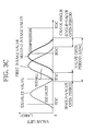
- FIG. 5 shows how the maximum value (solid line) and minimum value (broken line) of oscillating drive torque on the intake camshaft 4 vary depending on the split between the first and second intake cams 11 , 12 .
- FIG. 5 shows that the width of oscillation of the drive torque on the intake camshaft 4 , and thus, the fluctuating load is smallest at a split S 1 .
- fuel consumption of the engine 1 can be reduced by controlling the second cam phase variable mechanism 31 to take a phase (split S 1 ) which is within the pumping-loss reduction operation phase range and results in small drive friction and maximum fuel efficiency.
- FIG. 6 shows how the maximum value (solid line) and minimum value (broken line) of combined drive torque on the exhaust and intake camshafts 3 , 4 vary depending on the split (phase difference) between the first and second intake valves 9 , 10 .
- FIG. 6 shows that the width of oscillation of the combined torque on the exhaust and intake camshafts 3 , 4 , and thus, the load fluctuation is smallest at a split S 1 ′.
- variable valve device for the internal combustion engine according to an embodiment of the present invention has been described.
- the present invention is however not limited to the above-described embodiment.
- a first cam phase variable mechanism 30 for varying the opening/closing timing of the first intake valves 9 and the opening/closing timing of the second intake valve 10 in addition to the second cam phase variable mechanism 31 for varying the phase difference (split) between the opening/closing timing of the first intake valves 9 and the opening/closing timing of the second intake valves 10 , there is provided a first cam phase variable mechanism 30 for varying the opening/closing timing of the first intake valves 9 and the opening/closing timing of the second intake valve 10 , together; the present invention is however satisfactorily applicable to engines provided with only the second cam phase variable mechanism 31 .
- the engine 1 is an in-line four-cylinder engine with a DOHC valve train; the engine 1 is however not limited to the in-line type but may be a V type, and the number of cylinders is not limited to four, although the engine 1 needs to have a DOHC valve train.
Landscapes
- Engineering & Computer Science (AREA)
- Mechanical Engineering (AREA)
- General Engineering & Computer Science (AREA)
- Chemical & Material Sciences (AREA)
- Combustion & Propulsion (AREA)
- Valve Device For Special Equipments (AREA)
- Output Control And Ontrol Of Special Type Engine (AREA)
- Valve-Gear Or Valve Arrangements (AREA)
Abstract
Description
Claims (3)
Applications Claiming Priority (2)
| Application Number | Priority Date | Filing Date | Title |
|---|---|---|---|
| JP2009254911A JP4702574B2 (en) | 2009-11-06 | 2009-11-06 | Variable valve operating device for internal combustion engine |
| JP2009-254911 | 2009-11-06 |
Publications (2)
| Publication Number | Publication Date |
|---|---|
| US20110107987A1 US20110107987A1 (en) | 2011-05-12 |
| US8635988B2 true US8635988B2 (en) | 2014-01-28 |
Family
ID=43629152
Family Applications (1)
| Application Number | Title | Priority Date | Filing Date |
|---|---|---|---|
| US12/940,236 Expired - Fee Related US8635988B2 (en) | 2009-11-06 | 2010-11-05 | Variable valve device for internal combustion engine |
Country Status (5)
| Country | Link |
|---|---|
| US (1) | US8635988B2 (en) |
| EP (1) | EP2320034B1 (en) |
| JP (1) | JP4702574B2 (en) |
| KR (1) | KR101110993B1 (en) |
| CN (1) | CN102052111B (en) |
Families Citing this family (6)
| Publication number | Priority date | Publication date | Assignee | Title |
|---|---|---|---|---|
| JP5609796B2 (en) * | 2011-07-12 | 2014-10-22 | 三菱自動車工業株式会社 | Variable valve gear |
| KR101305188B1 (en) | 2011-12-14 | 2013-09-12 | 현대자동차주식회사 | Engine that actively varies compressioin expansion ratio |
| KR20160064847A (en) | 2014-11-28 | 2016-06-08 | 현대자동차주식회사 | Continuous varible vavle duration apparatus and control method by using the same |
| US10941680B2 (en) * | 2015-12-28 | 2021-03-09 | Eaton Corporation | Discrete variable valve lift engine systems and methods |
| WO2017116918A1 (en) * | 2015-12-28 | 2017-07-06 | Eaton Corporation | Low friction switching roller finger follower for high valve lift |
| CN114412639A (en) * | 2022-01-29 | 2022-04-29 | 湖南大兹动力科技有限公司 | Strong vortex variable Miller cycle internal combustion engine |
Citations (11)
| Publication number | Priority date | Publication date | Assignee | Title |
|---|---|---|---|---|
| JPS60150411A (en) | 1984-01-18 | 1985-08-08 | Mazda Motor Corp | Cylinder number controlling engine |
| US5233948A (en) | 1992-12-10 | 1993-08-10 | Ford Motor Company | Variable cycle engine |
| US5497737A (en) | 1993-10-14 | 1996-03-12 | Nissan Motor Co., Ltd. | Intake and exhaust valves control of internal combustion engine |
| US6009842A (en) * | 1997-10-16 | 2000-01-04 | Daimlerchrysler Ag | Fuel injection system for a multicylinder internal combustion engine with a fuel supply line serving as a high pressure storage device |
| US6885976B2 (en) * | 2001-06-21 | 2005-04-26 | Honda Giken Kogyo Kabushiki Kaisha | Fault determining apparatus, fault determining method and engine control unit for variable valve timing mechanism |
| DE102005024485A1 (en) | 2005-05-27 | 2006-11-30 | Daimlerchrysler Ag | camshaft unit |
| WO2007022737A1 (en) | 2005-08-23 | 2007-03-01 | Mahle International Gmbh | Camshaft |
| US20070169732A1 (en) | 2006-01-26 | 2007-07-26 | Hitachi, Ltd. | Phase controller and cam shaft phase controller for internal combustion engine |
| EP1870583A1 (en) | 2006-06-21 | 2007-12-26 | Peugeot Citroën Automobiles S.A. | method for controlling an internal combustion engine |
| JP2009144521A (en) | 2007-12-11 | 2009-07-02 | Honda Motor Co Ltd | Valve operating apparatus provided with phase control means |
| US8538662B2 (en) * | 2009-11-06 | 2013-09-17 | Mitsubishi Jidosha Kogyo Kabushiki Kaisha | Variable valve device for internal combustion engine |
Family Cites Families (7)
| Publication number | Priority date | Publication date | Assignee | Title |
|---|---|---|---|---|
| JP2800036B2 (en) * | 1989-08-31 | 1998-09-21 | スズキ株式会社 | Variable valve mechanism for internal combustion engine |
| JP3385717B2 (en) * | 1994-05-02 | 2003-03-10 | 日産自動車株式会社 | Variable valve train for internal combustion engine |
| JPH08312392A (en) * | 1995-05-12 | 1996-11-26 | Suzuki Motor Corp | Engine controller |
| US6397813B1 (en) * | 2000-04-28 | 2002-06-04 | Ford Global Technologies, Inc. | Method and apparatus for inducing swirl in an engine cylinder by controlling engine valves |
| JP2005061261A (en) * | 2003-08-08 | 2005-03-10 | Hitachi Unisia Automotive Ltd | Variable valve operating device for internal combustion engine |
| CN100560949C (en) * | 2007-10-23 | 2009-11-18 | 奇瑞汽车股份有限公司 | A method for improving engine idling performance |
| CN201297187Y (en) * | 2008-11-19 | 2009-08-26 | 广州柴油机厂 | A high-power diesel engine camshaft structure with adjustable phase angle |
-
2009
- 2009-11-06 JP JP2009254911A patent/JP4702574B2/en not_active Expired - Fee Related
-
2010
- 2010-11-05 US US12/940,236 patent/US8635988B2/en not_active Expired - Fee Related
- 2010-11-05 KR KR1020100109790A patent/KR101110993B1/en not_active Expired - Fee Related
- 2010-11-05 EP EP10190186.6A patent/EP2320034B1/en not_active Not-in-force
- 2010-11-08 CN CN2010105366887A patent/CN102052111B/en not_active Expired - Fee Related
Patent Citations (13)
| Publication number | Priority date | Publication date | Assignee | Title |
|---|---|---|---|---|
| JPS60150411A (en) | 1984-01-18 | 1985-08-08 | Mazda Motor Corp | Cylinder number controlling engine |
| US5233948A (en) | 1992-12-10 | 1993-08-10 | Ford Motor Company | Variable cycle engine |
| US5497737A (en) | 1993-10-14 | 1996-03-12 | Nissan Motor Co., Ltd. | Intake and exhaust valves control of internal combustion engine |
| US6009842A (en) * | 1997-10-16 | 2000-01-04 | Daimlerchrysler Ag | Fuel injection system for a multicylinder internal combustion engine with a fuel supply line serving as a high pressure storage device |
| US6885976B2 (en) * | 2001-06-21 | 2005-04-26 | Honda Giken Kogyo Kabushiki Kaisha | Fault determining apparatus, fault determining method and engine control unit for variable valve timing mechanism |
| US7827945B2 (en) | 2005-05-27 | 2010-11-09 | Daimler Ag | Camshaft operating unit |
| DE102005024485A1 (en) | 2005-05-27 | 2006-11-30 | Daimlerchrysler Ag | camshaft unit |
| WO2007022737A1 (en) | 2005-08-23 | 2007-03-01 | Mahle International Gmbh | Camshaft |
| DE102005039751A1 (en) | 2005-08-23 | 2007-03-01 | Mahle International Gmbh | camshaft |
| US20070169732A1 (en) | 2006-01-26 | 2007-07-26 | Hitachi, Ltd. | Phase controller and cam shaft phase controller for internal combustion engine |
| EP1870583A1 (en) | 2006-06-21 | 2007-12-26 | Peugeot Citroën Automobiles S.A. | method for controlling an internal combustion engine |
| JP2009144521A (en) | 2007-12-11 | 2009-07-02 | Honda Motor Co Ltd | Valve operating apparatus provided with phase control means |
| US8538662B2 (en) * | 2009-11-06 | 2013-09-17 | Mitsubishi Jidosha Kogyo Kabushiki Kaisha | Variable valve device for internal combustion engine |
Also Published As
| Publication number | Publication date |
|---|---|
| CN102052111B (en) | 2013-05-29 |
| US20110107987A1 (en) | 2011-05-12 |
| CN102052111A (en) | 2011-05-11 |
| EP2320034B1 (en) | 2013-06-05 |
| KR101110993B1 (en) | 2012-02-15 |
| EP2320034A1 (en) | 2011-05-11 |
| JP2011099393A (en) | 2011-05-19 |
| KR20110050384A (en) | 2011-05-13 |
| JP4702574B2 (en) | 2011-06-15 |
Similar Documents
| Publication | Publication Date | Title |
|---|---|---|
| JP6163831B2 (en) | Engine oil supply device | |
| US8235015B2 (en) | Internal combustion engine with variable valve gear | |
| JP6123575B2 (en) | Multi-cylinder engine controller | |
| US8360021B2 (en) | Variable valve gear for internal combustion engine | |
| JP6217236B2 (en) | Control device and control method for multi-cylinder engine | |
| JP5966999B2 (en) | Multi-cylinder engine controller | |
| US8991342B2 (en) | Variable valve device for internal combustion engine | |
| US8635988B2 (en) | Variable valve device for internal combustion engine | |
| US8538662B2 (en) | Variable valve device for internal combustion engine | |
| JP6020307B2 (en) | Multi-cylinder engine controller | |
| JP2008128055A (en) | Control device for internal combustion engine |
Legal Events
| Date | Code | Title | Description |
|---|---|---|---|
| AS | Assignment |
Owner name: MITSUBISHI JIDOSHA KOGYO KABUSHIKI KAISHA, JAPAN Free format text: ASSIGNMENT OF ASSIGNORS INTEREST;ASSIGNOR:MURATA, SHINICHI;REEL/FRAME:025322/0814 Effective date: 20101025 |
|
| FEPP | Fee payment procedure |
Free format text: PAYOR NUMBER ASSIGNED (ORIGINAL EVENT CODE: ASPN); ENTITY STATUS OF PATENT OWNER: LARGE ENTITY |
|
| STCF | Information on status: patent grant |
Free format text: PATENTED CASE |
|
| FPAY | Fee payment |
Year of fee payment: 4 |
|
| AS | Assignment |
Owner name: MITSUBISHI JIDOSHA KOGYO KABUSHIKI KAISHA, JAPAN Free format text: CHANGE OF ADDRESS;ASSIGNOR:MITSUBISHI JIDOSHA KOGYO KABUSHIKI KAISHA;REEL/FRAME:055472/0944 Effective date: 20190104 |
|
| FEPP | Fee payment procedure |
Free format text: MAINTENANCE FEE REMINDER MAILED (ORIGINAL EVENT CODE: REM.); ENTITY STATUS OF PATENT OWNER: LARGE ENTITY |
|
| LAPS | Lapse for failure to pay maintenance fees |
Free format text: PATENT EXPIRED FOR FAILURE TO PAY MAINTENANCE FEES (ORIGINAL EVENT CODE: EXP.); ENTITY STATUS OF PATENT OWNER: LARGE ENTITY |
|
| STCH | Information on status: patent discontinuation |
Free format text: PATENT EXPIRED DUE TO NONPAYMENT OF MAINTENANCE FEES UNDER 37 CFR 1.362 |
|
| FP | Lapsed due to failure to pay maintenance fee |
Effective date: 20220128 |