US8635488B2 - Implementing ultra high availability personality card - Google Patents
Implementing ultra high availability personality card Download PDFInfo
- Publication number
- US8635488B2 US8635488B2 US13/291,874 US201113291874A US8635488B2 US 8635488 B2 US8635488 B2 US 8635488B2 US 201113291874 A US201113291874 A US 201113291874A US 8635488 B2 US8635488 B2 US 8635488B2
- Authority
- US
- United States
- Prior art keywords
- personality card
- eprom
- temperature sensor
- redundant
- chassis
- Prior art date
- Legal status (The legal status is an assumption and is not a legal conclusion. Google has not performed a legal analysis and makes no representation as to the accuracy of the status listed.)
- Active, expires
Links
Images


Classifications
-
- G—PHYSICS
- G06—COMPUTING OR CALCULATING; COUNTING
- G06F—ELECTRIC DIGITAL DATA PROCESSING
- G06F11/00—Error detection; Error correction; Monitoring
- G06F11/07—Responding to the occurrence of a fault, e.g. fault tolerance
- G06F11/16—Error detection or correction of the data by redundancy in hardware
- G06F11/20—Error detection or correction of the data by redundancy in hardware using active fault-masking, e.g. by switching out faulty elements or by switching in spare elements
-
- G—PHYSICS
- G06—COMPUTING OR CALCULATING; COUNTING
- G06F—ELECTRIC DIGITAL DATA PROCESSING
- G06F11/00—Error detection; Error correction; Monitoring
- G06F11/07—Responding to the occurrence of a fault, e.g. fault tolerance
- G06F11/0703—Error or fault processing not based on redundancy, i.e. by taking additional measures to deal with the error or fault not making use of redundancy in operation, in hardware, or in data representation
- G06F11/0766—Error or fault reporting or storing
-
- G—PHYSICS
- G06—COMPUTING OR CALCULATING; COUNTING
- G06F—ELECTRIC DIGITAL DATA PROCESSING
- G06F11/00—Error detection; Error correction; Monitoring
- G06F11/07—Responding to the occurrence of a fault, e.g. fault tolerance
- G06F11/16—Error detection or correction of the data by redundancy in hardware
- G06F11/1666—Error detection or correction of the data by redundancy in hardware where the redundant component is memory or memory area
-
- G—PHYSICS
- G06—COMPUTING OR CALCULATING; COUNTING
- G06F—ELECTRIC DIGITAL DATA PROCESSING
- G06F11/00—Error detection; Error correction; Monitoring
- G06F11/07—Responding to the occurrence of a fault, e.g. fault tolerance
- G06F11/16—Error detection or correction of the data by redundancy in hardware
- G06F11/20—Error detection or correction of the data by redundancy in hardware using active fault-masking, e.g. by switching out faulty elements or by switching in spare elements
- G06F11/2002—Error detection or correction of the data by redundancy in hardware using active fault-masking, e.g. by switching out faulty elements or by switching in spare elements where interconnections or communication control functionality are redundant
- G06F11/2007—Error detection or correction of the data by redundancy in hardware using active fault-masking, e.g. by switching out faulty elements or by switching in spare elements where interconnections or communication control functionality are redundant using redundant communication media
-
- G—PHYSICS
- G06—COMPUTING OR CALCULATING; COUNTING
- G06F—ELECTRIC DIGITAL DATA PROCESSING
- G06F11/00—Error detection; Error correction; Monitoring
- G06F11/07—Responding to the occurrence of a fault, e.g. fault tolerance
- G06F11/16—Error detection or correction of the data by redundancy in hardware
- G06F11/20—Error detection or correction of the data by redundancy in hardware using active fault-masking, e.g. by switching out faulty elements or by switching in spare elements
- G06F11/2017—Error detection or correction of the data by redundancy in hardware using active fault-masking, e.g. by switching out faulty elements or by switching in spare elements where memory access, memory control or I/O control functionality is redundant
-
- G—PHYSICS
- G06—COMPUTING OR CALCULATING; COUNTING
- G06F—ELECTRIC DIGITAL DATA PROCESSING
- G06F11/00—Error detection; Error correction; Monitoring
- G06F11/07—Responding to the occurrence of a fault, e.g. fault tolerance
- G06F11/16—Error detection or correction of the data by redundancy in hardware
- G06F11/20—Error detection or correction of the data by redundancy in hardware using active fault-masking, e.g. by switching out faulty elements or by switching in spare elements
- G06F11/202—Error detection or correction of the data by redundancy in hardware using active fault-masking, e.g. by switching out faulty elements or by switching in spare elements where processing functionality is redundant
- G06F11/2038—Error detection or correction of the data by redundancy in hardware using active fault-masking, e.g. by switching out faulty elements or by switching in spare elements where processing functionality is redundant with a single idle spare processing component
Definitions
- the present invention relates generally to the data processing field, and more particularly, relates to a method and circuit for implementing an enhanced availability personality card for a chassis computer system, and a design structure on which the subject circuit resides.
- a chassis computer system including multiple blade computers coupled together in a common center is known as a blade center or blade chassis.
- Each blade is a pluggable board including at least one processor, on-board memory, and an Input/Output (I/O) interface.
- the multiple blades are capable of communicating with one another, as well as sharing common resources, such as storage devices, monitors, and input devices.
- Designing the best computer systems is a complex engineering challenge that requires working to achieve optimum balance between all the key considerations important to the customer. Considerations include performance, reliability, availability, security, total cost-of-ownership, ease of service, and the like.
- chassis computer system When building a chassis computer system it is an important to provide reliability, preventing system crashes, and to provide high availability designing the blade chassis so that the blade chassis has sufficient redundancy to survive a failure so that it is repairable without having to take down the chassis, minimizing unscheduled outages and scheduled outages.
- Most chassis subassemblies such as BladeServers, power supplies and blowers or fans are designed with sufficient redundancy so that they can survive a failure and be concurrently repaired.
- Principal aspects of the present invention are to provide a method and circuit for implementing an enhanced availability personality card for a chassis computer system, and a design structure on which the subject circuit resides.
- Other important aspects of the present invention are to provide such method, circuitry, and design structure substantially without negative effect and to overcome many of the disadvantages of prior art arrangements.
- the personality card includes a first erasable programmable read only memory (EPROM) and a second EPROM, each EPROM storing Vital Product Data (VPD) and a first temperature sensor and a second temperature sensor sensing temperature.
- EPROM erasable programmable read only memory
- VPD Vital Product Data
- a primary bidirectional bus and a redundant bidirectional bus are respectively connected between the first EPROM and the first temperature sensor and the second EPROM and the second temperature sensor and a pair of chassis management modules.
- Each chassis management module includes a switch connected to both the primary bidirectional bus and the redundant bidirectional bus providing redundant paths, enabling continued function with failure of any critical personality card component.
- the primary bidirectional bus and the redundant bidirectional bus comprising a respective independent I2C bus are coupled by a midplane of the chassis computer system to the pair of chassis management modules.
- the method and circuit substantially eliminates unscheduled system crashes or unscheduled outages, with design enhancements and through the use of redundancy for any critical components that would be considered Single Points of Failure (SPOFs).
- SPOFs Single Points of Failure
- the method and circuit effectively and efficiently substantially eliminates scheduled outages also.
- a personality card alert is created, calling for scheduled repair, only responsive to an access failure of both redundant components on the card. Given the high reliability of most electronic components the probability of having both redundant components fail on the card in the useful life time of the card will be extremely rare, thus the operation is continued using the still functional redundant component and even a scheduled repair is unnecessary. Only in the rare case where both components fail will a scheduled replacement of the personality card be necessary. In the rare case where both EPROMs fail, data last read from the personality card and preserved in another part of the system is utilized to enable the system to continue to operate.
- the chassis management module responsive to a failure to successfully read data either the first EPROM or the second EPROM or a failure to read temperature from the first temperature sensor or the second temperature sensor, the chassis management module creates a personality card alert calling for repair.
- the respective chassis management module continues to operate using data last read from the personality card.
- the respective chassis management module selectively schedules taking the chassis down to replace the personality card only in the rare case where both critical components fail.
- a respective chassis management module performs runtime read of the data from either the first EPROM or the second EPROM and performs runtime read of temperature from the first temperature sensor or the second temperature sensor of the personality card.
- a respective chassis management module performs runtime write of data to the first EPROM and the second EPROM.
- a respective chassis management module generates a personality card alert only when the respective chassis management module can not access the first EPROM or the second EPROM.
- the respective chassis management module generates a personality card alert only when the respective chassis management module can not access the first temperature sensor or the second temperature sensor of the personality card.
- the personality card includes a first general purpose I/O (GPIO) and a second GPIO respectively connected to the primary bidirectional bus and the redundant bidirectional bus.
- the respective chassis management module performs runtime operation to turn on a chassis LED via the first GPIO and the second GPIO.
- the personality card is located with the midplane of the chassis computer system.
- Single-Points-of-Failure (SPOF) are eliminated from the personality card and although the personality card remains a Single-Point-of-Repair (SPOR), repairs are so infrequent very high availability of the personality card is ensured.
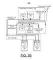
- FIGS. 1A and 1B are respective schematic and block diagram illustrating an exemplary circuit implementing an enhanced availability personality card in a chassis computer system in accordance with the preferred embodiments;
- FIG. 2 is a flow chart illustrating exemplary read operations performed by a chassis management module of the personality card of the circuit of FIG. 1 in accordance with the preferred embodiment
- FIG. 3 is a flow chart illustrating exemplary write operations performed by a chassis management module of the personality card of the circuit of FIG. 1 in accordance with the preferred embodiment
- FIGS. 4 and 5 illustrate a respective example chassis computer system for implementing an enhanced availability personality card in of the circuit of FIG. 1 in accordance with the preferred embodiment
- FIG. 6 is a flow diagram of a design process used in semiconductor design, manufacturing, and/or test.
- a circuit and method for implementing an enhanced availability personality card for a chassis computer system, and a design structure on which the subject circuit resides are provided.
- FIGS. 1A and 1B there is shown an example circuit generally designated by the reference character 100 for implementing an enhanced availability personality card for a chassis computer system in accordance with the preferred embodiments.
- the personality card circuit 100 supports chassis computer system including between multiple servers, and includes redundant components and paths enabling continued function with failure of any component.
- the personality card circuit 100 includes a personality card 102 connected by a first I2C bus A, 104 or primary I2C bus A, 104 , and a second I2C bus B, 104 or redundant I2C bus B, 104 via a midplane 106 of an associated chassis computer system to a pair of chassis management modules (CMM) A, B, 110 .
- chassis management modules (CMM) A, B, 110 includes a respective switch 112 connected to both the primary I2C bus A, 104 and the redundant I2C bus B, 104 .
- the personality card circuit 100 is located with the midplane 106 of a chassis computer system 400 and a chassis computer system 500 .
- Single-Points-of-Failure (SPOF) are eliminated from the personality card 102 and although the personality card 102 remains a Single-Point-of-Repair (SPOR) repairs are so infrequent ensuring very high availability of the personality card.
- SPOR Single-Point-of-Repair
- the personality card 102 and circuit 100 includes component redundancy and redundant paths so that any single component can fail and the personality card 102 continues to run unimpaired. Furthermore, if a circuit component fails, no visible alert is generated. Instead the circuit 100 and personality card 102 simply continue to function using the redundant paths to redundant components.
- the personality card 102 of circuit 100 includes a novel fail-in-place design.
- operation of the chassis computer system is continued using previously read data from the personality card 102 .
- the chassis computer system is scheduled to be taken down for a scheduled replacement of the personality card 102 only when both the first and second redundant critical components fail.
- the personality card 102 includes a pair of erasable programmable read only memories (EPROMs) A, B, 120 storing Vital Product Data (VPD) for the chassis computer system.
- Vital Product Data is a collection of configuration and informational data associated with a particular set of hardware or software.
- Vital product data stores information such as software version, details of the hardware configuration, levels of the hardware, part numbers, serial numbers, firmware and software component levels, and details of the server system configuration.
- Each of the EPROMs A, B, 120 is a type of non-volatile memory chip retaining its data when its power supply is turned off, and the data stored in the EPROM is erased with ultraviolet light.
- EPROM A, 120 is a primary device and the EPROM B, 120 provides a full mirror image of data stored on EPROM A, 120 .
- the personality card 102 includes a first temperature sensor A, 122 , and a second redundant temperature sensor B, 122 .
- the personality card 102 includes a first general purpose I/O (GPIO) A, 124 , and a second GPIO B, 124 .
- GPIO general purpose I/O
- Each of the components EPROMs A, B, 120 , temperature sensors A, B, 122 , and GPIOs A, B, 124 of the personality card 102 is connected to the respective independent I2C bus A, B, 104 .
- the redundant components and redundant paths provided by the respective independent I2C bus A, B, 104 eliminate the need for a multiplexer used with conventional personality card arrangements.
- the personality card circuit 100 includes redundant components and paths enabling continued function with failure of any component.
- the personality card circuit 100 eliminates critical SPOF (Single-Points-of-Failure) and although a SPOR (Single-Point-of-Repair) remains the need for a repair is virtually eliminated because the probability of both the first and second redundant component failing is so low over the useful life of the product to be virtually nonexistent providing very high availability.
- Each I2C bus A, B, 104 comprises an independent bidirectional bus or link providing multiple possible routing paths to each of the components EPROMs A, B, 120 ; temperature sensors A, B, 122 ; and GPIOs A, B, 124 via the respective CMM switch 112 connected both the primary I2C bus A, 104 and the redundant I2C bus B, 104 of the respective CMM A, B, 110 .
- the personality card 102 of the circuit 100 optionally includes a first personality card A, 130 , and a second personality card B, 130 .
- the first personality card A, 130 includes the first EPROM and the first temperature sensor and second personality card B, 130 includes the second EPROM and the second temperature sensor, eliminating Single-Points-of-Failure (SPOF) and ensuring very high availability of the personality card.
- SPOF Single-Points-of-Failure
- FIG. 2 there are shown exemplary read operations performed by a chassis management module 110 of the personality card 102 of the circuit 100 in accordance with the preferred embodiment starting at a block 200 .
- a block 202 it is determined if the CMM needs to read data or temperature from the personality card. If the CMM does not need to read data or temperature from the personality card as indicated at a decision block 204 , then the operations return to block 202 . Otherwise when determined the CMM needs to read data or temperature from the personality card at decision block 204 , then checking for successful read of EPROM A, 120 or temperature sensor A, 122 is performed as indicated at a block 206 .
- the CMM creates a personality card alert calling for a repair as indicated at a block 214 .
- the chassis continues to operate using data previously read from the personality card as indicated at a block 220 .
- the operations return to block 202 .
- FIG. 3 there are shown exemplary write operations performed by a chassis management module of the personality card 102 of the circuit 100 in accordance with the preferred embodiment starting at a block 300 .
- a block 302 it is determined if the CMM needs to turn on a chassis LED or write data to the personality card. If the CMM does not need to turn on a chassis LED or write data to the personality card as indicated at a decision block 304 , then the operations return to block 302 . If the CMM needs to turn on chassis LED, then the LED is turned on via the GPIO A, 124 or the GPIO B, 124 as indicated at a block 306 . If the CMM needs to write data to the personality card, then each of the EPROM A, 120 and EPROM B, 120 is written to make sure data is correctly written as indicated at a block 308 .
- the chassis When determined that the chassis is not to be taken down to replace the personality card 102 as indicated at a decision block 318 , then the chassis continues to operate using data previously read from the personality card as indicated at a block 320 . When determined that the chassis is scheduled to be taken down to replace the personality card 102 at decision block 318 , then the operations return to block 302 .
- FIGS. 4 and 5 there are shown a respective example chassis computer system for implementing an enhanced availability personality card 102 in of the circuit 100 of FIG. 1 respectively generally designated by the reference character 400 and 500 in accordance with the preferred embodiment.
- Each respective chassis computer system 400 and chassis computer system 500 includes the midplane 106 and the personality card 102 of circuit 100 of FIG. 1 .
- the chassis computer system 400 includes a plurality of multiple blade computers 402 that are coupled together by the midplane 106 and are capable of communicating with one another, as well as sharing common resources, such as storage devices, monitors, and input devices.
- Each of the multiple blades 402 is a pluggable board including at least one processor, on-board memory, and an Input/Output (I/O) interface.
- the computer system 400 includes a plurality of hot plug modules 404 and the multiple blade computers 402 received within a common center or chassis 410 .
- the chassis computer system 500 includes a plurality of hot plug modules 504 including a plurality of power supplies 506 and a plurality of fan packs 508 received within a chassis 510 .
- the chassis computer system 500 includes a shuttle 512 receiving the hot plug modules 504 and a pair of fan distribution cards 514 .
- the respective personality card 102 of circuit 100 of the chassis computer system 400 and the chassis computer system 500 is located with the midplane 106 within the respective chassis 410 , 510 .
- the respective personality card 102 which holds VPD associated with the chassis computer system 400 and the chassis computer system 500 includes the innovative fail-in-place design implemented for providing ultra high availability in accordance with the preferred embodiment.
- the personality card 102 is a small pluggable card received within the midplane 106 of the chassis computer system 500 .
- the personality card 102 is deliberately designed to not be hot swappable and is located within the respective chassis 410 , 510 so that it can not be easily moved because doing so could make it impossible for management software to accurately and uniquely identify a particular chassis computer system 400 or a particular chassis computer system 500 in a multiple chassis system.
- the failure of the personality card 102 does not cause an unscheduled outage of the chassis computer system 400 or the chassis computer system 500 .
- a personality card 102 fails, each of the chassis computer system 400 and the chassis computer system 500 continues to operate using previously read data from the personality card 102 .
- the chassis computer system 400 or the chassis computer system 500 is powered down for a scheduled replacement of the personality card 102 .
- FIG. 6 shows a block diagram of an example design flow 600 that may be used for circuit 100 described herein.
- Design flow 600 may vary depending on the type of circuit or IC being designed.
- a design flow 600 for building an application specific IC (ASIC) may differ from a design flow 600 for designing a standard component.
- Design structure 602 is preferably an input to a design process 604 and may come from an IP provider, a core developer, or other design company or may be generated by the operator of the design flow, or from other sources.
- Design structure 602 comprises circuits 102 , 200 in the form of schematics or HDL, a hardware-description language, for example, Verilog, VHDL, C, and the like.
- Design structure 602 may be contained on one or more non-transitory machine readable medium.
- design structure 602 may be a text file or a graphical representation of circuit 100 .
- Design process 604 preferably synthesizes, or translates, circuits 100 , 102 into a netlist 606 , where netlist 606 is, for example, a list of wires, transistors, logic gates, control circuits, I/O, models, etc. that describes the connections to other elements and circuits in an integrated circuit design and recorded on at least one of machine readable medium. This may be an iterative process in which netlist 606 is resynthesized one or more times depending on design specifications and parameters for the circuits.
- Design process 604 may include using a variety of inputs; for example, inputs from library elements 608 which may house a set of commonly used elements, circuits, and devices, including models, layouts, and symbolic representations, for a given manufacturing technology, such as different technology nodes, 32 nm, 45 nm, 90 nm, and the like, design specifications 610 , characterization data 612 , verification data 614 , design rules 616 , and test data files 618 , which may include test patterns and other testing information. Design process 604 may further include, for example, standard circuit design processes such as timing analysis, verification, design rule checking, place and route operations, and the like.
- standard circuit design processes such as timing analysis, verification, design rule checking, place and route operations, and the like.
- Design process 604 preferably translates an embodiment of the invention as shown in FIGS. 1A , 1 B, 2 , 3 , and 5 along with any additional integrated circuit design or data (if applicable), into a second design structure 620 .
- Design structure 620 resides on a storage medium in a data format used for the exchange of layout data of integrated circuits, for example, information stored in a GDSII (GDS2), GL1, OASIS, or any other suitable format for storing such design structures.
- Design structure 620 may comprise information such as, for example, test data files, design content files, manufacturing data, layout parameters, wires, levels of metal, vias, shapes, data for routing through the manufacturing line, and any other data required by a semiconductor manufacturer to produce an embodiment of the invention as shown in FIGS.
- Design structure 620 may then proceed to a stage 622 where, for example, design structure 620 proceeds to tape-out, is released to manufacturing, is released to a mask house, is sent to another design house, is sent back to the customer, and the like.
Landscapes
- Engineering & Computer Science (AREA)
- Theoretical Computer Science (AREA)
- Quality & Reliability (AREA)
- Physics & Mathematics (AREA)
- General Engineering & Computer Science (AREA)
- General Physics & Mathematics (AREA)
- Hardware Redundancy (AREA)
Abstract
Description
Claims (20)
Priority Applications (1)
| Application Number | Priority Date | Filing Date | Title |
|---|---|---|---|
| US13/291,874 US8635488B2 (en) | 2011-11-08 | 2011-11-08 | Implementing ultra high availability personality card |
Applications Claiming Priority (1)
| Application Number | Priority Date | Filing Date | Title |
|---|---|---|---|
| US13/291,874 US8635488B2 (en) | 2011-11-08 | 2011-11-08 | Implementing ultra high availability personality card |
Publications (2)
| Publication Number | Publication Date |
|---|---|
| US20130117601A1 US20130117601A1 (en) | 2013-05-09 |
| US8635488B2 true US8635488B2 (en) | 2014-01-21 |
Family
ID=48224576
Family Applications (1)
| Application Number | Title | Priority Date | Filing Date |
|---|---|---|---|
| US13/291,874 Active 2032-06-14 US8635488B2 (en) | 2011-11-08 | 2011-11-08 | Implementing ultra high availability personality card |
Country Status (1)
| Country | Link |
|---|---|
| US (1) | US8635488B2 (en) |
Families Citing this family (6)
| Publication number | Priority date | Publication date | Assignee | Title |
|---|---|---|---|---|
| US12561270B2 (en) | 2016-07-26 | 2026-02-24 | Samsung Electronics Co., Ltd. | Self-configuring SSD multi-protocol support in host-less environment |
| US11461258B2 (en) * | 2016-09-14 | 2022-10-04 | Samsung Electronics Co., Ltd. | Self-configuring baseboard management controller (BMC) |
| US12541480B2 (en) | 2016-07-26 | 2026-02-03 | Samsung Electronics Co., Ltd. | Self-configuring SSD multi-protocol support in host-less environment |
| US10210123B2 (en) | 2016-07-26 | 2019-02-19 | Samsung Electronics Co., Ltd. | System and method for supporting multi-path and/or multi-mode NMVe over fabrics devices |
| US12556417B2 (en) | 2016-07-26 | 2026-02-17 | Samsung Electronics Co., Ltd. | Modular system (switch boards and mid-plane) for supporting 50G or 100G ethernet speeds of FPGA+SSD |
| CN110162430B (en) * | 2018-02-13 | 2021-11-09 | 华为技术有限公司 | Temperature self-adaption method, device and equipment |
Citations (4)
| Publication number | Priority date | Publication date | Assignee | Title |
|---|---|---|---|---|
| US20050097255A1 (en) * | 2003-10-30 | 2005-05-05 | International Business Machines Corporation | I2C device including bus switches and programmable address |
| US20070174517A1 (en) * | 2006-01-03 | 2007-07-26 | Robillard Michael N | Managing management controller communications |
| US7757123B1 (en) * | 2006-06-29 | 2010-07-13 | Emc Corporation | Managing faults |
| US20130067134A1 (en) * | 2011-09-13 | 2013-03-14 | International Business Machines Corporation | Pseudo multi-master i2c operation in a blade server chassis |
-
2011
- 2011-11-08 US US13/291,874 patent/US8635488B2/en active Active
Patent Citations (4)
| Publication number | Priority date | Publication date | Assignee | Title |
|---|---|---|---|---|
| US20050097255A1 (en) * | 2003-10-30 | 2005-05-05 | International Business Machines Corporation | I2C device including bus switches and programmable address |
| US20070174517A1 (en) * | 2006-01-03 | 2007-07-26 | Robillard Michael N | Managing management controller communications |
| US7757123B1 (en) * | 2006-06-29 | 2010-07-13 | Emc Corporation | Managing faults |
| US20130067134A1 (en) * | 2011-09-13 | 2013-03-14 | International Business Machines Corporation | Pseudo multi-master i2c operation in a blade server chassis |
Also Published As
| Publication number | Publication date |
|---|---|
| US20130117601A1 (en) | 2013-05-09 |
Similar Documents
| Publication | Publication Date | Title |
|---|---|---|
| US8635488B2 (en) | Implementing ultra high availability personality card | |
| US7698594B2 (en) | Reconfigurable processor and reconfiguration method executed by the reconfigurable processor | |
| US10846159B2 (en) | System and method for managing, resetting and diagnosing failures of a device management bus | |
| US12050508B2 (en) | Data processing system and operating method thereof | |
| CN103853678A (en) | Board management device and board management system and control card using same | |
| CN113821091A (en) | Fan fault compensation | |
| EP3848807A1 (en) | Data processing system and method for configuring and operating a data processing system | |
| US8612656B2 (en) | Implementing device physical location identification in serial attached SCSI (SAS) fabric using resource path groups | |
| US7882479B2 (en) | Method and apparatus for implementing redundant memory access using multiple controllers on the same bank of memory | |
| KR20060047693A (en) | System and method of scsi and sas hardware validation | |
| CN103475514B (en) | Node, group system and BIOS without BMC repair and upgrade method | |
| US12359981B2 (en) | Systems and methods for effective reading of multiple temperature sensors on memory modules | |
| US8374046B2 (en) | Computing device and method for clearing data stored in complementary metal-oxide semiconductor chip | |
| US20170309570A1 (en) | Reconfigurable repeater system | |
| US20070028204A1 (en) | Method and program for high-level synthesis, and method for verifying a gate network list using the high-level synthesis method | |
| CN113535494A (en) | Equipment debugging method and electronic equipment | |
| US20190108105A1 (en) | Semiconductor system including fault manager | |
| WO2016127578A1 (en) | Processor sub-card, power board adapted to processor sub-card, and system board | |
| US8725483B2 (en) | Minimizing the maximum required link capacity for three-dimensional interconnect routing | |
| CN119862112A (en) | Automated testing for checking user interface cutoffs | |
| US11544129B2 (en) | Cross-component health monitoring and improved repair for self-healing platforms | |
| JP2013200616A (en) | Information processor and restoration circuit of information processor | |
| JP2008204335A (en) | Semiconductor storage device | |
| JP5561790B2 (en) | Hardware failure suspect identification device, hardware failure suspect identification method, and program | |
| CN113851181A (en) | Apparatus, system, and method for repairing memory with multi-cell switching |
Legal Events
| Date | Code | Title | Description |
|---|---|---|---|
| AS | Assignment |
Owner name: INTERNATIONAL BUSINESS MACHINES CORPORATION, NEW Y Free format text: ASSIGNMENT OF ASSIGNORS INTEREST;ASSIGNORS:ACKARET, JERRY D.;BANDHOLZ, JUSTIN P.;BIGELOW, BRIAN E.;AND OTHERS;SIGNING DATES FROM 20111031 TO 20111107;REEL/FRAME:027194/0831 |
|
| STCF | Information on status: patent grant |
Free format text: PATENTED CASE |
|
| AS | Assignment |
Owner name: LENOVO INTERNATIONAL LIMITED, HONG KONG Free format text: ASSIGNMENT OF ASSIGNORS INTEREST;ASSIGNOR:INTERNATIONAL BUSINESS MACHINES CORPORATION;REEL/FRAME:034194/0291 Effective date: 20140926 |
|
| FPAY | Fee payment |
Year of fee payment: 4 |
|
| MAFP | Maintenance fee payment |
Free format text: PAYMENT OF MAINTENANCE FEE, 8TH YEAR, LARGE ENTITY (ORIGINAL EVENT CODE: M1552); ENTITY STATUS OF PATENT OWNER: LARGE ENTITY Year of fee payment: 8 |
|
| MAFP | Maintenance fee payment |
Free format text: PAYMENT OF MAINTENANCE FEE, 12TH YEAR, LARGE ENTITY (ORIGINAL EVENT CODE: M1553); ENTITY STATUS OF PATENT OWNER: LARGE ENTITY Year of fee payment: 12 |