US8632736B2 - Float and tube system for separating a suspension with an internal trap - Google Patents
Float and tube system for separating a suspension with an internal trap Download PDFInfo
- Publication number
- US8632736B2 US8632736B2 US13/735,410 US201313735410A US8632736B2 US 8632736 B2 US8632736 B2 US 8632736B2 US 201313735410 A US201313735410 A US 201313735410A US 8632736 B2 US8632736 B2 US 8632736B2
- Authority
- US
- United States
- Prior art keywords
- float
- slide
- compartment
- target analyte
- main body
- Prior art date
- Legal status (The legal status is an assumption and is not a legal conclusion. Google has not performed a legal analysis and makes no representation as to the accuracy of the status listed.)
- Active
Links
Images


Classifications
-
- B—PERFORMING OPERATIONS; TRANSPORTING
- B04—CENTRIFUGAL APPARATUS OR MACHINES FOR CARRYING-OUT PHYSICAL OR CHEMICAL PROCESSES
- B04B—CENTRIFUGES
- B04B7/00—Elements of centrifuges
-
- B—PERFORMING OPERATIONS; TRANSPORTING
- B01—PHYSICAL OR CHEMICAL PROCESSES OR APPARATUS IN GENERAL
- B01L—CHEMICAL OR PHYSICAL LABORATORY APPARATUS FOR GENERAL USE
- B01L3/00—Containers or dishes for laboratory use, e.g. laboratory glassware; Droppers
- B01L3/50—Containers for the purpose of retaining a material to be analysed, e.g. test tubes
- B01L3/502—Containers for the purpose of retaining a material to be analysed, e.g. test tubes with fluid transport, e.g. in multi-compartment structures
- B01L3/5021—Test tubes specially adapted for centrifugation purposes
- B01L3/50215—Test tubes specially adapted for centrifugation purposes using a float to separate phases
-
- G—PHYSICS
- G01—MEASURING; TESTING
- G01N—INVESTIGATING OR ANALYSING MATERIALS BY DETERMINING THEIR CHEMICAL OR PHYSICAL PROPERTIES
- G01N33/00—Investigating or analysing materials by specific methods not covered by groups G01N1/00 - G01N31/00
- G01N33/48—Biological material, e.g. blood, urine; Haemocytometers
- G01N33/483—Physical analysis of biological material
- G01N33/487—Physical analysis of biological material of liquid biological material
- G01N33/49—Blood
- G01N33/491—Blood by separating the blood components
-
- B—PERFORMING OPERATIONS; TRANSPORTING
- B01—PHYSICAL OR CHEMICAL PROCESSES OR APPARATUS IN GENERAL
- B01L—CHEMICAL OR PHYSICAL LABORATORY APPARATUS FOR GENERAL USE
- B01L2200/00—Solutions for specific problems relating to chemical or physical laboratory apparatus
- B01L2200/02—Adapting objects or devices to another
- B01L2200/025—Align devices or objects to ensure defined positions relative to each other
-
- Y—GENERAL TAGGING OF NEW TECHNOLOGICAL DEVELOPMENTS; GENERAL TAGGING OF CROSS-SECTIONAL TECHNOLOGIES SPANNING OVER SEVERAL SECTIONS OF THE IPC; TECHNICAL SUBJECTS COVERED BY FORMER USPC CROSS-REFERENCE ART COLLECTIONS [XRACs] AND DIGESTS
- Y10—TECHNICAL SUBJECTS COVERED BY FORMER USPC
- Y10T—TECHNICAL SUBJECTS COVERED BY FORMER US CLASSIFICATION
- Y10T137/00—Fluid handling
- Y10T137/7287—Liquid level responsive or maintaining systems
- Y10T137/7358—By float controlled valve
-
- Y—GENERAL TAGGING OF NEW TECHNOLOGICAL DEVELOPMENTS; GENERAL TAGGING OF CROSS-SECTIONAL TECHNOLOGIES SPANNING OVER SEVERAL SECTIONS OF THE IPC; TECHNICAL SUBJECTS COVERED BY FORMER USPC CROSS-REFERENCE ART COLLECTIONS [XRACs] AND DIGESTS
- Y10—TECHNICAL SUBJECTS COVERED BY FORMER USPC
- Y10T—TECHNICAL SUBJECTS COVERED BY FORMER US CLASSIFICATION
- Y10T436/00—Chemistry: analytical and immunological testing
- Y10T436/25—Chemistry: analytical and immunological testing including sample preparation
- Y10T436/25375—Liberation or purification of sample or separation of material from a sample [e.g., filtering, centrifuging, etc.]
Definitions
- This disclosure relates generally to density-based fluid separation and, in particular, to tube and float systems for the separation of constituent suspension components layered by centrifugation.
- Suspensions often include materials of interest that are difficult to detect, extract and isolate for analysis.
- whole blood is a suspension of materials in a fluid.
- the materials include billions of red and white blood cells and platelets in a proteinaceous fluid called plasma.
- Whole blood is routinely examined for the presence of abnormal organisms or cells, such as fetal cells, endothelial cells, epithelial cells, parasites, bacteria, and inflammatory cells, and viruses, including HIV, cytomegalovirus, hepatitis C virus, and Epstein-Barr virus and nucleic acids.
- Typical techniques used to analyze a blood sample include the steps of smearing a film of blood on a slide 214 and staining the film in a way that enables certain components to be examined by bright field microscopy.
- CTCs circulating tumor cells
- CTCs circulating tumor cells
- the ability to accurately detect and analyze CTCs is of particular interest to oncologists and cancer researchers, but CTCs occur in very low numbers in peripheral whole blood samples. For instance, a 7.5 ml sample of peripheral whole blood that contains as few as 3 CTCs is considered clinically relevant in the diagnosis and treatment of a cancer patient.
- detecting even 1 CTC in a 7.5 ml blood sample may be clinically relevant and is equivalent to detecting 1 CTC in a background of about 40-50 billion red and white blood cells.
- Using existing techniques to find, isolate and extract as few as 3 CTCs of a whole blood sample is extremely time consuming, costly and is extremely difficult to accomplish.
- FIGS. 1A-1B show isometric views of two example tube and float systems.
- FIGS. 2A-2C show an example of a float.
- FIG. 2D-2F examples of floats.
- FIGS. 3-6 show examples of floats with different structural elements.
- FIG. 7A-7C show an example of a float.
- FIG. 8A shows an example float used to trap a target analyte.
- FIG. 8B shows an example float used to trap a target analyte.
- This disclosure is directed to systems for separating a target analyte from a suspension.
- a suspension is added to a tube.
- a float is also added to the tube, and the tube, float, and suspension are centrifuged together, causing the constituent components of the suspension to separate into different layers along the axial length of the tube according to their specific gravities.
- the float has a specific gravity that positions the float at approximately the same level as a layer containing the target analyte, when the tube, float and sample are centrifuged.
- the material Prior to isolation, the material may be located between an outer surface of the float and an inner surface of the tube, or within a central bore that extends longitudinally through the float.
- the target analyte may then be drawn into a compartment within the float, thereby isolating the target analyte from the other suspension constituents.
- a general description of tube and float systems is provided in a first subsection.
- Methods for using tube and float systems are provided in a second subsection.
- FIG. 1A shows an isometric view of an example tube and float system 100 .
- the system 100 includes a tube 102 and a float 104 suspended within a suspension 106 .
- the tube 102 has a circular cross-section, a first closed end 108 , and a second open end 110 .
- the open end 110 is sized to receive a stopper or cap 112 .
- the tube may also have two open ends that are sized to receive stoppers or caps, such as the example tube and float system 120 shown FIG. 1B .
- the system 120 is similar to the system 100 except the tube 102 is replaced by a tube 122 that includes two open ends 124 and 126 configured to receive the cap 112 and a cap 128 , respectively.
- the tubes 102 and 122 have a generally cylindrical geometry, but may also have a tapered geometry that widens, narrows, or a combination thereof toward the open ends 110 and 124 , respectively.
- the tubes 102 and 122 have a circular cross-section, in other embodiments, the tubes 102 and 122 can have elliptical, square, triangular, rectangular, octagonal, or any other suitable cross-sectional shape that substantially extends the length of the tube.
- the tubes 102 and 122 can be composed of a transparent or semitransparent flexible material, such as flexible plastic or another suitable material.
- the tube may also include a plug (not shown) at the closed end 108 to permit the removal of a fluid, the suspension, or a suspension fraction, whether with a syringe, a pump, by draining, or the like.
- the tube may be rigid or flexible and the float may be rigid or flexible.
- the float 104 can be captured within the tube 102 by an interference fit.
- the expandable sidewall can be expanded radially to a larger diameter by applying an axial load, such as axial pressure due to centrifugation, an axial force produced by a clamp, external vacuum, or internally-introduced pressure.
- the larger diameter is sufficiently large to permit axial movement of the float 104 in the tube 102 during centrifugation.
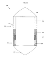
- FIG. 2A shows an isometric view of the float 104 shown in FIG. 1 .
- the float 104 includes a main body, including a solid portion 202 and a permeable portion 204 , two teardrop-shaped end caps 206 and 208 , and raised structural elements 210 radially spaced and axially oriented on the main body.
- the permeable portion 204 includes holes 212 to permit the passage of the target analyte from the separate suspension into float 104 .
- the float 104 can also include two dome-shaped end caps, two cone-shaped end caps, or the end caps can have any appropriate shape or geometry.
- the raised structural elements 210 extend outward from the main body to engage the inner wall of the tube 102 .
- the solid portion 202 of the main body prevents fluids, materials, or the like from passing into or out of the float 104 .
- the permeable portion 204 of the main body permits the passage of fluids, materials, or the like into and out of the float 104 .
- the two teardrop-shaped caps 206 and 208 may be removable from the main body.
- the float 104 has a density substantially the same as the density of the target analyte.
- FIG. 2B shows a cross-section of the float 104 taken along a line I-I in which a slide 214 , in a closed position, blocks passage of a target analyte through the permeable portion 204 of the main body.
- FIG. 2C shows a cross-section of the float 104 taken along the line I-I in which the slide 214 , in an open position, permits the passage of a target analyte through the permeable portion 204 of the main body.
- the main body further comprises a float compartment 218 , the slide 214 , and a catch 216 .
- the permeable portion 204 of the main body is in fluid communication with the float compartment 218 , so as to permit a target analyte to pass into the float compartment 218 through the permeable portion 204 .
- the slide 214 is configured to block the passage of materials into the float compartment 218 when the slide 214 is in a closed position.
- the slide 214 includes a slide groove 220 to engage the catch 216 of the main body.
- the slide groove 220 engages the catch 216 of the main body to allow the slide 214 to slide within the main body while preventing the slide 214 from detaching or separating from the main body.
- the slide 214 has an outer diameter, an inner diameter, and a groove diameter. The groove diameter is less than or equal to the outer diameter; and the groove diameter is greater than the inner diameter.
- the slide 214 may have a density greater than or less than the density of the main body of the float 104 . By having different densities, the slide 214 may remain in a closed position during centrifugation and then may move into an open position after centrifugation. When the slide 214 is less dense than the main body, the permeable portion may be in a higher location on the main body, as the slide 214 may rise within the main body during centrifugation. Alternatively, when the slide 214 is denser than the main body, the permeable portion may be in a lower location on the main body, as the slide 214 may drop within the main body during centrifugation.
- FIG. 2D shows a cross-section of the float 104 taken along the line I-I with a permeable portion 204 that is selectively permeable.
- the permeable portion 204 of the main body may be selectively permeable.
- the permeable portion 204 may comprise layers 228 - 230 , as seen in magnified view 240 , wherein each layer 228 - 230 includes holes 232 - 234 and the holes of each layer are bound with a specific type of attachment particle 236 - 238 , such as an antibody.
- Each layer 228 - 230 may be configured to hold a non-target analyte 224 - 226 , while permitting the passage of other analytes.
- the permeable portion 204 may be fowled from three layers 228 - 230 , each layer including holes that are sized to be larger than the target analyte 222 .
- the outer layer 228 may be bound with antibodies to hold endothelial cells; the middle layer 229 may be bound with antibodies to hold epithelial cells; and the inner layer 230 may be bound with antibodies to hold mesenchymal cells.
- the target analyte 222 passes through the layers 228 - 230 and into the float 104 ; whereas the epithelial, endothelial, and mesenchymal cells are held by the appropriate layer, thereby preventing those cells from passing into the float 104 .
- FIG. 2E shows a float 250 attached to a suction device 256 via a conduit 254 .
- FIG. 2F shows a cross-section of the float 250 along a line II-II.
- the float 250 is similar to float 104 , except that float 240 includes an adapter 252 .
- the adapter 252 is in fluid communication with the float compartment 218 , such that a pressure differential may be applied within the float compartment 218 after centrifugation by connecting the suction device 256 to the adapter 252 via the conduit 254 .
- the suction device 256 such as a vacuum pump or a syringe, is configured to apply the pressure differential, such that a target analyte may be drawn into the float compartment 218 .
- the number of raised structural elements, raised structural element spacing, and raised structural element thickness can each be independently varied.
- the raised structural elements 210 can also be broken or segmented.
- the main body is sized to have an outer diameter that is less than the inner diameter of the tube 102 , thereby defining fluid retention channels between the outer surface of the main body and the inner wall of the tube 102 .
- the surfaces of the main body between the raised structural elements 210 can be flat, curved or have another suitable geometry.
- the raised structural elements 210 and the main body 202 form a single structure.
- Embodiments include other types of geometric shapes for end caps.
- FIG. 3 shows an isometric view of an example float 300 with a dome-shaped end cap 306 and a cone-shaped end cap 308 .
- a main body 306 of the float 300 can include the same solid portion 302 of the main body, the same permeable portion 304 of the main body, and the same raised structural elements 310 as the float 104 .
- a float can also include a teardrop-shaped end cap.
- the float end caps can include other geometric shapes and are not intended to be limited to the shapes described herein.
- the main body of the float 104 can include a variety of different raised structural elements for separating immunotherapeutic materials, supporting the tube wall, or directing the suspension fluid around the float during centrifugation.
- FIGS. 4 , 5 , and 6 show examples of different types of raised structural elements. Embodiments are not intended to be limited to these examples.
- a main body of a float 400 is similar to the float 104 except the main body includes a number of protrusions 410 that provide support for the tube. In alternative embodiments, the number and pattern of protrusions can be varied.
- FIG. 4 a main body of a float 400 is similar to the float 104 except the main body includes a number of protrusions 410 that provide support for the tube. In alternative embodiments, the number and pattern of protrusions can be varied.
- FIG. 4 a main body of a float 400 is similar to the float 104 except the main body includes a number of protrusions 410 that provide support for the tube. In
- a main body of a float 500 includes a single continuous helical structure or ridge 512 that spirals around the main body creating a helical channel 510 .
- the helical ridge 512 can be rounded or broken or segmented to allow fluid to flow between adjacent turns of the helical ridge 512 .
- the helical ridge spacing and rib thickness can be independently varied.
- a main body of a float 600 includes raised structural elements 610 extending circumferentially around the main body. One of the raised structural elements 610 can be omitted.
- the float 600 including the circumferentially-extending raised structural elements 610 , may also include alternative raised structural elements (not shown) on the main body.
- the alternative raised structural element (not shown) may be vertical, horizontal, or at least one helical ridge that spiral around the main body, or any appropriate raised structural element shape or configuration, as discussed above.
- FIG. 7A shows an exploded view of a float 700 .
- FIG. 7B shows a cross-section of the float 700 taken along a line in which a slide 704 , in a closed position, blocks passage of a target analyte through the permeable portion 712 of the main body.
- FIG. 7C shows a cross-section of the float 700 taken along the line in which the slide 704 , in an open position, permits the passage of a target analyte through the permeable portion 712 of the main body.
- the float 700 is similar to float 104 , except that float 700 may not include support members, and the suspension and the suspension components are forced into a fluid passageway 720 , the fluid passageway 720 being a bore that extends longitudinally through a cap 702 and the main body 706 .
- the fluid passageway 720 includes a permeable portion 712 , which includes holes 714 .
- the main body 706 may include a bottom end having a concavity to force the suspension and suspension components into the fluid passageway 720 during and/or after centrifugation.
- the concavity may be conical or hemispherical.
- the float 700 may also include the cap 702 having a concavity to force the suspension and suspension components into the fluid passageway 720 during and/or after centrifugation.
- the concavity may be conical or hemispherical.
- the slide 704 includes a slide groove 708 .
- the float can be composed of a variety of different materials.
- the float can be composed of a metal, including, but not limited to, aluminum, brass, gold, silver, tin, copper, bronze, chromium, cobalt, nickel, lead, iron, steel, manganese, zinc, neodymium, and combinations thereof.
- the float can be composed of a organic or inorganic materials; ferrous plastics; sintered metal; machined metal; and plastic materials, such as polyoxymethylene (“Delrin®”), polystyrene, acrylonitrile butadiene styrene (“ABS”) copolymers, aromatic polycarbonates, aromatic polyesters, carboxymethylcellulose, ethyl cellulose, ethylene vinyl acetate copolymers, nylon, polyacetals, polyacetates, polyacrylonitrile and other nitrile resins, polyacrylonitrile-vinyl chloride copolymer, polyamides, aromatic polyamides (“aramids”), polyamide-imide, polyarylates, polyarylene oxides, polyarylene sulfides, polyarylsulfones, polybenzimidazole, polybutylene terephthalate, polycarbonates, polyester, polyester imides, polyether sulfones, polyetherimides, polyetherketones, polyetheretherketone
- a sample suspension can be urine, blood, bone marrow, cystic fluid, ascites fluid, stool, semen, cerebrospinal fluid, nipple aspirate fluid, saliva, amniotic fluid, vaginal secretions, mucus membrane secretions, aqueous humor, vitreous humor, vomit, and any other physiological fluid or semi-solid.
- a disease-carrying analyte can be a cell, such as ova or a circulating tumor cell (“CTC”), a circulating endothelial cell, a vesicle, a liposome, a protein, a nucleic acid, a biological molecule, a naturally occurring or artificially prepared microscopic unit having an enclosed membrane, parasites, microorganisms, viruses, or inflammatory cells.
- CTC circulating tumor cell
- a suspension is transferred to the tube of a tube and float system, such as the tube and float systems 100 and 120 shown in FIG. 1 .
- a float is added to the tube and the cap is attached to seal the open end of the tube.
- the tube, float, and suspension are centrifuged for a period of time sufficient to allow separation of particles suspended in the suspension according to their specific gravities.
- the float has been selected with a density that positions the float 104 at approximately the same level as the target analyte within the tube.
- the slide 214 is then moved from a closed position to an open position, thereby exposing the holes of the permeable portion 204 , to permit passage of the target analyte into the float compartment.
- pressure gradient such as by a vacuum
- the vacuum may be created within the float compartment 218 of the main body prior to centrifugation.
- the slide, prior to and during centrifugation remains in a closed position due an outside force or mechanism or due to the density of the slide 214 being equal to or greater than the main body.
- the target analyte will settle in the fluid passageway of the main body, as it will have a density equal to that of the float.
- the slide 214 may be moved into the open position. The slide 214 may be moved from the closed position to the open position using an outside force or mechanism.
- the outside force or mechanism may include a magnet embedded in the slide 214 and then using a separate magnet to move the slide 214 to the open position; the slide 214 may further comprise a shaft extending through a portion of the teardrop-shaped cap which an operator may grab and pull to move the slide 214 into the open position; there may be a release which holds the slide 214 down (the slide 214 being held down by a separate force such as that caused by a spring, the release itself, or pressure) and then will be removed, thereby causing the slide 214 to move into the open position; or gravity may cause the slide 214 to move, due to the difference in densities between the slide 214 and the main body.
- the release may be on the outside of the main body such that contact by the release with the tube will cause the slide 214 to move into the open position; the release may be located anywhere on the float so that the slide 214 may be released and moved into the open position.
- one of the caps 206 and 208 may include an adapter (not shown) that is in fluid communication with the float compartment 218 .
- a conduit such as a hose or tubing
- the hose or tubing is then connected to a pump, syringe, or the like, to cause a pressure differential, suction, or the like within the float compartment 218 , thereby drawing the target analyte 804 into the float compartment 218 .
- FIG. 8A shows a first example suspension composed of a sample of anticoagulated whole blood combined with the sample separated into a plasma layer 801 , a Buffy coat layer 802 , and a red blood cell layer 803 .
- the float 104 spreads the Buffy coat 802 between the main body of the float 104 and inner wall of the tube 102 with red blood cells 803 packed below the Buffy coat 802 and the plasma 801 located above the Buffy coat 802 .
- a slide (not shown) is moved from a closed position, thereby preventing materials from entering a float compartment 218 , to an open position, thereby making the float compartment 218 accessible to a target analyte 804 via holes 212 .
- the magnified view 806 depicts the target analyte 804 being drawn into the float compartment 218 through holes 212 of a permeable portion 204 of the main body.
- FIG. 8B shows the first example suspension composed of a sample of anticoagulated whole blood combined with the sample separated into the plasma layer 801 , the Buffy coat layer 802 , and the red blood cell layer 803 .
- a float 700 forces the Buffy coat 802 into a fluid passageway 718 with red blood cells 803 packed below the Buffy coat 802 and the plasma 801 located above the Buffy coat 802 .
- a slide (not shown) is moved from a closed position, thereby preventing materials from entering a float compartment 720 , to an open position, thereby making the float compartment 720 accessible to the target analyte 804 via holes 714 .
- the magnified view 808 is a cross-section of the system taken along a line IV-IV. The magnified view 808 depicts the target analyte 804 being drawn into the float compartment 720 through holes 714 of a permeable portion 712 of the main body.
- the float may be removed from the tube. After the float has been removed from the tube, one of the caps 206 and 208 may then be removed from the main body, such that the target analyte is now accessible.
- the target analyte may then be analyzed using any appropriate analysis method or technique, though more specifically intracellular analysis including intracellular or extracellular protein labeling; nucleic acid analysis, including, but not limited to, nucleic acid microarrays; protein microarrays; fluorescent in situ hybridization (“FISH”—a tool for analyzing DNA and/or RNA, such as gene copy number changes); or branched DNA (“bDNA”—a tool for analyzing DNA and/or RNA, such as mRNA expression levels) analysis.
- FISH fluorescent in situ hybridization
- bDNA branched DNA
- intracellular proteins which may be labeled include, but are not limited to, cytokeratin (“CK”), actin, Arp2/3, coronin, dystrophin, FtsZ, myosin, spectrin, tubulin, collagen, cathepsin D, ALDH, PBGD, Akt1, Akt2, c-myc, caspases, survivin, p27 kip , FOXC2, BRAF, Phospho-Akt1 and 2, Phospho-Erk1/2, Erk1/2, P38 MAPK, Vimentin, ER, PgR, PI3K, pFAK, KRAS, ALKH1, Twist1, Snail1, ZEB1, Slug, Ki-67, M30, MAGEA3, phosphorylated receptor kinases, modified histones, chromatin-associated proteins, and MAGE.
- CK cytokeratin
- actin actin
- Arp2/3, coronin coronin
- dystrophin FtsZ
- fixing agents such as formaldehyde, formalin, methanol, acetone, paraformaldehyde, or glutaraldehyde
- detergents such as saponin, polyoxyethylene, digitonin, octyl ⁇ -glucoside, octyl ⁇ -thioglucoside, 1-S-octyl- ⁇ -D-thioglucopyranoside, polysorbate-20, CHAPS, CHAPSO, (1,1,3,3-Tetramethylbutyl)phenyl-polyethylene glycol or octylphenol ethylene oxide
- labeling agents such as fluorescently-labeled antibodies, Pap stain, Giemsa stain, or hematoxylin and eosin stain may be used.
Landscapes
- Health & Medical Sciences (AREA)
- Life Sciences & Earth Sciences (AREA)
- Engineering & Computer Science (AREA)
- Chemical & Material Sciences (AREA)
- Hematology (AREA)
- Biomedical Technology (AREA)
- Analytical Chemistry (AREA)
- General Health & Medical Sciences (AREA)
- Physics & Mathematics (AREA)
- Clinical Laboratory Science (AREA)
- Ecology (AREA)
- Chemical Kinetics & Catalysis (AREA)
- Biophysics (AREA)
- Molecular Biology (AREA)
- Urology & Nephrology (AREA)
- Food Science & Technology (AREA)
- Medicinal Chemistry (AREA)
- Biochemistry (AREA)
- General Physics & Mathematics (AREA)
- Immunology (AREA)
- Pathology (AREA)
- Sampling And Sample Adjustment (AREA)
Abstract
Description
Claims (20)
Priority Applications (1)
| Application Number | Priority Date | Filing Date | Title |
|---|---|---|---|
| US13/735,410 US8632736B2 (en) | 2012-01-06 | 2013-01-07 | Float and tube system for separating a suspension with an internal trap |
Applications Claiming Priority (2)
| Application Number | Priority Date | Filing Date | Title |
|---|---|---|---|
| US201261583866P | 2012-01-06 | 2012-01-06 | |
| US13/735,410 US8632736B2 (en) | 2012-01-06 | 2013-01-07 | Float and tube system for separating a suspension with an internal trap |
Publications (2)
| Publication Number | Publication Date |
|---|---|
| US20130189168A1 US20130189168A1 (en) | 2013-07-25 |
| US8632736B2 true US8632736B2 (en) | 2014-01-21 |
Family
ID=48745482
Family Applications (1)
| Application Number | Title | Priority Date | Filing Date |
|---|---|---|---|
| US13/735,410 Active US8632736B2 (en) | 2012-01-06 | 2013-01-07 | Float and tube system for separating a suspension with an internal trap |
Country Status (2)
| Country | Link |
|---|---|
| US (1) | US8632736B2 (en) |
| WO (1) | WO2013103982A1 (en) |
Cited By (6)
| Publication number | Priority date | Publication date | Assignee | Title |
|---|---|---|---|---|
| US11278884B2 (en) | 2014-10-28 | 2022-03-22 | Arteriocyte Medical Systems, Inc. | Centrifuge tube comprising a floating buoy, and methods for using the same |
| US11478787B2 (en) | 2018-07-09 | 2022-10-25 | Hanuman Pelican, Inc. | Apparatus and methods for separating blood components |
| US11534533B2 (en) | 2018-07-09 | 2022-12-27 | Hanuman Pelican, Inc. | Apparatus and methods for processing blood |
| US11559613B2 (en) | 2019-02-06 | 2023-01-24 | Hanuman Pelican, Inc. | Apparatus and methods for concentrating platelet-rich plasma |
| US11654428B2 (en) | 2019-01-21 | 2023-05-23 | Vias Partners, Llc | Methods, systems and apparatus for separating components of a biological sample |
| US12007382B2 (en) | 2019-10-31 | 2024-06-11 | Crown Laboratories, Inc. | Systems, methods and apparatus for separating components of a sample |
Families Citing this family (2)
| Publication number | Priority date | Publication date | Assignee | Title |
|---|---|---|---|---|
| CN103956939B (en) * | 2014-04-30 | 2016-03-02 | 西北工业大学 | For the composite control method of the array electromagnetism-permanent magnet system of space microgravity ground simulation |
| CN110954359B (en) * | 2019-05-07 | 2022-04-08 | 河海大学 | An automatic water sample collection device with freely controllable water depth |
Citations (15)
| Publication number | Priority date | Publication date | Assignee | Title |
|---|---|---|---|---|
| US5496704A (en) | 1991-10-28 | 1996-03-05 | Fiedler; Paul | Method for in vitro detection of formed elements in biological samples |
| US5736033A (en) * | 1995-12-13 | 1998-04-07 | Coleman; Charles M. | Separator float for blood collection tubes with water swellable material |
| US6197523B1 (en) | 1997-11-24 | 2001-03-06 | Robert A. Levine | Method for the detection, identification, enumeration and confirmation of circulating cancer and/or hematologic progenitor cells in whole blood |
| US6444436B1 (en) | 2000-02-22 | 2002-09-03 | David L. Rimm | Evacuated container assembly for analysis of a blood sample for the presence or absence of rare events |
| US6670197B2 (en) | 1997-11-24 | 2003-12-30 | David L. Rimm | Method for assaying whole blood for the presence or absence of circulating cancer or other target cell fragments |
| US6911315B2 (en) | 1997-11-24 | 2005-06-28 | David L. Rimm | Method for the detection, identification, enumeration and confirmation of virally infected cells and other epitopically defined cells in whole blood |
| US20050186120A1 (en) * | 2002-05-03 | 2005-08-25 | Randel Dorian | Methods and apparatus for isolating platelets from blood |
| US7074577B2 (en) | 2002-10-03 | 2006-07-11 | Battelle Memorial Institute | Buffy coat tube and float system and method |
| US7220593B2 (en) | 2002-10-03 | 2007-05-22 | Battelle Memorial Institute | Buffy coat separator float system and method |
| US7495827B2 (en) | 2004-11-24 | 2009-02-24 | Battelle Memorial Institute | Sample tube handling apparatus |
| US20100317106A1 (en) | 2009-06-16 | 2010-12-16 | Levine Robert A | Harvesting target materials from centrifuged suspensions |
| US20110097816A1 (en) * | 2009-10-23 | 2011-04-28 | Goodwin Paul C | Methods for changing densities of non-target particles of a suspension |
| WO2011126868A1 (en) | 2010-03-30 | 2011-10-13 | Battelle Memorial Institute | Buffy coat separator float systems and methods |
| WO2011126866A1 (en) | 2010-03-30 | 2011-10-13 | Battelle Memorial Institute | Buffy coat separator float systems and methods |
| WO2011126867A1 (en) | 2010-03-30 | 2011-10-13 | Battelle Memorial Institute | Buffy coat separator float systems and methods |
Family Cites Families (2)
| Publication number | Priority date | Publication date | Assignee | Title |
|---|---|---|---|---|
| US4717660A (en) * | 1984-01-26 | 1988-01-05 | Becton, Dickinson And Company | Detection of bacteria by fluorescent staining in an expanded buffy coat |
| WO2011032044A2 (en) * | 2009-09-10 | 2011-03-17 | Levine Robert A | Systems and methods for reducing expansion of fluid containing tubes during centrifugation |
-
2013
- 2013-01-07 US US13/735,410 patent/US8632736B2/en active Active
- 2013-01-07 WO PCT/US2013/020568 patent/WO2013103982A1/en not_active Ceased
Patent Citations (23)
| Publication number | Priority date | Publication date | Assignee | Title |
|---|---|---|---|---|
| US5496704A (en) | 1991-10-28 | 1996-03-05 | Fiedler; Paul | Method for in vitro detection of formed elements in biological samples |
| US5736033A (en) * | 1995-12-13 | 1998-04-07 | Coleman; Charles M. | Separator float for blood collection tubes with water swellable material |
| US7129056B2 (en) | 1997-11-24 | 2006-10-31 | Rimm David L | Method for the detection, identification, enumeration and confirmation of virally infected cells and other epitopically defined cells in whole blood |
| US6197523B1 (en) | 1997-11-24 | 2001-03-06 | Robert A. Levine | Method for the detection, identification, enumeration and confirmation of circulating cancer and/or hematologic progenitor cells in whole blood |
| US6670197B2 (en) | 1997-11-24 | 2003-12-30 | David L. Rimm | Method for assaying whole blood for the presence or absence of circulating cancer or other target cell fragments |
| US6911315B2 (en) | 1997-11-24 | 2005-06-28 | David L. Rimm | Method for the detection, identification, enumeration and confirmation of virally infected cells and other epitopically defined cells in whole blood |
| US6444436B1 (en) | 2000-02-22 | 2002-09-03 | David L. Rimm | Evacuated container assembly for analysis of a blood sample for the presence or absence of rare events |
| US20050186120A1 (en) * | 2002-05-03 | 2005-08-25 | Randel Dorian | Methods and apparatus for isolating platelets from blood |
| US7329534B2 (en) | 2002-10-03 | 2008-02-12 | Battelle Memorial Institute | Buffy coat tube and float system and method |
| US8012742B2 (en) | 2002-10-03 | 2011-09-06 | Battelle Memorial Institute | Buffy coat tube and float system and method |
| US7074577B2 (en) | 2002-10-03 | 2006-07-11 | Battelle Memorial Institute | Buffy coat tube and float system and method |
| US7358095B2 (en) | 2002-10-03 | 2008-04-15 | Battelle Memorial Institute | Buffy coat separator float system and method |
| US7629176B2 (en) | 2002-10-03 | 2009-12-08 | Battelle Memorial Institute | Buffy coat separator float system and method |
| US7220593B2 (en) | 2002-10-03 | 2007-05-22 | Battelle Memorial Institute | Buffy coat separator float system and method |
| US7915029B2 (en) | 2002-10-03 | 2011-03-29 | Battelle Memorial Institute | Buffy coat tube and float system and method |
| US7919049B2 (en) | 2002-10-03 | 2011-04-05 | Battelle Memorial Institute | Buffy Coat separator float system and method |
| US7495827B2 (en) | 2004-11-24 | 2009-02-24 | Battelle Memorial Institute | Sample tube handling apparatus |
| US7560277B2 (en) | 2004-11-24 | 2009-07-14 | Battelle Memorial Institute | Method and apparatus for detection of rare cells |
| US20100317106A1 (en) | 2009-06-16 | 2010-12-16 | Levine Robert A | Harvesting target materials from centrifuged suspensions |
| US20110097816A1 (en) * | 2009-10-23 | 2011-04-28 | Goodwin Paul C | Methods for changing densities of non-target particles of a suspension |
| WO2011126868A1 (en) | 2010-03-30 | 2011-10-13 | Battelle Memorial Institute | Buffy coat separator float systems and methods |
| WO2011126866A1 (en) | 2010-03-30 | 2011-10-13 | Battelle Memorial Institute | Buffy coat separator float systems and methods |
| WO2011126867A1 (en) | 2010-03-30 | 2011-10-13 | Battelle Memorial Institute | Buffy coat separator float systems and methods |
Cited By (14)
| Publication number | Priority date | Publication date | Assignee | Title |
|---|---|---|---|---|
| US11759777B2 (en) | 2014-10-28 | 2023-09-19 | Arteriocyte Medical Systems, Inc. | Centrifuge tube comprising a floating buoy, and methods for using the same |
| US11278884B2 (en) | 2014-10-28 | 2022-03-22 | Arteriocyte Medical Systems, Inc. | Centrifuge tube comprising a floating buoy, and methods for using the same |
| US11478787B2 (en) | 2018-07-09 | 2022-10-25 | Hanuman Pelican, Inc. | Apparatus and methods for separating blood components |
| US11534533B2 (en) | 2018-07-09 | 2022-12-27 | Hanuman Pelican, Inc. | Apparatus and methods for processing blood |
| US11534534B2 (en) | 2018-07-09 | 2022-12-27 | Hanuman Pelican, Inc. | Apparatus and methods for processing blood |
| US11541388B2 (en) | 2018-07-09 | 2023-01-03 | Hanuman Pelican, Inc. | Apparatus and methods for separating blood components |
| US12453968B2 (en) | 2018-07-09 | 2025-10-28 | New Orleans | Apparatus and methods for separating blood components |
| US12017211B2 (en) | 2018-07-09 | 2024-06-25 | Hanuman Pelican, Inc. | Apparatus and methods for separating blood components |
| US11654428B2 (en) | 2019-01-21 | 2023-05-23 | Vias Partners, Llc | Methods, systems and apparatus for separating components of a biological sample |
| US12440835B2 (en) | 2019-01-21 | 2025-10-14 | Vias Partners, Llc | Methods, systems and apparatus for separating components of a biological sample |
| US11672892B2 (en) | 2019-02-06 | 2023-06-13 | Hanuman Pelican, Inc. | Apparatus and methods for concentrating platelet-rich plasma |
| US12097311B2 (en) | 2019-02-06 | 2024-09-24 | Hanuman Pelican, Inc. | Apparatus and methods for concentrating platelet-rich plasma |
| US11559613B2 (en) | 2019-02-06 | 2023-01-24 | Hanuman Pelican, Inc. | Apparatus and methods for concentrating platelet-rich plasma |
| US12007382B2 (en) | 2019-10-31 | 2024-06-11 | Crown Laboratories, Inc. | Systems, methods and apparatus for separating components of a sample |
Also Published As
| Publication number | Publication date |
|---|---|
| US20130189168A1 (en) | 2013-07-25 |
| WO2013103982A1 (en) | 2013-07-11 |
Similar Documents
| Publication | Publication Date | Title |
|---|---|---|
| US8632736B2 (en) | Float and tube system for separating a suspension with an internal trap | |
| EP2925853B1 (en) | System for collecting a target material | |
| US10919034B2 (en) | Apparatus, system, and method for collecting a target material | |
| US10054524B2 (en) | Apparatus, system and method for collecting a target material | |
| US11067487B2 (en) | Apparatus, system, and method for collecting a target material | |
| US20150011013A1 (en) | Apparatus, system, and method for collecting a target material | |
| US9217697B2 (en) | Apparatus, system, and method for collecting a target material | |
| US20130112630A1 (en) | Methods and systems for separating components of a suspension using a secondary liquid | |
| US9625360B2 (en) | Apparatus, system, and method for collecting a target material | |
| US20140349828A1 (en) | Apparatus, system, and method for collecting a target material | |
| US9541481B2 (en) | Apparatus, system, and method for collecting a target material | |
| EP3074503A1 (en) | Apparatus, system, and method for collecting a target material | |
| EP3463659A1 (en) | Apparatus, system, and method for collecting target material | |
| WO2016064639A1 (en) | Apparatus, system and method for collecting a target material | |
| US20130034841A1 (en) | Systems and methods for isolating and characterizing target materials of a suspension | |
| CN106062170B (en) | Apparatus, system and method for collecting target material | |
| US20160045915A1 (en) | Tube and float systems and methods of using the same | |
| WO2017065820A1 (en) | Apparatus, system, and method for collecting a target material |
Legal Events
| Date | Code | Title | Description |
|---|---|---|---|
| AS | Assignment |
Owner name: RARECYTE, INC., WASHINGTON Free format text: ASSIGNMENT OF ASSIGNORS INTEREST;ASSIGNORS:SPATAFORE, PAUL;STILWELL, JACKIE LYNN;RAMIREZ, ARTURO BERNARDO;AND OTHERS;REEL/FRAME:030172/0684 Effective date: 20130212 |
|
| STCF | Information on status: patent grant |
Free format text: PATENTED CASE |
|
| FPAY | Fee payment |
Year of fee payment: 4 |
|
| AS | Assignment |
Owner name: WESTERN ALLIANCE BANK, AN ARIZONA CORPORATION, CAL Free format text: SECURITY INTEREST;ASSIGNOR:RARECYTE, INC.;REEL/FRAME:048746/0498 Effective date: 20190329 |
|
| AS | Assignment |
Owner name: RARECYTE, INC., WASHINGTON Free format text: RELEASE BY SECURED PARTY;ASSIGNOR:WESTERN ALLIANCE BANK, AN ARIZONA CORPORATION;REEL/FRAME:051445/0343 Effective date: 20191220 |
|
| MAFP | Maintenance fee payment |
Free format text: PAYMENT OF MAINTENANCE FEE, 8TH YR, SMALL ENTITY (ORIGINAL EVENT CODE: M2552); ENTITY STATUS OF PATENT OWNER: SMALL ENTITY Year of fee payment: 8 |
|
| MAFP | Maintenance fee payment |
Free format text: PAYMENT OF MAINTENANCE FEE, 12TH YR, SMALL ENTITY (ORIGINAL EVENT CODE: M2553); ENTITY STATUS OF PATENT OWNER: SMALL ENTITY Year of fee payment: 12 |