US8629639B2 - Brushless direct current motor and driving unit thereof - Google Patents
Brushless direct current motor and driving unit thereof Download PDFInfo
- Publication number
- US8629639B2 US8629639B2 US12/397,867 US39786709A US8629639B2 US 8629639 B2 US8629639 B2 US 8629639B2 US 39786709 A US39786709 A US 39786709A US 8629639 B2 US8629639 B2 US 8629639B2
- Authority
- US
- United States
- Prior art keywords
- controlling signal
- bridge circuit
- stator
- rotor
- phase
- Prior art date
- Legal status (The legal status is an assumption and is not a legal conclusion. Google has not performed a legal analysis and makes no representation as to the accuracy of the status listed.)
- Active, expires
Links
Images


Classifications
-
- H—ELECTRICITY
- H02—GENERATION; CONVERSION OR DISTRIBUTION OF ELECTRIC POWER
- H02P—CONTROL OR REGULATION OF ELECTRIC MOTORS, ELECTRIC GENERATORS OR DYNAMO-ELECTRIC CONVERTERS; CONTROLLING TRANSFORMERS, REACTORS OR CHOKE COILS
- H02P6/00—Arrangements for controlling synchronous motors or other dynamo-electric motors using electronic commutation dependent on the rotor position; Electronic commutators therefor
- H02P6/14—Electronic commutators
-
- H—ELECTRICITY
- H02—GENERATION; CONVERSION OR DISTRIBUTION OF ELECTRIC POWER
- H02K—DYNAMO-ELECTRIC MACHINES
- H02K29/00—Motors or generators having non-mechanical commutating devices, e.g. discharge tubes or semiconductor devices
- H02K29/03—Motors or generators having non-mechanical commutating devices, e.g. discharge tubes or semiconductor devices with a magnetic circuit specially adapted for avoiding torque ripples or self-starting problems
-
- H—ELECTRICITY
- H02—GENERATION; CONVERSION OR DISTRIBUTION OF ELECTRIC POWER
- H02K—DYNAMO-ELECTRIC MACHINES
- H02K3/00—Details of windings
- H02K3/04—Windings characterised by the conductor shape, form or construction, e.g. with bar conductors
- H02K3/28—Layout of windings or of connections between windings
Definitions
- the present invention relates to a brushless direct current (DC) motor and driving unit thereof, and in particular to a brushless DC motor and driving unit thereof including a stator which has a plurality of alternately arranged upper pole arms and lower pole arms.
- DC direct current
- FIG. 1 shows a conventional driving circuit of a motor.
- a driver 10 is electrically connected with a main power Vcc.
- a bridge circuit 12 includes four switches Q 1 ⁇ Q 4 and a coil L, and the bridge circuit 12 is electrically connected with the driver 10 and a main power source Vcc.
- the driver 10 receives the required voltage from the main power source Vcc and outputs the controlling signal C 1 and the controlling signal C 2 to the bridge circuit 12 for switching on and switching off the witches Q 1 ⁇ Q 4 .
- the conventional motor is mainly composed of a rotor, a magnet ring disposed in the rotor, a stator and a printed circuit board.
- the stator includes a plurality of salient poles located at the same level, and the driver 10 and a sensor 14 are disposed on the printed circuit board.
- the coil L of the bridge circuit 12 is wound on the stator.
- the driver 10 outputs the controlling signal C 1 and the controlling signal C 2 to the bridge circuit 12 for switching on and switching off the witches Q 1 ⁇ Q 4 .
- the switch Q 1 and the switch Q 4 of the bridge circuit 12 are turned on and the switch Q 2 and the switch Q 3 of the bridge circuit 12 are turned off, the electric current flows through the switch Q 1 , the coil L and the switch Q 4 .
- the switch Q 2 and the switch Q 3 of the bridge circuit 12 are turned on and the switch Q 1 and the switch Q 4 of the bridge circuit 12 are turned off, the electric current flows through the switch Q 2 , the coil L and the switch Q 3 .
- the rotor is driven by the electromagnetic field on the stator when the electric current flows through the coil L.
- the sensor 14 senses the magnetic field of the magnet ring of the rotor and outputs a sensing signal S sense to the driver 10 for adjusting the time that the electric current flowing through the coil L, so as to make a stable electromagnetic field on the stator.
- the conventional motor has greater Cogging Torque, and there is a short “dead time” during the switch of the flowing direction of the electric current, so that the amplitude of vibration between the highest current and the lowest current is too wide, and the electronic elements in the motor are broken by an excessive Peak Current easily. If the conventional motor is applied to a fan, the multiple-frequency vibration of the motor will be apparent on the fan. In addition, there are only one driving circuit, one single coil L and one set of salient poles in the stator of the conventional motor, if anyone of the electronic elements mentioned above is broken, there will be no electromagnetic field on the stator and the rotor will stop rotating.
- the present invention is to provide a brushless direct current (DC) motor which includes at least a spare driving unit and has low multiple-frequency vibration and low amplitude of vibration between the highest current and the lowest current.
- DC direct current
- the present invention discloses a brushless direct current (DC) motor.
- the brushless direct current motor includes a rotor, a stator and a driving unit.
- the rotor includes a plurality of magnetic poles.
- the stator includes a plurality of upper pole arms and a plurality of lower pole arms.
- the driving unit includes at least two coils wound on the upper pole arms and the lower pole arms respectively, and the driving unit generates an alternating magnetic field on the stator for driving the rotor.
- the present invention also discloses a brushless DC motor.
- the brushless DC motor includes a rotor, a stator and a driving unit.
- the rotor includes a plurality of magnetic poles.
- the stator includes a plurality of pole arms located at the same level.
- the driving unit includes at least two coils wound on the two adjacent pole arms of the stator respectively, and the driving unit generates an alternating magnetic field on the stator for driving the rotor.
- the brushless DC motor of the present invention has at least two coils of a driving unit wound on a plurality of upper pole arms and lower pole arms of a stator for driving a rotor, or has at least two coils of a driving unit wound on two adjacent pole arms of the stator respectively for driving the rotor.
- the driving unit of the brushless DC motor of the present invention includes two bridge circuits and two sensors, so that each bridge circuit and sensor can keep the operation of the driving unit separately even when the other bridge circuit and sensor are broken. Therefore, the stability of the operation of the brushless DC motor is high.
- FIG. 1 is a circuit block diagram of a conventional driving circuit of a motor
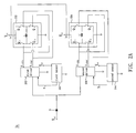
- FIG. 2A is a circuit block diagram of a driving unit of the brushless DC motor according to a first embodiment of the present invention
- FIG. 2B is a circuit block diagram of another driving unit of the brushless DC motor according to the first embodiment of the present invention.
- FIG. 2C is an exploded and schematic illustrations of the brushless DC motor according to the first embodiment of the present invention.
- FIG. 3A is a current-time diagram obtained by measuring the current at the point I of FIG. 1 ;
- FIG. 3B is a current-time diagram obtained by measuring the current at the point Ia of FIG. 2A ;
- FIG. 4 is a top view of a stator of a brushless DC motor according to a second embodiment of the present invention.
- a brushless DC motor according to a first embodiment of the present invention includes a driving unit 2 a , a rotor 26 and a stator 28 .
- the driving unit 2 a includes a power source Vcc, a first driver 202 , a first bridge circuit 222 , a first sensor 242 , a second driver 204 , a second bridge circuit 224 and a second sensor 244 .
- the first driver 202 is electrically connected with the power source Vcc and the first bridge circuit 222 for outputting a first controlling signal A 1 and a second controlling signal A 2 to the first bridge circuit 222 .
- the first controlling signal A 1 and the second controlling signal A 2 are pulse voltage signals, and the phase of the first controlling signal A 1 and the phase of the second controlling signal A 2 are opposite with each other.
- the second driver 204 is electrically connected with the power source Vcc and the second bridge circuit 224 for outputting a third controlling signal A 3 and a fourth controlling signal A 4 to the second bridge circuit 224 .
- the third controlling signal A 3 and the fourth controlling signal A 4 are pulse voltage signals, and the phase of the third controlling signal A 3 and the phase of the fourth controlling signal A 4 are opposite with each other.
- a coil L of the first bridge circuit 222 is wound on the upper pole arms 281 (please refer to FIG. 2C ) of the stator 28
- a coil L′ of the second bridge circuit 224 is wound on the lower pole arms 282 of the stator 28 , so as to generate the alternating magnetic field on the stator 28 cooperatively for driving the rotor 26 .
- the first sensor 242 is electrically connected with the power source Vcc and the first driver 202 for sensing the magnetic poles 27 of the rotor 26 (i.e., the magnetic field of the rotor 26 when the rotor 26 rotates) and outputting a first sensing signal S 1 to the first driver 202 , so as to adjust the phase of the first controlling signal A 1 and the phase of the second controlling signal A 2 for adjusting the magnetic field on the stator 28 and the rotation rate of the rotor 26 .
- the second sensor 244 is electrically connected with the power source Vcc and the second driver 204 for sensing the magnetic poles 27 of the rotor 26 (i.e., the magnetic field of the rotor 26 when the rotor 26 rotates) and outputting a second sensing signal S 2 to the second driver 204 , so as to adjust the phase of the third controlling signal A 3 and the phase of the fourth controlling signal A 4 for adjusting the magnetic field on the stator 28 and the rotation rate of the rotor 26 .
- the first bridge circuit 222 and the second sensor 244 are full-bridge circuits in this embodiment, or the first bridge circuit 222 and the second sensor 244 can be half-bridge circuits in other embodiment.
- a Hall direct driving circuit electrically connected with two coils(not shown) can be substituted for the driving unit 2 a . At least a driver, a bridge circuit and a sensor are built-in the Hall direct driving circuit.
- a driving unit 2 b can be substituted for the driving unit 2 a .
- the difference between the driving unit 2 a and the driving unit 2 b is that the first driver 202 and the second driver 204 in the driving unit 2 a are replaced by a microprocessor unit 206 in the driving unit 2 b .
- the driving unit 2 b includes the power source Vcc, the first bridge circuit 222 , the second bridge circuit 224 , the first sensor 242 , the second sensor 244 and the microprocessor unit 206 .
- the microprocessor unit 206 is electrically connected with the power source Vcc, the first bridge circuit 222 and the second bridge circuit 224 for outputting the first controlling signal A 1 and the second controlling signal A 2 to the first bridge circuit 222 and outputting the third controlling signal A 3 and the fourth controlling signal A 4 to the second bridge circuit 224 .
- the first controlling signal A 1 , the second controlling signal A 2 , the third controlling signal A 3 and the fourth controlling signal A 4 are pulse voltage signals, and the phase of the first controlling signal A 1 and the phase of the second controlling signal A 2 are opposite with each other, and the phase of the third controlling signal A 3 and the phase of the fourth controlling signal A 4 are opposite with each other.
- the coil L of the first bridge circuit 222 is wound on the upper pole arms 281 of the stator 28
- the coil L′ of the second bridge circuit 224 is wound on the lower pole arms 282 of the stator 28 , so as to generate the alternating magnetic field on the stator 28 cooperatively for driving the rotor 26 .
- the first sensor 242 is electrically connected with the power source Vcc and the microprocessor unit 206 for sensing the magnetic poles 27 of the rotor 26 (i.e., the magnetic field of the rotor 26 when the rotor 26 rotates) and outputting a first sensing signal S 1 to the microprocessor unit 206 , so as to adjust the phase of the first controlling signal A 1 and the phase of the second controlling signal A 2 for adjusting the magnetic field on the stator 28 and the rotation rate of the rotor 26 .
- the second sensor 244 is electrically connected with the power source Vcc and the microprocessor unit 206 for sensing the magnetic poles 27 of the rotor 26 (i.e., the magnetic field of the rotor 26 when the rotor 26 rotates) and outputting a second sensing signal S 2 to the microprocessor unit 206 , so as to adjust the phase of the third controlling signal A 3 and the phase of the fourth controlling signal A 4 for adjusting the magnetic field on the stator 28 and the rotation rate of the rotor 26 .
- the first bridge circuit 222 and the second sensor 244 of the driving unit 2 b are full-bridge circuits in this embodiment, or the first bridge circuit 222 and the second sensor 244 can be half-bridge circuits in other embodiment.
- a motor portion 2 c of the brushless DC motor includes the rotor 26 , the stator 28 , a printed circuit board 283 and a base 284 .
- the magnetic poles 27 (the poles of the magnetic poles 27 are N, S, N, S in this embodiment) is disposed inside the rotor 26 .
- the stator 28 includes a plurality of upper pole arms 281 and a plurality of lower pole arms 282 (there are four upper pole arms 281 and four lower pole arms 282 in this embodiment).
- the upper pole arms 281 are located above the lower pole arms 282 in FIG. 2C , but it is not limited thereto, the upper pole arms 281 can be located below the lower pole arms 282 in other embodiments.
- a first gap 2811 is formed between each two adjacent upper pole arms 281
- a second gap 2821 is formed between each two adjacent lower pole arms 282 .
- the first gaps 2811 and the second gaps 2821 are alternately arranged.
- the center of each upper pole arm 281 is corresponding to one of the second gaps 2821 respectively
- the center of each lower pole arm 282 is corresponding to one of the first gaps 2811 respectively.
- An angle is formed between an first imaginary line which connects the center of one of the first gaps 2811 and the center of the stator 28 and an second imaginary line which connects the center of one of the second gaps 2821 adjacent to the first imaginary line and the center of the stator 28 , and the angle is obeyed an equation of:
- first gaps 2811 the number of the upper pole arms 281
- second gaps 2821 the number of the lower pole arms 282
- the stator 28 can further include a third set of pole arms(not shown) or more above.
- the driving unit 2 a or the driving unit 2 b can further include a third coil, a third bridge circuit, a third sensor or elements more above electrically connected with the stator 28 for driving the rotor 26 .
- the driving unit 2 a drives the rotor 26 , and the first driver 202 , the second driver 204 , the first sensor 242 and the second sensor 244 can be disposed on the printed circuit board 283 .
- the driving unit 2 a includes at least two coils L and L′ wound on the upper pole arms 281 and the lower pole arms 282 respectively, and the driving unit 2 a generates an alternating magnetic field on the stator 28 for driving the rotor 26 .
- FIG. 3A is a current-time diagram obtained by measuring the current at the point I of FIG. 1 , wherein the power source Vcc supplies power into the bridge circuit 12 of the conventional driving circuit. It is clear in FIG. 3A that the amplitude of vibration between the highest current and the lowest current are 400 milliamperes(400 mA), so that the amplitude of the current flowing through the coil L of FIG. 1 is quite wide, and this makes the electronic elements in the motor to be broken easily.
- the waveform is intermittent and more circuitous, such as at the point T of the time axle, there is a short “dead time” which represents the current flowing through the coil L breaks off in a short period.
- the Cogging Torque of the conventional motor driven by the conventional driving circuit is greater than the Cogging Torque of the brushless DC motor of the present invention.
- FIG. 3B is a current-time diagram obtained by measuring the current at the point Ia of FIG. 2A wherein the power source Vcc supplies power into the bridge circuit 222 . It is shown in FIG. 3B that the amplitude of vibration between the highest current and the lowest current are only 200 milliamperes(200 mA), which is not too wide.
- the waveform is more continuous, because the driving unit 2 a of the present invention includes two coils L and L′, and the “dead time” will not happen on the coil L and the coil L′ at the same time.
- the first gaps 2811 and the second gaps 2821 of the stator 28 are alternately arranged, the Cogging Torque of the brushless DC motor of the present invention has been reduced obviously.
- the brushless DC motor according to a second embodiment of the present invention also includes a rotor, a stator and a driving unit, wherein the rotor and the driving unit of the second embodiment are the same with the rotor 26 and the driving unit 2 a of the first embodiment.
- the stator 48 of the second embodiment includes a plurality of pole arms 481 ⁇ 488 , and the pole arms 481 ⁇ 488 are located at the same level.
- the two coils L and L′ of the driving unit 2 a are wound on the two adjacent pole arms of the stator 48 respectively.
- the stator 48 includes a first pole arm 481 , a second pole arm 482 and a third pole arm 483 arranged orderly and located at the same level, and the coil L of the driving unit 2 a is wound on the first pole arm 481 and the second pole arm 482 , and another coil L′ of the driving unit 2 a is wound on the second pole arm 482 and the third pole arm 483 .
- the coil L is wound on the first pole arm 481 and the second pole arm 482 firstly, and then be wound on the third pole arm 483 and the fourth pole arm 484 , and afterwards be wound on the fifth pole arm 485 and the sixth pole arm 486 , finally be wound on the seventh pole arm 487 and the eighth pole arm 488 ; and the coil L′ is wound on the eighth pole arm 488 and the first pole arm 481 firstly, and then be wound on the second pole arm 482 and the third pole arm 483 , and afterwards be wound on the fourth pole arm 484 and the fifth pole arm 485 , finally be wound on the sixth pole arm 486 and the seventh pole arm 487 .
- the driving unit of the second embodiment also generates an alternating magnetic field on the stator 48 for driving the rotor.
- the number of the pole arms of the stator 48 divided by the number of the coils equals the number of the magnetic poles of the rotor.
- the number of the pole arms of the stator 48 is eight, and the number of the coils of the driving unit is two, so that the number of the magnetic poles of the rotor is four(which are poles of N, S, N, S).
- the coil winding method in this embodiment winding the coil L and the coil L′ on the pole arms of the stator 48 respectively, this method also reduces the amplitude of vibration between the highest current and the lowest current supplied into the first bridge circuit 222 and the second bridge circuit 224 , so as to prevent the damage of the electronic elements in the motor caused by an excessive Peak Current. And the waveform is also more continuous during the switch of the flowing direction of the current in this embodiment.
- the brushless DC motor of the present invention has at least two coils of a driving unit wound on a plurality of upper pole arms and lower pole arms of a stator for driving a rotor, or has at least two coils of a driving unit wound on two adjacent pole arms of the stator respectively for driving the rotor. So that the amplitude of the current supplied into the bridge circuit is low, and the pause time of the rotation of the rotor is practically negligible.
- the driving unit of the brushless DC motor of the present invention includes two bridge circuits and two sensors, so that each bridge circuit and sensor can keep the operation of the driving unit separately even when the other bridge circuit and sensor are broken, i.e., the stability of the operation of the brushless DC motor is high. When the brushless DC motor of the present invention is applied to a fan, the stability of the operation of the fan is undoubtedly high.
Landscapes
- Engineering & Computer Science (AREA)
- Power Engineering (AREA)
- Control Of Motors That Do Not Use Commutators (AREA)
- Brushless Motors (AREA)
Abstract
Description
Claims (14)
Applications Claiming Priority (3)
| Application Number | Priority Date | Filing Date | Title |
|---|---|---|---|
| TW097151168 | 2008-12-29 | ||
| TW097151168A TWI389426B (en) | 2008-12-29 | 2008-12-29 | Brushless dc motor and drive unit thereof |
| TW97151168A | 2008-12-29 |
Publications (2)
| Publication Number | Publication Date |
|---|---|
| US20100164420A1 US20100164420A1 (en) | 2010-07-01 |
| US8629639B2 true US8629639B2 (en) | 2014-01-14 |
Family
ID=42284024
Family Applications (1)
| Application Number | Title | Priority Date | Filing Date |
|---|---|---|---|
| US12/397,867 Active 2031-01-14 US8629639B2 (en) | 2008-12-29 | 2009-03-04 | Brushless direct current motor and driving unit thereof |
Country Status (2)
| Country | Link |
|---|---|
| US (1) | US8629639B2 (en) |
| TW (1) | TWI389426B (en) |
Cited By (1)
| Publication number | Priority date | Publication date | Assignee | Title |
|---|---|---|---|---|
| US20130285584A1 (en) * | 2012-04-27 | 2013-10-31 | Samsung Electro-Mechanics Co., Ltd. | Motor driving apparatus and method |
Families Citing this family (8)
| Publication number | Priority date | Publication date | Assignee | Title |
|---|---|---|---|---|
| JP5648469B2 (en) * | 2010-12-23 | 2015-01-07 | 日立工機株式会社 | Electric tool |
| TWI458253B (en) * | 2011-05-10 | 2014-10-21 | Delta Electronics Inc | Ac motor |
| TWI449303B (en) * | 2011-10-25 | 2014-08-11 | Univ Nat Sun Yat Sen | Electric power generating apparatus |
| TWI451671B (en) * | 2012-01-31 | 2014-09-01 | Sunonwealth Electr Mach Ind Co | Motor with power generating coils |
| TWI587609B (en) * | 2014-09-25 | 2017-06-11 | Dyna Rechi Co Ltd | Brushless DC motor |
| TWI556569B (en) * | 2014-09-25 | 2016-11-01 | Dyna Rechi Co Ltd | Brushless DC Motor Speed Control System |
| CN105449962A (en) * | 2014-09-29 | 2016-03-30 | 瑞展动能股份有限公司 | Brushless DC Motor |
| DE102021201617A1 (en) * | 2021-02-19 | 2022-08-25 | Robert Bosch Gesellschaft mit beschränkter Haftung | Electric motor for selective operation with at least two different supply voltages and switching device for the electric motor |
Citations (3)
| Publication number | Priority date | Publication date | Assignee | Title |
|---|---|---|---|---|
| US6498451B1 (en) * | 2000-09-06 | 2002-12-24 | Delphi Technologies, Inc. | Torque ripple free electric power steering |
| US6624541B2 (en) * | 2001-05-29 | 2003-09-23 | Sunonwealth Electric Machine Industry Co., Ltd. | Stator with a radial winding and method for manufacturing same |
| US6856054B2 (en) * | 2001-09-25 | 2005-02-15 | Matsushita Electric Industrial Co., Ltd | Brushless DC motor, pump, and electronic apparatus |
-
2008
- 2008-12-29 TW TW097151168A patent/TWI389426B/en active
-
2009
- 2009-03-04 US US12/397,867 patent/US8629639B2/en active Active
Patent Citations (3)
| Publication number | Priority date | Publication date | Assignee | Title |
|---|---|---|---|---|
| US6498451B1 (en) * | 2000-09-06 | 2002-12-24 | Delphi Technologies, Inc. | Torque ripple free electric power steering |
| US6624541B2 (en) * | 2001-05-29 | 2003-09-23 | Sunonwealth Electric Machine Industry Co., Ltd. | Stator with a radial winding and method for manufacturing same |
| US6856054B2 (en) * | 2001-09-25 | 2005-02-15 | Matsushita Electric Industrial Co., Ltd | Brushless DC motor, pump, and electronic apparatus |
Cited By (1)
| Publication number | Priority date | Publication date | Assignee | Title |
|---|---|---|---|---|
| US20130285584A1 (en) * | 2012-04-27 | 2013-10-31 | Samsung Electro-Mechanics Co., Ltd. | Motor driving apparatus and method |
Also Published As
| Publication number | Publication date |
|---|---|
| US20100164420A1 (en) | 2010-07-01 |
| TW201025798A (en) | 2010-07-01 |
| TWI389426B (en) | 2013-03-11 |
Similar Documents
| Publication | Publication Date | Title |
|---|---|---|
| US8629639B2 (en) | Brushless direct current motor and driving unit thereof | |
| CN100350726C (en) | Three-phase ring coil type permanent magnet rotary motor | |
| US9059659B2 (en) | Method and system for measuring a characteristic of an electric motor | |
| US8350503B2 (en) | Brushless motor device | |
| JP5848070B2 (en) | Brushless motor control device and brushless motor | |
| US20060055265A1 (en) | Printed circuit board motor | |
| US20080074068A1 (en) | Brushless motor | |
| US9785117B2 (en) | Motor drive device and electronic timepiece | |
| CN1515067A (en) | Method and device for driving brushless DC motor | |
| US7342367B2 (en) | Motor drive circuit, motor system, and motor drive method | |
| US10520897B2 (en) | Analog timepiece and control method of analog timepiece | |
| US20060056823A1 (en) | Fan speed control circuit | |
| US7304446B2 (en) | Sensorless and brushless DC motor | |
| US7940022B2 (en) | Motor controlling device and method thereof | |
| US8283885B2 (en) | Driver circuit | |
| US20090236922A1 (en) | High-efficiency, variable-speed permanent magnet motor and control system | |
| US8125174B2 (en) | Motor driven electronic apparatus | |
| EP3832879B1 (en) | Control of a single coil bldc motor | |
| US7154239B1 (en) | Controller for a brushless direct current motor | |
| CN101771319A (en) | Brushless DC motor and drive unit thereof | |
| KR20160050763A (en) | Motor drive device of single-phase and three-phase | |
| US8035326B2 (en) | Fan and controlling device thereof | |
| JP2002101683A (en) | Phase angle control method of brushless dc motor | |
| JP7210619B2 (en) | Brushless DC electric motor and related control method | |
| JP3107384B2 (en) | Drive device for brushless motor |
Legal Events
| Date | Code | Title | Description |
|---|---|---|---|
| AS | Assignment |
Owner name: DELTA ELECTRONICS, INC.,TAIWAN Free format text: ASSIGNMENT OF ASSIGNORS INTEREST;ASSIGNORS:WU, YEN-HUNG;HSIEH, TSUNG-JUNG;HUANG, YUEH-LUNG;REEL/FRAME:022345/0942 Effective date: 20090220 Owner name: DELTA ELECTRONICS, INC., TAIWAN Free format text: ASSIGNMENT OF ASSIGNORS INTEREST;ASSIGNORS:WU, YEN-HUNG;HSIEH, TSUNG-JUNG;HUANG, YUEH-LUNG;REEL/FRAME:022345/0942 Effective date: 20090220 |
|
| STCF | Information on status: patent grant |
Free format text: PATENTED CASE |
|
| FPAY | Fee payment |
Year of fee payment: 4 |
|
| MAFP | Maintenance fee payment |
Free format text: PAYMENT OF MAINTENANCE FEE, 8TH YEAR, LARGE ENTITY (ORIGINAL EVENT CODE: M1552); ENTITY STATUS OF PATENT OWNER: LARGE ENTITY Year of fee payment: 8 |
|
| MAFP | Maintenance fee payment |
Free format text: PAYMENT OF MAINTENANCE FEE, 12TH YEAR, LARGE ENTITY (ORIGINAL EVENT CODE: M1553); ENTITY STATUS OF PATENT OWNER: LARGE ENTITY Year of fee payment: 12 |