US8625933B2 - Image processing apparatus and method for the same - Google Patents
Image processing apparatus and method for the same Download PDFInfo
- Publication number
- US8625933B2 US8625933B2 US12/571,658 US57165809A US8625933B2 US 8625933 B2 US8625933 B2 US 8625933B2 US 57165809 A US57165809 A US 57165809A US 8625933 B2 US8625933 B2 US 8625933B2
- Authority
- US
- United States
- Prior art keywords
- image
- image data
- unit
- zooming
- magnification
- Prior art date
- Legal status (The legal status is an assumption and is not a legal conclusion. Google has not performed a legal analysis and makes no representation as to the accuracy of the status listed.)
- Expired - Fee Related, expires
Links
Images


Classifications
-
- G—PHYSICS
- G09—EDUCATION; CRYPTOGRAPHY; DISPLAY; ADVERTISING; SEALS
- G09G—ARRANGEMENTS OR CIRCUITS FOR CONTROL OF INDICATING DEVICES USING STATIC MEANS TO PRESENT VARIABLE INFORMATION
- G09G5/00—Control arrangements or circuits for visual indicators common to cathode-ray tube indicators and other visual indicators
- G09G5/36—Control arrangements or circuits for visual indicators common to cathode-ray tube indicators and other visual indicators characterised by the display of a graphic pattern, e.g. using an all-points-addressable [APA] memory
- G09G5/39—Control of the bit-mapped memory
- G09G5/391—Resolution modifying circuits, e.g. variable screen formats
-
- G—PHYSICS
- G09—EDUCATION; CRYPTOGRAPHY; DISPLAY; ADVERTISING; SEALS
- G09G—ARRANGEMENTS OR CIRCUITS FOR CONTROL OF INDICATING DEVICES USING STATIC MEANS TO PRESENT VARIABLE INFORMATION
- G09G2340/00—Aspects of display data processing
- G09G2340/04—Changes in size, position or resolution of an image
- G09G2340/045—Zooming at least part of an image, i.e. enlarging it or shrinking it
Definitions
- the present invention relates to image processing, and more particularly to a technique capable of detecting an imaging object pattern from a moving image.
- an image processing method which can automatically detect a predetermined imaging object pattern from a moving image has been discussed and the method can be used to determine, for example, a human face or the like.
- This kind of image processing method can be used in a video conference, a monitoring system, or the like.
- Such techniques that can be used to detect a predetermined imaging object pattern from an image are, for example, discussed in Japanese Patent Application Laid-Open No. 2007-25899, Japanese Patent Application Laid-Open No. 2004-171490, and Japanese Patent Application Laid-Open No. 2003-235035 according to which the predetermined imaging object pattern can be detected using a template matching technique.
- the system may not perform tracking using panning and tilting functions when the predetermined imaging object exits from the frame between non-processed frames.
- the system performs normal detection processing at constant frame intervals and inserts a frame that detects only a position adjacent to a coordinate of the already detected imaging object between two frames at which the normal detection processing is performed. This system intends to reduce the burden in calculations for the template matching processing.
- the imaging object may not be captured in a detection area if a moving speed of the imaging object is inappropriate.
- the imaging object cannot be detected in this case.
- the imaging object may not be detected based on only the detection at or near the coordinate position of the previous detection frame.
- the system obtains a difference between an input image and a background image and registers the obtained difference as a template.
- a predetermined imaging object in the template is identical to a predetermined imaging object in the original input image.
- the system performs conversion in resolution based on the zooming parameter to equalize in size the predetermined imaging object of the input image with the predetermined imaging object of the template, so that the imaging object pattern can be detected.
- this technique is only effective in an operation for tracking an imaging object that has been captured in the input image and cannot be used in a situation where the distance between the imaging object and the camera is variable. Accordingly, detection accuracy deteriorates when the distance between the imaging object and the camera is changed.
- Exemplary embodiments of the present invention are directed to a technique capable of reducing a burden in calculations for detecting an imaging object pattern and capable of maintaining accuracy in detection of the imaging object pattern.
- an image processing apparatus can detect a predetermined target object from image data.
- the image processing apparatus includes an image inputting unit configured to input the image data, a detected pattern storage unit configured to store a detection pattern representing the predetermined target object, an image zooming unit configured to generate a plurality of pieces of zoomed image data that are mutually different in magnification from the image data input by the image inputting unit, a detection unit configured to extract a partial area from the plurality of pieces of zoomed image data generated by the image zooming unit, and detect the predetermined target object by performing collation to determine whether the extracted partial area coincides with the detection pattern stored in the detected pattern storage unit, and a detected information storage unit configured to store detection information including magnification information of the zoomed image data from which the predetermined target object is detected by the detection unit.
- the image zooming unit determines a magnification of the zoomed image data based on the detection information and generates at least one piece of zoomed image data whose total number is smaller compared to a case where the detection information is not stored.
- FIG. 1 is a block diagram illustrating an example of the configuration of an image processing apparatus according to a first exemplary embodiment of the present invention.
- FIGS. 2A and 2B are flowcharts illustrating an example of processing procedure for detecting a predetermined pattern which can be performed by the image processing apparatus according to the first exemplary embodiment.
- FIGS. 3A and 3B illustrate an example of collating processing to be performed to check whether a collation object pattern coincides with a detection pattern with respect to various reduced images that are different in size according to the first exemplary embodiment.
- FIG. 4 is a block diagram illustrating an example of the configuration of an image processing apparatus according to a second exemplary embodiment of the present invention.
- FIGS. 5A and 5B are flowcharts illustrating an example of a processing procedure for detecting a predetermined pattern which can be performed by the image processing apparatus according to the second exemplary embodiment.
- FIGS. 6A and 6B illustrate an example of collating processing to be performed to check whether a collation object pattern coincides with a detection pattern with respect to various reduced images that are different in size according to the second exemplary embodiment.
- FIG. 7 is a block diagram illustrating an example of the configuration of an image processing apparatus according to a third exemplary embodiment of the present invention.
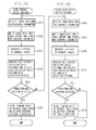
- FIGS. 8A and 8B are flowcharts illustrating an example of a processing procedure for detecting a predetermined pattern which can be performed by the image processing apparatus according to the third exemplary embodiment.
- FIG. 9 is a block diagram illustrating an example of the configuration of an image processing apparatus according to a fourth exemplary embodiment of the present invention.
- FIGS. 10A and 10B are flowcharts illustrating an example of a processing procedure for detecting a predetermined pattern which can be performed by image processing apparatus according to the fourth exemplary embodiment.
- FIG. 1 is a block diagram illustrating an example of the configuration of an image processing apparatus 1 according to an exemplary embodiment of the present invention. First, the configuration of the image processing apparatus 1 according to the present exemplary embodiment is described below.
- an image inputting unit 11 receives image data.
- the image inputting unit 11 has a decoding processing function for receiving image data that may be conformable to a specific communication method and compatible with a marker code-attached protocol or compression processed image data such as Joint Photographic Experts Group (JPEG)/Motion Joint Photographic Experts Group 4 (MPEG4).
- JPEG Joint Photographic Experts Group
- MPEG4 Motion Joint Photographic Experts Group 4
- the image data include photographic image data captured and generated by an imaging apparatus and image data stored in an external storage apparatus.
- An output source is not limited to a specific device.
- An image memory 12 can be configured by a random access memory (RAM) or other readable and writable storage apparatus.
- the image memory 12 stores the image data received by the image inputting unit 11 and zooming processed image data supplied from an image zooming unit 13 .
- the image zooming unit 13 can read the image data stored in the image memory 12 and generate reduced image data (i.e., zoomed image data).
- the image zooming unit 13 can write the reduced image data into the image memory 12 .
- a collation object pattern extraction unit 14 can move a rectangular area which has a predetermined size on the reduced image data stored in the image memory 12 and successively extract and output a portion (i.e., a pixel group) included in the rectangular area as a collation object pattern.
- an original image can be regarded as an image having a reduced size of 1/1 and can be interpreted as one of the reduced images.
- a detected pattern storage unit 15 can store beforehand a detection pattern that represents a predetermined pattern (target object) to be detected from an input image.
- a pattern detection unit 16 performs collation based on the detection pattern stored in the detected pattern storage unit 15 to determine whether the collation object pattern coincides with the predetermined pattern.
- a detected information storage unit 17 can receive magnification information relating to a zooming ratio of the reduced image which is used when the predetermined pattern is detected by the pattern detection unit 16 .
- the detected information storage unit 17 stores the magnification information received from the pattern detection unit 16 .
- the image processing apparatus 1 can provide two types of detection modes (i.e., a normal detection mode and a high-speed detection mode) which can be selected in detection of the predetermined pattern. It is now assumed that the image processing apparatus 1 starts its operation in the normal detection mode.
- FIG. 2A is a flowchart illustrating an example of a processing procedure for detecting a predetermined pattern, which can be performed by the image processing apparatus 1 that operates in the normal detection mode according to the present exemplary embodiment.
- the image inputting unit 11 receives image data.
- the received image data is the image data that may be conformable to the specific communication method and compatible with the marker code-attached protocol or the compression processed image data such as JPEG/MPEG4, the image inputting unit 11 performs decoding processing on the received image data.
- step S 102 the image inputting unit 11 writes the processing result as input image data into the image memory 12 .
- the image inputting unit 11 directly writes the received image data as input image data into the image memory 12 .
- step S 103 the image zooming unit 13 reads the input image data stored in the image memory 12 and generates n (n ⁇ 2) pieces of reduced image data.
- the image zooming unit 13 writes the generated reduced image data into the image memory 12 .
- the input image is of a Video Graphic Array (VGA) size (640 pixels in the horizontal direction and 480 pixels in the vertical direction).
- VGA Video Graphic Array
- the image zooming unit 13 reduces the input VGA data and generates first reduced image A 1 data which has a size of 320 pixels in the horizontal direction and 240 pixels in the vertical direction.
- the image zooming unit 13 writes the first reduced image A 1 data into the image memory 12 .
- the image zooming unit 13 reads the reduced image A 1 data from the image memory 12 and generates second reduced image A 2 data which has a size comparable to 0.8 times the reduced image A 1 data in both the horizontal and vertical directions.
- the image zooming unit 13 writes the second reduced image A 2 data into the image memory 12 .
- the image zooming unit 13 repeats similar reduction processing until n-th reduced image An data can be obtained.
- a zooming ratio (i.e., a magnification of an image relative to the input image) in generation of the reduced image data is a mere example.
- the value n can be changed considering various conditions, such as the size of the input image or the size of the detection pattern. Alternatively, the value n can be a fixed value.
- the zooming ratios for generating the data of the reduced images A 1 to An can be referred to as magnifications A 1 to An.
- step S 104 the collation object pattern extraction unit 14 moves a rectangular area having a predetermined size on the data of the reduced images A 1 to An in a direction indicated by an arrow, as illustrated in FIG. 3A , and successively extracts a portion (i.e., a pixel group) included in the rectangular area as a collation object pattern. Then, the portions (i.e., pixel groups) extracted by the collation object pattern extraction unit 14 are output to the pattern detection unit 16 .
- the “predetermined size” can be arbitrarily determined to be a size equal to or greater than the reduced image An, although the rectangular area illustrated in FIG. 3A is similar in size to the detection pattern.
- the procedure indicated by the arrow is a mere example. The procedure for the successive extraction may be arbitrarily changed.
- the pattern detection unit 16 successively performs collation to determine whether each collation object pattern extracted by the collation object pattern extraction unit 14 coincides with the predetermined pattern, referring to the detection pattern stored in the detected pattern storage unit 15 .
- the image processing apparatus 1 can generate a total of n pieces of reduced image data and perform collation on the generated n pieces of reduced image data.
- step S 105 it is determined whether the predetermined pattern has been detected referring to a result of the collation performed on the reduced images A 1 to An. If it is determined that the predetermined pattern has not been detected (NO in step S 105 ), the processing returns to step S 101 to repeat the processing of steps S 101 to S 104 . On the other hand, if it is determined that the predetermined pattern has been detected (YES in step S 105 ), the processing proceeds to step S 106 .
- step S 105 the pattern detection unit 16 has detected the predetermined pattern from the reduced image A 6 (i.e., the sixth reduced image).
- the detected information storage unit 17 receives information indicating a magnification A 6 of the reduced image A 6 , which is a zooming ratio relative to the input image, from the pattern detection unit 16 .
- the detected information storage unit 17 stores the received zooming ratio information.
- the image processing apparatus 1 terminates the operation in the normal detection mode and shifts its operation mode to the high-speed detection mode.
- FIG. 2B is a flowchart illustrating an example of a processing procedure for detecting a predetermined pattern, which can be performed by the image processing apparatus 1 that operates in the high-speed detection mode according to the present exemplary embodiment.
- step S 107 the image inputting unit 11 receives image data of the next latest frame.
- step S 108 similar to step S 102 , the image inputting unit 11 writes the received image data as input image data into the image memory 12 .
- step S 109 the image zooming unit 13 reads the input image data stored in the image memory 12 and generates m (n>m ⁇ 1) pieces of reduced image data.
- the image zooming unit 13 writes the generated reduced image data into the image memory 12 .
- the reduction magnification for generating the reduced image data can be determined based on the zooming ratio stored in the detected information storage unit 17 .
- the detected information storage unit 17 may store image size information instead of the zooming ratio information and can determine a reduction magnification based on the image size information.
- the zooming ratio of the reduced image from which the predetermined pattern has been detected is the magnification A 6 .
- the detected information storage unit 17 stores the information indicating the magnification A 6 .
- the image zooming unit 13 writes the generated reduced image B 1 data into the image memory 12 .
- the image zooming unit 13 generates the reduced image B 1 data from the input image data using a magnification A 5 that is a zooming ratio comparable to 1.25 times the magnification A 6 stored in the detected information storage unit 17 .
- the image zooming unit 13 writes the generated reduced image B 1 data into the image memory 12 .
- the image zooming unit 13 reads the reduced image B 1 data from the image memory 12 and generates reduced image B 2 data which has a size comparable to 0.8 times the reduced image B 1 data in both the horizontal and vertical directions.
- the image zooming unit 13 writes the second reduced image B 2 data into the image memory 12 .
- the zooming ratio in this case is equal to the magnification A 6 stored in the detected information storage unit 17 .
- the image zooming unit 13 writes the generated third reduced image B 3 data into the image memory 12 .
- the zooming ratio in this case is equal to the magnification A 7 .
- the image zooming unit 13 generates m pieces of reduced image data using a zooming ratio adjacent to the zooming ratio stored in the detected information storage unit 17 among the n pieces of zooming ratios in the generation of n pieces of reduced image data.
- step S 110 the collation object pattern extraction unit 14 moves a rectangular area having a predetermined size on the data of the reduced images B 1 to Bm in a direction indicated by an arrow, as illustrated in FIG. 3B , and successively extracts a portion (i.e., a pixel group) included in the rectangular area as a collation object pattern. Then, the portions (i.e., pixel groups) extracted by the collation object pattern extraction unit 14 are output to the pattern detection unit 16 .
- the pattern detection unit 16 successively performs collation to determine whether each collation object pattern extracted by the collation object pattern extraction unit 14 coincides with the predetermined pattern, referring to the detection pattern stored in the detected pattern storage unit 15 .
- the processing in step S 110 is different from the above-described processing in step S 104 in that the total number of the reduced image data is m that is smaller than n.
- the image processing apparatus 1 can generate a total of m pieces of reduced image data and perform collation on the generated m pieces of reduced image data.
- step S 111 it is determined whether the predetermined pattern has been detected referring to a result of the collation performed on the reduced images B 1 to Bm. If it is determined that the predetermined pattern has not been detected (NO in step S 111 ), the image processing apparatus 1 terminates the operation in the high-speed detection mode. Then, the detected information storage unit 17 deletes the stored information indicating the magnification A 6 . The image processing apparatus 1 starts its operation in the normal detection mode. On the other hand, if it is determined that the predetermined pattern has been detected (YES in step S 111 ), the processing proceeds to step S 112 .
- step S 112 the detected information storage unit 17 deletes the stored information indicating the magnification A 6 .
- the detected information storage unit 17 receives information indicating a magnification B 3 of the reduced image B 3 , which is a zooming ratio relative to the input image, from the pattern detection unit 16 .
- the detected information storage unit 17 newly stores the received zooming ratio information. Then, the processing returns to step S 107 to execute the processing of steps S 107 to S 111 , similar to the above-described procedure.
- the pattern detection unit 16 may have luminance correction processing, density correction processing, and background removal processing functions, which are conventionally known.
- the pattern detection unit 16 can perform the luminance correction processing, the density correction processing, and the background removal processing on the collation object patterns. This is effective to improve accuracy of the collation performed by the pattern detection unit 16 .
- an image processing unit configured to perform the luminance correction processing, the density correction processing, and the background removal processing on the input image or the reduced images. This is also effective to improve the accuracy of the collation performed by the pattern detection unit 16 .
- the image zooming unit 13 can extract only the luminance component and generate reduced image data based on the extracted luminance component.
- the present exemplary embodiment uses a total of n (n ⁇ 2) pieces of reduced images that are sufficient for detecting a predetermined pattern on condition that the size of a predetermined imaging object on the input image is unclear.
- the present exemplary embodiment uses m (n>m ⁇ 1) pieces of reduced images to detect the predetermined pattern considering the situation that the size of the predetermined imaging object on the input image is already known.
- the present exemplary embodiment limits the zooming ratio to be used to generate reduced image data referring to the zooming ratio stored in the detected information storage unit 17 . Therefore, the present exemplary embodiment can reduce the amount of reduced image data to be generated to detect the predetermined pattern. Therefore, the present exemplary embodiment can reduce a burden in calculation processing by decreasing the processing amount in the zooming processing as well as in the collation. Thus, the present exemplary embodiment can speedily detect the predetermined imaging object.
- the present exemplary embodiment can maintain the detection accuracy because of m>1 even when the zooming processing amount is decreased and when the size of predetermined imaging object on the input image is changed.
- the image processing apparatus 1 according to the present exemplary embodiment is configured to receive image data from an external device. However, similar effects can be obtained even in a case where the image processing apparatus 1 is integrated with an imaging apparatus or other image data outputting source.
- FIG. 4 is a block diagram illustrating an example of the configuration of an image processing apparatus 20 according to the present exemplary embodiment. First, an example of the configuration of the image processing apparatus 20 according to the present exemplary embodiment is described below.
- an image inputting unit 21 receives image data from an external imaging apparatus 2 . Further, the image inputting unit 21 has a decoding processing function for receiving image data that may be conformable to a specific communication method and compatible with a marker code-attached protocol or compression processed image data such as JPEG/MPEG4.
- the imaging apparatus 2 is a general camera that includes a charge-coupled device (CCD) or a complementary metal oxide semiconductor (CMOS) configured to receive incident light via a zoom lens that can change a photographic angle of view.
- the imaging apparatus 2 can generate photographic image data constituted by digital data that are photo-electrically converted by the CCD or CMOS.
- the imaging apparatus 2 can output photographic parameters including at least a zooming magnification, together with the photographic image data, to the image processing apparatus 20 .
- a photographic parameter storage unit 28 can receive the photographic parameters output from the imaging apparatus 2 and store the received photographic parameters as parameter information.
- a general network line such as a local area network (LAN), or a dedicated cable can be used to transmit or receive various data between the imaging apparatus 2 and the image processing apparatus 20 .
- LAN local area network
- An image memory 22 can be configured by a readable and writable storage apparatus (e.g., a RAM).
- the image memory 22 stores the image data received by the image inputting unit 21 and zooming processed image data supplied from an image zooming unit 23 .
- the image zooming unit 23 can read the image data stored in the image memory 22 and generate reduced image data (i.e., zoomed image data).
- the image zooming unit 23 can write the reduced image data into the image memory 22 .
- a collation object pattern extraction unit 24 can move a rectangular area having a predetermined size on the reduced image data stored in the image memory 22 and successively extract and output a portion (i.e., a pixel group) included in the rectangular area as a collation object pattern.
- an original image can be regarded as an image having a reduced size of 1/1 and can be interpreted as one of the reduced images.
- a detected pattern storage unit 25 can store beforehand a detection pattern that represents a predetermined pattern (target object) to be detected from an input image.
- a pattern detection unit 26 performs collation based on the detection pattern stored in the detected pattern storage unit 25 to determine whether the collation object pattern coincides with the predetermined pattern.
- a detected information storage unit 27 can receive magnification information relating to a zooming ratio of the reduced image which is used when the predetermined pattern is detected by the pattern detection unit 26 .
- the detected information storage unit 27 stores the magnification information received from the pattern detection unit 26 .
- the image processing apparatus 20 can provide two types of detection modes (i.e., the normal detection mode and the high-speed detection mode) which can be selected in detection of the predetermined pattern. It is now assumed that the image processing apparatus 20 starts its operation in the normal detection mode.
- FIG. 5A is a flowchart illustrating an example of a processing procedure for detecting a predetermined pattern, which can be performed by the image processing apparatus 20 that operates in the normal detection mode according to the present exemplary embodiment.
- the image inputting unit 21 receives image data from the imaging apparatus 2 .
- the photographic parameter storage unit 28 receives the photographic parameters relating to the image data received by the image inputting unit 21 .
- step S 202 the image inputting unit 21 writes the input image data into the image memory 22 .
- the image inputting unit 21 performs marker code removal or similar decoding processing on the received image data.
- the image inputting unit 21 writes the processing result as input image data into the image memory 22 .
- the image inputting unit 21 performs decompression processing or similar decoding processing on the received image data.
- the image inputting unit 21 writes the processing result as input image data into the image memory 22 .
- the image inputting unit 21 directly writes the received image data as input image data into the image memory 22 .
- the photographic parameter storage unit 28 stores the received photographic parameters.
- step S 203 the image zooming unit 23 reads the input image data stored in the image memory 22 and generates n (n ⁇ 2) pieces of reduced image data.
- the image zooming unit 23 writes the generated reduced image data into the image memory 22 .
- the input image is of VGA size (640 pixels in the horizontal direction and 480 pixels in the vertical direction).
- the image zooming unit 23 reduces the input VGA data and generates first reduced image A 1 data which has a size of 320 pixels in the horizontal direction and 240 pixels in the vertical direction.
- the image zooming unit 23 writes the first reduced image A 1 data into the image memory 22 .
- the image zooming unit 23 reads the reduced image A 1 data from the image memory 22 and generates second reduced image A 2 data which has a size comparable to 0.8 times the reduced image A 1 data in both the horizontal and vertical directions.
- the image zooming unit 23 writes the second reduced image A 2 data into the image memory 22 .
- the image zooming unit 23 repeats similar reduction processing until n-th reduced image An data can be obtained.
- a zooming ratio i.e., a magnification of an image relative to the input image
- the value n can be changed considering various conditions, such as the size of the input image or the size of the detection pattern.
- the value n can be a fixed value.
- magnifications A 1 to An the zooming ratios for generating the data of the reduced images A 1 to An.
- step S 204 the collation object pattern extraction unit 24 moves a rectangular area having a predetermined size on the data of the reduced images A 1 to An in a direction indicated by an arrow, as illustrated in FIG. 6A , and successively extracts a portion (i.e., a pixel group) included in the rectangular area as a collation object pattern. Then, the portions (i.e., pixel groups) extracted by the collation object pattern extraction unit 24 are output to the pattern detection unit 26 .
- the “predetermined size” can be arbitrarily determined to be a size equal to or greater than the reduced image An, although the rectangular area illustrated in FIG. 6A is similar in size to the detection pattern.
- the procedure indicated by the arrow is a mere example. The procedure for the successive extraction may be arbitrarily changed.
- the pattern detection unit 26 successively performs collation to determine whether each collation object pattern extracted by the collation object pattern extraction unit 24 coincides with the predetermined pattern, referring to the detection pattern stored in the detected pattern storage unit 25 .
- the image processing apparatus 20 can generate a total of n pieces of reduced image data and perform collation on the generated n pieces of reduced image data.
- step S 205 it is determined whether the predetermined pattern is detected based on the result of the collation performed on the reduced images A 1 to An. If it is determined that the predetermined pattern is not detected (NO in step S 205 ), the processing returns to step S 201 to repeat the processing of steps S 201 to S 204 . On the other hand, if it is determined that the predetermined pattern is detected (YES in step S 205 ), the processing proceeds to step S 206 .
- step S 205 the pattern detection unit 26 has detected the predetermined pattern from the reduced image A 6 (i.e., the sixth reduced image).
- the detected information storage unit 27 receives information indicating a magnification A 6 of the reduced image A 6 , which is a zooming ratio relative to the input image, from the pattern detection unit 26 .
- the detected information storage unit 27 stores the received zooming ratio information. Then, after the zooming ratio information is stored in the detected information storage unit 27 , the image processing apparatus 20 terminates the operation in the normal detection mode and shifts its operation mode to the high-speed detection mode.
- FIG. 5B is a flowchart illustrating an example of a processing procedure for detecting a predetermined pattern, that can be performed by the image processing apparatus 20 that operates in the high-speed detection mode according to the present exemplary embodiment.
- step S 207 the image inputting unit 21 receives image data of the next latest frame from the imaging apparatus 2 .
- the photographic parameter storage unit 28 receives photographic parameters relating to the image data received by the image inputting unit 21 .
- step S 208 similar to step S 202 , the image inputting unit 21 writes the received image data as input image data into the image memory 22 .
- the photographic parameter storage unit 28 stores the photographic parameters of the latest frame so as to be added to the photographic parameters of a preceding frame.
- step S 209 the image zooming unit 23 reads the input image data stored in the image memory 22 and generates m (n>m ⁇ 1) pieces of reduced image data.
- the image zooming unit 23 writes the generated reduced image data into the image memory 22 .
- the reduction magnification for generating the reduced image data can be determined based on the zooming ratio stored in the detected information storage unit 27 and the photographic parameters (including the zooming magnification of the imaging apparatus 2 ) stored in the photographic parameter storage unit 28 .
- the zooming ratio of the reduced image from which the predetermined pattern has been detected is the magnification A 6 .
- the detected information storage unit 27 stores the information indicating the magnification A 6 .
- a zooming ratio A 6 ′ for generating the reduced image of the latest frame can be obtained according to the following formula.
- the image zooming unit 23 writes the generated reduced image B 1 data into the image memory 22 .
- the image zooming unit 23 reads the reduced image B 1 data from the image memory 22 and generates reduced image B 2 data which has a size comparable to 0.8 times the reduced image B 1 data in both the horizontal and vertical directions.
- the image zooming unit 23 writes the second reduced image B 2 data into the image memory 22 .
- the zooming ratio in this case is equal to the magnification A 6 ′.
- the image zooming unit 23 writes the generated reduced image B 3 into the image memory 22 .
- the image zooming unit 23 generates m pieces of reduced image data using a zooming ratio adjacent to the zooming ratio that can be determined based on the zooming ratio stored in the detected information storage unit 27 and the photographic parameters stored in the photographic parameter storage unit 28 .
- step S 210 the collation object pattern extraction unit 24 moves a rectangular area having a predetermined size on the data of the reduced images B 1 to Bm in a direction indicated by an arrow, as illustrated in FIG. 6B , and successively extracts a portion (i.e., a pixel group) included in the rectangular area as a collation object pattern. Then, the portions (i.e., pixel groups) extracted by the collation object pattern extraction unit 24 are output to the pattern detection unit 26 .
- the pattern detection unit 26 successively performs collation to determine whether each collation object pattern extracted by the collation object pattern extraction unit 24 coincides with the predetermined pattern, referring to the detection pattern stored in the detected pattern storage unit 25 .
- the processing in step S 210 is different from the above-described processing in step S 204 in that the total number of the reduced image data is m that is smaller than n.
- the image processing apparatus 20 can generate a total of m pieces of reduced image data and perform collation on the generated m pieces of reduced image data.
- step S 211 it is determined whether the predetermined pattern has been detected referring to a result of the collation performed on the reduced images B 1 to Bm. If it is determined that the predetermined pattern has not been detected (NO in step S 211 ), the image processing apparatus 20 terminates the operation in the high-speed detection mode. Then, the detected information storage unit 27 deletes the stored information indicating the magnification A 6 . The image processing apparatus 20 starts its operation in the normal detection mode. On the other hand, if it is determined that the predetermined pattern has been detected (YES in step S 211 ), the processing proceeds to step S 212 .
- step S 212 the detected information storage unit 27 deletes the stored information indicating the magnification A 6 .
- the detected information storage unit 27 receives information indicating a magnification B 3 of the reduced image B 3 , which is a zooming ratio relative to the input image, from the pattern detection unit 26 .
- the detected information storage unit 27 newly stores the received zooming ratio information.
- the processing returns to step S 207 to execute the processing of steps S 207 to S 211 , similar to the above-described procedure.
- the photographic parameter storage unit 28 stores two photographic parameters.
- the photographic parameter storage unit 28 can store a change amount between two photographic parameters. For example, if the zooming magnification of the preceding frame is 2 and the zooming magnification of the latest frame is 5, the photographic parameter storage unit 28 can store 2.5 as a change amount.
- the pattern detection unit 26 may have luminance correction processing, density correction processing, and background removal processing functions, which are conventionally known.
- the pattern detection unit 26 can perform the luminance correction processing, the density correction processing, and the background removal processing on the collation object patterns. This is effective to improve the accuracy of the collation performed by the pattern detection unit 26 .
- an image processing unit configured to perform the luminance correction processing, the density correction processing, and the background removal processing on the input image or the reduced images. This is also effective to improve the accuracy of the collation performed by the pattern detection unit 26 .
- the image zooming unit 23 can extract only the luminance component and generate reduced image data based on the extracted luminance component.
- the present exemplary embodiment uses a total of n (n ⁇ 2) pieces of reduced images that are sufficient for detecting a predetermined pattern on condition that the size of a predetermined imaging object on the input image is unclear.
- the present exemplary embodiment uses m (n>m ⁇ 1) pieces of reduced images to detect the predetermined pattern considering the situation that the size of the predetermined imaging object on the input image is already known.
- the present exemplary embodiment limits the zooming ratio to be used to generate reduced image data referring to the zooming ratio stored in the detected information storage unit 27 and the photographic parameter (i.e., the zooming magnification) stored in the photographic parameter storage unit 28 . Therefore, the present exemplary embodiment can reduce the amount of reduced image data to be generated to detect the predetermined pattern even in a case where the size of the imaging object on the input image is changed by a zooming operation of the imaging apparatus 2 .
- the present exemplary embodiment can reduce the burden in calculation processing by decreasing the processing amount in the zooming processing as well as in the collation.
- the present exemplary embodiment can speedily detect the predetermined imaging object.
- the present exemplary embodiment can maintain the detection accuracy because of m>1 even when the zooming processing amount is decreased and when the size of predetermined imaging object on the input image is changed due to change in a distance between the imaging object and the imaging apparatus.
- the image processing apparatus 20 according to the present exemplary embodiment is connected to the imaging apparatus 2 via a general network line or a dedicated cable. However, similar effects can be obtained even in a case where the image processing apparatus 20 is integrated with the imaging apparatus 2 .
- FIG. 7 is a block diagram illustrating an example of the configuration of an image processing apparatus 30 according to the present exemplary embodiment. First, an example of the configuration of the image processing apparatus 30 according to the present exemplary embodiment is described below.
- an image inputting unit 31 can receive image data from the external imaging apparatus 2 . Further, the image inputting unit 31 has a decoding processing function for receiving image data that may be conformable to a specific communication method and compatible with a marker code-attached protocol or compression processed image data such as JPEG/MPEG4.
- the imaging apparatus 2 is a general camera that includes a CCD or a CMOS configured to receive incident light via a zoom lens that can change a photographic angle of view.
- the imaging apparatus 2 can generate photographic image data constituted by digital data that are photo-electrically converted by the CCD or CMOS.
- the imaging apparatus 2 can output photographic parameters including at least a zooming magnification, together with the photographic image data, to the image processing apparatus 30 .
- a photographic parameter storage unit 38 can receive the photographic parameters output from the imaging apparatus 2 and store the received photographic parameters as parameter information.
- a general network line, such as LAN, or a dedicated cable can be used to transmit or receive various data between the imaging apparatus 2 and the image processing apparatus 30 .
- An image memory 32 can be configured by a readable and writable storage apparatus (e.g., a RAM).
- the image memory 22 stores the image data received by the image inputting unit 31 and zooming processed image data supplied from an image zooming unit 33 .
- the image zooming unit 33 can read the image data stored in the image memory 32 and generate reduced image data (i.e., zoomed image data).
- the image zooming unit 33 can write the reduced image data into the image memory 32 .
- a collation object pattern extraction unit 34 can move a rectangular area having a predetermined size on the reduced image data stored in the image memory 32 and successively extract and output a portion (i.e., a pixel group) included in the rectangular area as a collation object pattern.
- an original image can be regarded as an image having a reduced size of 1/1 and can be interpreted as one of the reduced images.
- a detected pattern storage unit 35 can store beforehand a detection pattern that represents a predetermined pattern (target object) to be detected from an input image.
- a pattern detection unit 36 performs collation based on the detection pattern stored in the detected pattern storage unit 35 to determine whether the collation object pattern coincides with the predetermined pattern.
- a detected information storage unit 37 can receive magnification information relating to a zooming ratio of the reduced image and position information of the collation object pattern which are used when the predetermined pattern is detected by the pattern detection unit 36 .
- the detected information storage unit 37 stores the magnification information and the position information received from the pattern detection unit 36 .
- the detected information storage unit 37 transmits the position information of the collation object pattern to the imaging apparatus 2 .
- the image processing apparatus 30 can provide two types of detection modes (i.e., the normal detection mode and the high-speed detection mode) which can be selected in detection of the predetermined pattern. It is now assumed that the image processing apparatus 30 starts its operation in the normal detection mode.
- FIG. 8A is a flowchart illustrating an example of a processing procedure for detecting a predetermined pattern, which can be performed by the image processing apparatus 30 that operates in the normal detection mode according to the present exemplary embodiment.
- step S 301 the image inputting unit 31 receives image data from the imaging apparatus 2 .
- the photographic parameter storage unit 38 receives the photographic parameters relating to image data received by the image inputting unit 31 .
- step S 302 the image inputting unit 31 writes the input image data into the image memory 32 .
- the image inputting unit 31 performs marker code removal or similar decoding processing on the received image data.
- the image inputting unit 31 writes the processing result as input image data into the image memory 32 .
- the image inputting unit 31 performs decompression processing or similar decoding processing on the received image data.
- the image inputting unit 31 writes the processing result as input image data into the image memory 32 .
- the image inputting unit 31 directly writes the received image data as input image data into the image memory 32 .
- the photographic parameter storage unit 38 stores the received photographic parameters.
- step S 303 the image zooming unit 33 reads the input image data stored in the image memory 32 and generates n (n ⁇ 2) pieces of reduced image data.
- the image zooming unit 33 writes the generated reduced image data into the image memory 32 .
- the input image is of VGA size (640 pixels in the horizontal direction and 480 pixels in the vertical direction).
- the image zooming unit 33 reduces the input VGA data and generates first reduced image A 1 data which has a size of 320 pixels in the horizontal direction and 240 pixels in the vertical direction.
- the image zooming unit 33 writes the first reduced image A 1 data into the image memory 32 .
- the image zooming unit 33 reads the reduced image A 1 data from the image memory 32 and generates second reduced image A 2 data which has a size comparable to 0.8 times the reduced image A 1 data in both the horizontal and vertical directions.
- the image zooming unit 33 writes the second reduced image A 2 data into the image memory 32 .
- the image zooming unit 33 repeats similar reduction processing until n-th reduced image An data can be obtained.
- a zooming ratio i.e., a magnification of an image relative to the input image
- the value n can be changed considering various conditions, such as the size of the input image or the size of the detection pattern.
- the value n can be a fixed value.
- magnifications A 1 to An the zooming ratios for generating the data of the reduced images A 1 to An.
- step S 304 the collation object pattern extraction unit 34 moves a rectangular area having a predetermined size on the data of the reduced images A 1 to An in a direction indicated by an arrow, as illustrated in FIG. 6A , and successively extracts a portion (i.e., a pixel group) included in the rectangular area as a collation object pattern. Then, the portions (i.e., pixel groups) extracted by the collation object pattern extraction unit 34 are output to the pattern detection unit 36 .
- the “predetermined size” can be arbitrarily determined to be a size equal to or greater than the reduced image An, although the rectangular area illustrated in FIG. 6A is similar in size to the detection pattern.
- the procedure indicated by the arrow is a mere example. The procedure for the successive extraction may be arbitrarily changed.
- the pattern detection unit 36 successively performs collation to determine whether each collation object pattern extracted by the collation object pattern extraction unit 34 coincides with the predetermined pattern, referring to the detection pattern stored in the detected pattern storage unit 35 .
- the image processing apparatus 30 can generate a total of n pieces of reduced image data and perform collation on the generated n pieces of reduced image data.
- step S 305 it is determined whether the predetermined pattern is detected based on the result of the collation performed on the reduced images A 1 to An. If it is determined that the predetermined pattern is not detected (NO in step S 505 ), the processing returns to step S 301 to repeat the processing of steps S 301 to S 304 . On the other hand, if it is determined that the predetermined pattern is detected (YES in step S 305 ), the processing proceeds to step S 306 .
- step S 305 the pattern detection unit 36 has detected the predetermined pattern from the reduced image A 6 (i.e., the sixth reduced image).
- the detected information storage unit 37 receives information indicating a magnification A 6 of the reduced image A 6 , which is a zooming ratio relative to the input image, and position information of the collation object pattern from the pattern detection unit 36 .
- the detected information storage unit 37 stores the zooming ratio information and the position information received from the pattern detection unit 36 .
- step S 307 the detected information storage unit 37 calculates a position of the predetermined pattern on the input image based on the position of the collation object pattern in the reduced image A 6 and the magnification A 6 .
- the detected information storage unit 37 transmits the calculation result as detection information to the imaging apparatus 2 .
- the image processing apparatus 30 terminates the operation in the normal detection mode and shifts its operation mode to the high-speed detection mode.
- FIG. 8B is a flowchart illustrating an example of a processing procedure for detecting a predetermined pattern, which can be performed by the image processing apparatus 30 that operates in the high-speed detection mode according to the present exemplary embodiment.
- step S 308 the image inputting unit 31 receives image data of the next latest frame from the imaging apparatus 2 .
- the photographic parameter storage unit 38 receives photographic parameters relating to the image data received by the image inputting unit 31 .
- step S 309 similar to step S 302 , the image inputting unit 31 writes the received image data as input image data into the image memory 32 .
- the photographic parameter storage unit 38 stores the photographic parameters of the latest frame so as to be added to the photographic parameters of a preceding frame.
- step S 310 the image zooming unit 33 reads the input image data stored in the image memory 32 and generates m (n>m ⁇ 1) pieces of reduced image data.
- the image zooming unit 33 writes the generated reduced image data into the image memory 32 .
- the reduction magnification for generating the reduced image data can be determined based on the zooming ratio stored in the detected information storage unit 37 and the photographic parameters (including the zooming magnification of the imaging apparatus 2 ) stored in the photographic parameter storage unit 38 .
- the zooming ratio of the reduced image from which the predetermined pattern has been detected is the magnification A 6 .
- the detected information storage unit 37 stores the information indicating the magnification A 6 .
- a zooming ratio A 6 ′ for generating the reduced image of the latest frame can be obtained according to the following formula.
- the image zooming unit 33 generates reduced image B 1 data from the input image data using a zooming ratio comparable to 1.25 times the magnification A 6 ′.
- the image zooming unit 33 writes the generated reduced image B 1 data into the image memory 32 .
- the image zooming unit 33 reads the reduced image B 1 data from the image memory 32 and generates reduced image B 2 data which has a size comparable to 0.8 times the reduced image B 1 data in both the horizontal and vertical directions.
- the image zooming unit 33 writes the second reduced image B 2 data into the image memory 32 .
- the zooming ratio in this case is equal to the magnification A 6 ′.
- the image zooming unit 33 writes the generated reduced image B 3 into the image memory 32 .
- the image zooming unit 33 generates m pieces of reduced image data using a zooming ratio adjacent to the zooming ratio that can be determined based on the zooming ratio stored in the detected information storage unit 37 and the photographic parameters stored in the photographic parameter storage unit 38 .
- step S 311 the collation object pattern extraction unit 34 moves a rectangular area having a predetermined size on the data of the reduced images B 1 to Bm in a direction indicated by an arrow, as illustrated in FIG. 6B , and successively extracts a portion (i.e., a pixel group) included in the rectangular area as a collation object pattern. Then, the portions (i.e., pixel groups) extracted by the collation object pattern extraction unit 34 are output to the pattern detection unit 36 .
- the pattern detection unit 36 successively performs collation to determine whether each collation object pattern extracted by the collation object pattern extraction unit 34 coincides with the predetermined pattern, referring to the detection pattern stored in the detected pattern storage unit 35 .
- step S 311 is different from the above-described processing in step S 304 in that the total number of the reduced image data is m that is smaller than n.
- the image processing apparatus 30 can generate a total of m pieces of reduced image data and perform collation on the generated m pieces of reduced image data.
- step S 312 it is determined whether the predetermined pattern has been detected referring to a result of the collation performed on the reduced images B 1 to Bm. If it is determined that the predetermined pattern has not been detected (NO in step S 312 ), the image processing apparatus 30 terminates the operation in the high-speed detection mode. Then, the detected information storage unit 37 deletes the stored information indicating the magnification A 6 . The image processing apparatus 30 starts its operation in the normal detection mode. On the other hand, if it is determined that the predetermined pattern has been detected (YES in step S 312 ), the processing proceeds to step S 313 .
- step S 313 the detected information storage unit 37 deletes the stored information indicating the magnification A 6 and the position information of the collation object pattern.
- the detected information storage unit 37 receives information indicating a magnification B 3 of the reduced image B 3 , which is a zooming ratio relative to the input image, and position information of the collation object pattern from the pattern detection unit 36 .
- the detected information storage unit 37 newly stores the received zooming ratio information and the position information.
- step S 314 the detected information storage unit 37 calculates the position of the predetermined pattern on the input image based on the position of the collation object pattern in the reduced image B 3 and the magnification B 3 .
- the detected information storage unit 37 transmits the calculation result as detection information to the imaging apparatus 2 .
- the processing returns to step S 308 to execute the processing of steps S 308 to S 312 as described above.
- the photographic parameter storage unit 38 stores two photographic parameters.
- the photographic parameter storage unit 38 can store a change amount between two photographic parameters. For example, if the zooming magnification of the preceding frame is 2 and the zooming magnification of the latest frame is 5, the photographic parameter storage unit 38 can store 2.5 as a change amount.
- the pattern detection unit 36 may have luminance correction processing, density correction processing, and background removal processing functions, which are conventionally known.
- the pattern detection unit 36 can perform the luminance correction processing, the density correction processing, and the background removal processing on the collation object patterns. This is effective to improve the accuracy of the collation performed by the pattern detection unit 36 .
- an image processing unit configured to perform the luminance correction processing, the density correction processing, and the background removal processing on the input image or the reduced images. This is also effective to improve the accuracy of the collation performed by the pattern detection unit 36 .
- the image zooming unit 33 can extract only the luminance component and generate reduced image data based on the extracted luminance component.
- the present exemplary embodiment uses a total of n (n ⁇ 2) pieces of reduced images that are sufficient for detecting a detection pattern stored in the detected pattern storage unit 35 on condition that the size of a predetermined imaging object on the input image is unclear.
- the present exemplary embodiment uses m (n>m ⁇ 1) pieces of reduced images to detect the predetermined pattern considering the situation that the size of the predetermined imaging object on the input image is already known.
- the present exemplary embodiment limits the zooming ratio to be used to generate reduced image data referring to the zooming ratio stored in the detected information storage unit 37 and the photographic parameter (i.e., the zooming magnification) stored in the photographic parameter storage unit 38 . Therefore, the present exemplary embodiment can reduce the amount of reduced image data to be generated to detect the predetermined pattern even in a case where the size of the imaging object on the input image is changed by a zooming operation of the imaging apparatus 2 .
- the present exemplary embodiment can reduce the burden in calculation processing by decreasing the processing amount in the zooming processing as well as in the collation.
- the present exemplary embodiment can speedily detect the predetermined imaging object.
- the present exemplary embodiment can maintain the detection accuracy because of m>1 even when the zooming processing amount is decreased and when the size of predetermined imaging object on the input image is changed due to change in a distance between the imaging object and the imaging apparatus.
- the present exemplary embodiment can detect a predetermined imaging object and can transmit position information of a predetermined pattern on the input image (i.e., the captured image) as detection information to the imaging apparatus 2 .
- the present exemplary embodiment enables the imaging apparatus 2 to perform tracking operation of the predetermined imaging object.
- the imaging apparatus 2 can perform the tracking operation to continuously capture the predetermined pattern in the imaging field by using a panning mechanism, a tilting mechanism, a zoom mechanism, or various functions including image segmenting processing that are provided thereto.
- the angle of view becomes narrower. Further, if the image processing apparatus 30 operates in the normal detection mode, a relatively long time is required to detect the imaging object.
- the imaging object may exit from the frame.
- the present exemplary embodiment starts the tracking operation after the predetermined pattern is first detected.
- the present exemplary embodiment can transmit detection information of the predetermined pattern obtained in the high-speed detection mode.
- the imaging apparatus 2 can constantly capture the predetermined pattern in the imaging field.
- the image processing apparatus 30 is connected to the imaging apparatus 2 via a general network line or a dedicated cable.
- a general network line or a dedicated cable is connected to the imaging apparatus 2 via a general network line or a dedicated cable.
- similar effects can be obtained even in a case where the image processing apparatus 30 is integrated with the imaging apparatus 2 .
- the image processing apparatus can transmit the position information of the predetermined pattern to a transmission destination if the transmission destination of the input image data can be identified.
- FIG. 9 is a block diagram illustrating an example of the configuration of an image processing apparatus 40 according to the present exemplary embodiment. First, an example of the configuration of the image processing apparatus 40 according to the present exemplary embodiment is described below.
- an image inputting unit 41 receives image data. Further, the image inputting unit 41 has a decoding processing function for receiving image data that may be conformable to a specific communication method and compatible with a marker code-attached protocol or compression processed image data such as JPEG/MPEG4.
- the image data include photographic image data captured and generated by an imaging apparatus and image data stored in an external storage apparatus.
- An output source is not limited to a specific device.
- An image memory 42 can be configured by a readable and writable storage apparatus (e.g., a RAM).
- the image memory 42 stores the image data received by the image inputting unit 41 and zooming processed image data supplied from an image zooming unit 43 .
- the image zooming unit 43 can read the image data stored in the image memory 42 and generate reduced image data (i.e., zoomed image data).
- the image zooming unit 43 can write the reduced image data into the image memory 42 .
- a collation object pattern extraction unit 44 can move a rectangular area having a predetermined size on the reduced image data stored in the image memory 42 and successively extract and output a portion (i.e., a pixel group) included in the rectangular area as a collation object pattern.
- an original image can be regarded as an image having a reduced size of 1/1 and can be interpreted as one of the reduced images.
- a detected pattern storage unit 45 can store beforehand a detection pattern that represents a predetermined pattern (target object) to be detected from an input image.
- a pattern detection unit 46 performs collation based on the detection pattern stored in the detected pattern storage unit 45 to determine whether the collation object pattern coincides with the predetermined pattern. Moreover, the pattern detection unit 46 obtains YUV values for respective pixels that can be converted from the pixels obtained from the detected predetermined pattern.
- a detected information storage unit 47 can receive magnification information relating to a zooming ratio of the reduced image and color information which are used when the predetermined pattern is detected by the pattern detection unit 46 .
- the detected information storage unit 47 stores the magnification information and the color information received from the pattern detection unit 46 .
- the image processing apparatus 40 can provide two types of detection modes (i.e., the normal detection mode and the high-speed detection mode) which can be selected in detection of the predetermined pattern. It is now assumed that the image processing apparatus 40 starts its operation in the normal detection mode.
- FIG. 10A is a flowchart illustrating an example of a processing procedure for detecting a predetermined pattern, which can be performed by the image processing apparatus 40 that operates in the normal detection mode according to the present exemplary embodiment.
- the image inputting unit 41 receives image data.
- the received image data is the image data that may be conformable to the specific communication method and compatible with the marker code-attached protocol or the compression processed image data such as JPEG/MPEG4, the image inputting unit 41 performs decoding processing on the received image data.
- step S 402 the image inputting unit 41 writes the processing result as input image data into the image memory 42 .
- the image inputting unit 41 directly writes the received image data as input image data into the image memory 42 .
- step S 403 the image zooming unit 43 reads the input image data stored in the image memory 42 and generates n (n ⁇ 2) pieces of reduced image data.
- the image zooming unit 43 writes the generated reduced image data into the image memory 42 .
- the input image is of the VGA size (640 pixels in the horizontal direction and 480 pixels in the vertical direction).
- the image zooming unit 43 reduces the input VGA data and generates first reduced image A 1 data which has a size of 320 pixels in the horizontal direction and 240 pixels in the vertical direction.
- the image zooming unit 43 writes the first reduced image A 1 data into the image memory 42 .
- the image zooming unit 43 reads the reduced image A 1 data from the image memory 42 and generates a second reduced image A 2 data which has a size comparable to 0.8 times the reduced image A 1 data in both the horizontal and vertical directions.
- the image zooming unit 43 writes the second reduced image A 2 data into the image memory 42 .
- the image zooming unit 43 repeats similar reduction processing until n-th reduced image An data can be obtained.
- a zooming ratio i.e., a magnification of an image relative to the input image
- the value n can be changed considering various conditions, such as the size of the input image or the size of the detection pattern.
- the value n can be a fixed value.
- magnifications A 1 to An the zooming ratios for generating the data of the reduced images A 1 to An.
- step S 404 the collation object pattern extraction unit 44 moves a rectangular area having a predetermined size on the data of the reduced images A 1 to An in a direction indicated by an arrow, as illustrated in FIG. 3A , and successively extracts a portion (i.e., a pixel group) included in the rectangular area as a collation object pattern. Then, the portions (i.e., pixel groups) extracted by the collation object pattern extraction unit 44 are output to the pattern detection unit 46 .
- the “predetermined size” can be arbitrarily determined to be a size equal to or greater than the reduced image An, although the rectangular area illustrated in FIG. 3A is similar in size to the detection pattern.
- the procedure indicated by the arrow is a mere example. The procedure for the successive extraction may be arbitrarily changed.
- the pattern detection unit 46 successively performs collation to determine whether each collation object pattern extracted by the collation object pattern extraction unit 44 coincides with the predetermined pattern, referring to the detection pattern stored in the detected pattern storage unit 45 .
- the image processing apparatus 40 can generate a total of n pieces of reduced image data and perform collation on the generated n pieces of reduced image data.
- step S 405 it is determined whether the predetermined pattern is detected based on the result of the collation performed on the reduced images A 1 to An. If it is determined that the predetermined pattern is not detected (NO in step S 405 ), the processing returns to step S 401 to repeat the processing of steps S 401 to S 404 . On the other hand, if it is determined that the predetermined pattern is detected (YES in step S 405 ), the processing proceeds to step S 406 .
- step S 405 the pattern detection unit 46 has detected the predetermined pattern from the reduced image A 6 (i.e., the sixth reduced image).
- the detected information storage unit 47 receives information indicating a magnification A 6 of the reduced image A 6 which is a zooming ratio relative to the input image, from the pattern detection unit 46 .
- the detected information storage unit 47 stores the received zooming ratio information.
- the pattern detection unit 46 obtains YUV values for respective pixels that can be converted from the pixels obtained from the detected predetermined pattern. Then, the detected information storage unit 47 receives, from the pattern detection unit 46 , color information including upper and lower limits of U and V values that represent color-difference information. The detected information storage unit 47 stores the received color information.
- the image processing apparatus 40 terminates the operation in the normal detection mode and shifts its operation mode to the high-speed detection mode.
- FIG. 10B is a flowchart illustrating an example of a processing procedure for detecting a predetermined pattern, which can be performed by the image processing apparatus 40 that operates in the high-speed detection mode according to the present exemplary embodiment.
- step S 407 the image inputting unit 41 receives image data of the next latest frame.
- step S 408 similar to step S 402 , the image inputting unit 41 writes the received image data as input image data into the image memory 42 .
- step S 409 the image zooming unit 43 reads the input image data stored in the image memory 42 and generates m (n>m ⁇ 1) pieces of reduced image data.
- the image zooming unit 43 writes the generated reduced image data into the image memory 42 .
- the reduction magnification for generating the reduced image data can be determined based on the zooming ratio stored in the detected information storage unit 47 .
- the detected information storage unit 47 may store image size information instead of the zooming ratio information and can determine a reduction magnification based on the image size information.
- the zooming ratio of the reduced image from which the predetermined pattern has been detected is the magnification A 6 .
- the detected information storage unit 47 stores the information indicating the magnification A 6 .
- the image zooming unit 43 writes the generated reduced image B 1 data into the image memory 42 .
- the image zooming unit 43 generates the reduced image B 1 data from the input image data using a magnification A 5 that is a zooming ratio comparable to 1.25 times the magnification A 6 stored in the detected information storage unit 47 .
- the image zooming unit 43 writes the generated reduced image B 1 data into the image memory 42 .
- the image zooming unit 43 reads the reduced image B 1 data from the image memory 42 and generates reduced image B 2 data which has a size comparable to 0.8 times the reduced image B 1 data in both the horizontal and vertical directions.
- the image zooming unit 43 writes the second reduced image B 2 data into the image memory 42 .
- the zooming ratio in this case is equal to the magnification A 6 stored in the detected information storage unit 47 .
- the image zooming unit 43 writes the generated third reduced image B 3 data into the image memory 42 .
- the zooming ratio in this case is equal to the magnification A 7 .
- the image zooming unit 43 generates m pieces of reduced image data using a zooming ratio adjacent to the zooming ratio stored in the detected information storage unit 47 among the n pieces of zooming ratios in the generation of n pieces of reduced image data.
- step S 410 the collation object pattern extraction unit 44 moves a rectangular area having a predetermined size on the data of the reduced images B 1 to Bm in a direction indicated by an arrow, as illustrated in FIG. 3B , and successively extracts a portion (i.e., a pixel group) included in the rectangular area as a collation object pattern. Then, the portions (i.e., pixel groups) extracted by the collation object pattern extraction unit 44 are output to the pattern detection unit 46 . Then, the pattern detection unit 46 successively performs the following processing on the collation object pattern.
- the pattern detection unit 46 detects, from a target collation object pattern, pixels included in a range between the upper and lower limits of the U and V values of the color information stored in the detected information storage unit 47 .
- the pattern detection unit 46 does not perform collation between the target collation object pattern and the detection pattern stored in the detected pattern storage unit 45 .
- the pattern detection unit 46 performs collation to determine whether the collation object pattern coincides with the detection pattern stored in the detected pattern storage unit 45 .
- the processing in step S 410 is different from the above-described processing in step S 404 in that the total number of the reduced image data is m that is smaller than n.
- the image processing apparatus 40 can generate a total of m pieces of reduced image data and perform collation on the generated m pieces of reduced image data.
- step S 411 it is determined whether the predetermined pattern has been detected referring to a result of the collation performed on the reduced images B 1 to Bm. If it is determined that the predetermined pattern has not been detected (NO in step S 411 ), the image processing apparatus 40 terminates the operation in the high-speed detection mode.
- the detected information storage unit 47 deletes the stored information indicating the magnification A 6 and the color information.
- the image processing apparatus 40 starts its operation in the normal detection mode. On the other hand, if it is determined that the predetermined pattern has been detected (YES in step S 411 ), the processing proceeds to step S 412 .
- step S 412 the detected information storage unit 47 deletes the stored information indicating the magnification A 6 and the color information.
- the detected information storage unit 47 receives, from the pattern detection unit 46 , information indicating a magnification B 3 of the reduced image B 3 , which is a zooming ratio relative to the input image, and color information including upper and lower limits of U and V values that can be obtained from the detected predetermined pattern.
- the detected information storage unit 47 newly stores the received zooming ratio information and the color information.
- the processing returns to step S 407 to execute the processing of steps S 407 to S 411 , similar to the above-described procedure.
- the detected information storage unit 47 stores the color information including the upper and lower limits of the U and V values obtained from the detected predetermined pattern.
- the detected information storage unit 47 can store color information (e.g., luminance and RGB values) and can limit collation object patterns to be compared with the detection pattern.
- the pattern detection unit 46 may have luminance correction processing, density correction processing, and background removal processing functions, which are conventionally known. In this case, the pattern detection unit 46 can perform the luminance correction processing, the density correction processing, and the background removal processing on the collation object patterns. This is effective to improve the accuracy of the collation performed by the pattern detection unit 46 .
- an image processing unit configured to perform the luminance correction processing, the density correction processing, and the background removal processing on the input image or the reduced images. This is also effective to improve the accuracy of the collation performed by the pattern detection unit 46 .
- the image zooming unit 43 can extract only the luminance component and generate reduced image data based on the extracted luminance component.
- the present exemplary embodiment limits the zooming ratio to be used to generate reduced image data referring to the zooming ratio stored in the detected information storage unit 47 . Therefore, the present exemplary embodiment can reduce the amount of reduced image data to be generated to detect the predetermined pattern. Therefore, the present exemplary embodiment can reduce the burden in calculation processing by decreasing the processing amount in the zooming processing as well as in the collation. Thus, the present exemplary embodiment can speedily detect the predetermined imaging object.
- the detected information storage unit 47 stores color information including upper and lower limits of U and V values obtained from the detected predetermined pattern. Then, the present exemplary embodiment performs collation to check whether the collation object pattern coincides with the detection pattern stored in the detected pattern storage unit 45 only when the ratio of the pixels of the collation object pattern in the range between the upper and lower limits of the U and V values is equal to or greater than a predetermined value.
- the present exemplary embodiment can further reduce the number of collations. Therefore, the present exemplary embodiment can reduce the burden in calculation processing and can speedily detect the predetermined imaging object.
- the present exemplary embodiment can maintain the detection accuracy because of m>1 even when the zooming processing amount is decreased and when the size of predetermined imaging object on the input image is changed according to the distance between the imaging object and the imaging apparatus.
- the image processing apparatus 40 according to the present exemplary embodiment is configured to receive image data from an external device.
- similar effects can be obtained even in a case where the image processing apparatus 40 is integrated with an imaging apparatus or other image data outputting source.
- the image processing apparatus 40 according to the present exemplary embodiment can be combined with the image processing apparatus described in the second or third exemplary embodiment.
- aspects of the present invention can also be realized by a computer of a system or apparatus (or devices such as a CPU or MPU) that reads out and executes a program recorded on a memory device to perform the functions of the above-described embodiments, and by a method, the steps of which are performed by a computer of a system or apparatus by, for example, reading out and executing a program recorded on a memory device to perform the functions of the above-described embodiments.
- the program is provided to the computer for example via a network or from a recording medium of various types serving as the memory device (e.g., computer-readable medium).
Landscapes
- Engineering & Computer Science (AREA)
- Physics & Mathematics (AREA)
- Computer Hardware Design (AREA)
- General Physics & Mathematics (AREA)
- Theoretical Computer Science (AREA)
- Image Processing (AREA)
- Image Analysis (AREA)
- Studio Devices (AREA)
Abstract
Description
Zooming ratio=(stored zooming ratio)÷(change amount)
Zooming ratio=(stored zooming ratio)÷(change amount)
Claims (15)
Applications Claiming Priority (2)
| Application Number | Priority Date | Filing Date | Title |
|---|---|---|---|
| JP2008-258452 | 2008-10-03 | ||
| JP2008258452A JP5247338B2 (en) | 2008-10-03 | 2008-10-03 | Image processing apparatus and image processing method |
Publications (2)
| Publication Number | Publication Date |
|---|---|
| US20100085385A1 US20100085385A1 (en) | 2010-04-08 |
| US8625933B2 true US8625933B2 (en) | 2014-01-07 |
Family
ID=42075470
Family Applications (1)
| Application Number | Title | Priority Date | Filing Date |
|---|---|---|---|
| US12/571,658 Expired - Fee Related US8625933B2 (en) | 2008-10-03 | 2009-10-01 | Image processing apparatus and method for the same |
Country Status (2)
| Country | Link |
|---|---|
| US (1) | US8625933B2 (en) |
| JP (1) | JP5247338B2 (en) |
Cited By (1)
| Publication number | Priority date | Publication date | Assignee | Title |
|---|---|---|---|---|
| US20130265420A1 (en) * | 2012-04-04 | 2013-10-10 | Canon Kabushiki Kaisha | Video processing apparatus, video processing method, and recording medium |
Families Citing this family (5)
| Publication number | Priority date | Publication date | Assignee | Title |
|---|---|---|---|---|
| WO2008129540A2 (en) * | 2007-04-19 | 2008-10-30 | Eyecue Vision Technologies Ltd. | Device and method for identification of objects using color coding |
| JP5247338B2 (en) * | 2008-10-03 | 2013-07-24 | キヤノン株式会社 | Image processing apparatus and image processing method |
| JP5746937B2 (en) * | 2011-09-01 | 2015-07-08 | ルネサスエレクトロニクス株式会社 | Object tracking device |
| US9111346B2 (en) * | 2011-09-13 | 2015-08-18 | Canon Kabushiki Kaisha | Image processing apparatus, image processing method, and recording medium |
| EP3529982B1 (en) * | 2017-01-31 | 2023-10-11 | Hewlett-Packard Development Company, L.P. | Video zoom controls based on received information |
Citations (11)
| Publication number | Priority date | Publication date | Assignee | Title |
|---|---|---|---|---|
| US6169966B1 (en) * | 1996-12-27 | 2001-01-02 | Kabushiki Kaisha Toshiba | Apparatus for detecting a moving state of an object |
| JP2003235035A (en) | 2001-12-05 | 2003-08-22 | Hitachi Kokusai Electric Inc | Object detection method, object detection device using the same, object tracking method, and object tracking device using the same |
| JP2004171490A (en) | 2002-11-22 | 2004-06-17 | Sony Corp | Image detection device and image detection method |
| JP2005267512A (en) | 2004-03-22 | 2005-09-29 | Fuji Photo Film Co Ltd | Method and device for detecting specific range, and program |
| US7113616B2 (en) * | 2001-12-05 | 2006-09-26 | Hitachi Kokusai Electric Inc. | Object tracking method and apparatus using template matching |
| JP2007025899A (en) | 2005-07-13 | 2007-02-01 | Canon Inc | Image processing apparatus and image processing method |
| JP2007304852A (en) | 2006-05-11 | 2007-11-22 | Univ Of Tsukuba | Subject tracking method and apparatus |
| US7548269B2 (en) * | 2004-01-27 | 2009-06-16 | Fujinon Corporation | System for autofocusing a moving object |
| US20100085385A1 (en) * | 2008-10-03 | 2010-04-08 | Canon Kabushiki Kaisha | Image processing apparatus and method for the same |
| US7783184B2 (en) * | 2006-02-15 | 2010-08-24 | Lg Electronics Inc. | Optical zoom tracking apparatus and method, and computer-readable recording medium for performing the optical zoom tracking method |
| US7899208B2 (en) * | 2004-01-06 | 2011-03-01 | Sony Corporation | Image processing device and method, recording medium, and program for tracking a desired point in a moving image |
Family Cites Families (1)
| Publication number | Priority date | Publication date | Assignee | Title |
|---|---|---|---|---|
| JP2003346158A (en) * | 2002-05-28 | 2003-12-05 | Toshiba Corp | Face area tracking method using face images |
-
2008
- 2008-10-03 JP JP2008258452A patent/JP5247338B2/en not_active Expired - Fee Related
-
2009
- 2009-10-01 US US12/571,658 patent/US8625933B2/en not_active Expired - Fee Related
Patent Citations (11)
| Publication number | Priority date | Publication date | Assignee | Title |
|---|---|---|---|---|
| US6169966B1 (en) * | 1996-12-27 | 2001-01-02 | Kabushiki Kaisha Toshiba | Apparatus for detecting a moving state of an object |
| JP2003235035A (en) | 2001-12-05 | 2003-08-22 | Hitachi Kokusai Electric Inc | Object detection method, object detection device using the same, object tracking method, and object tracking device using the same |
| US7113616B2 (en) * | 2001-12-05 | 2006-09-26 | Hitachi Kokusai Electric Inc. | Object tracking method and apparatus using template matching |
| JP2004171490A (en) | 2002-11-22 | 2004-06-17 | Sony Corp | Image detection device and image detection method |
| US7899208B2 (en) * | 2004-01-06 | 2011-03-01 | Sony Corporation | Image processing device and method, recording medium, and program for tracking a desired point in a moving image |
| US7548269B2 (en) * | 2004-01-27 | 2009-06-16 | Fujinon Corporation | System for autofocusing a moving object |
| JP2005267512A (en) | 2004-03-22 | 2005-09-29 | Fuji Photo Film Co Ltd | Method and device for detecting specific range, and program |
| JP2007025899A (en) | 2005-07-13 | 2007-02-01 | Canon Inc | Image processing apparatus and image processing method |
| US7783184B2 (en) * | 2006-02-15 | 2010-08-24 | Lg Electronics Inc. | Optical zoom tracking apparatus and method, and computer-readable recording medium for performing the optical zoom tracking method |
| JP2007304852A (en) | 2006-05-11 | 2007-11-22 | Univ Of Tsukuba | Subject tracking method and apparatus |
| US20100085385A1 (en) * | 2008-10-03 | 2010-04-08 | Canon Kabushiki Kaisha | Image processing apparatus and method for the same |
Cited By (1)
| Publication number | Priority date | Publication date | Assignee | Title |
|---|---|---|---|---|
| US20130265420A1 (en) * | 2012-04-04 | 2013-10-10 | Canon Kabushiki Kaisha | Video processing apparatus, video processing method, and recording medium |
Also Published As
| Publication number | Publication date |
|---|---|
| JP5247338B2 (en) | 2013-07-24 |
| US20100085385A1 (en) | 2010-04-08 |
| JP2010092092A (en) | 2010-04-22 |
Similar Documents
| Publication | Publication Date | Title |
|---|---|---|
| KR101464765B1 (en) | Method and apparatus for generating combined image | |
| US8340367B2 (en) | Image processing apparatus, image processing method, image processing program, image capturing apparatus, and controlling method thereof | |
| US9092861B2 (en) | Using motion information to assist in image processing | |
| US8890971B2 (en) | Image processing apparatus, image capturing apparatus, and computer program | |
| US9467625B2 (en) | Imaging device capable of combining images | |
| US8625933B2 (en) | Image processing apparatus and method for the same | |
| CN101510956A (en) | Image processing device, camera device, image processing method, and program | |
| US9172870B2 (en) | Real-time image processing method and device enhancing the resolution of successive images | |
| US20130176487A1 (en) | Image processing apparatus, image capturing apparatus, and computer program | |
| US8970723B2 (en) | Device and method for image processing capable of tracking target object | |
| WO2017037978A1 (en) | Detection device, detection method, detection program, and imaging device | |
| CN110383335A (en) | The background subtraction inputted in video content based on light stream and sensor | |
| US8699750B2 (en) | Image processing apparatus | |
| CN111246080B (en) | Control apparatus, control method, image pickup apparatus, and storage medium | |
| US8542278B2 (en) | Shaking detection device, shaking correction device, imaging device, and shaking detection method | |
| US8644555B2 (en) | Device and method for detecting movement of object | |
| US8976258B2 (en) | Image processing apparatus, image capturing apparatus, and program | |
| JP5790858B2 (en) | Image composition apparatus, image composition method, and program | |
| CN109218602B (en) | Image capture device, image processing method and electronic device | |
| JP6218520B2 (en) | Image processing apparatus, image processing method, and program | |
| JP6245847B2 (en) | Image processing apparatus and image processing method | |
| US8749654B2 (en) | Detecting objects from images of different resolutions | |
| US10885348B2 (en) | Information processing device, information processing method, and storage medium | |
| JP7814954B2 (en) | Imaging device, information processing device, control method, program, and storage medium | |
| JP4759740B2 (en) | Image processing apparatus and image processing method |
Legal Events
| Date | Code | Title | Description |
|---|---|---|---|
| AS | Assignment |
Owner name: CANON KABUSHIKI KAISHA,JAPAN Free format text: ASSIGNMENT OF ASSIGNORS INTEREST;ASSIGNOR:NAGAMASA, YOSHINOBU;REEL/FRAME:023780/0266 Effective date: 20091215 Owner name: CANON KABUSHIKI KAISHA, JAPAN Free format text: ASSIGNMENT OF ASSIGNORS INTEREST;ASSIGNOR:NAGAMASA, YOSHINOBU;REEL/FRAME:023780/0266 Effective date: 20091215 |
|
| STCF | Information on status: patent grant |
Free format text: PATENTED CASE |
|
| FEPP | Fee payment procedure |
Free format text: PAYOR NUMBER ASSIGNED (ORIGINAL EVENT CODE: ASPN); ENTITY STATUS OF PATENT OWNER: LARGE ENTITY |
|
| FPAY | Fee payment |
Year of fee payment: 4 |
|
| MAFP | Maintenance fee payment |
Free format text: PAYMENT OF MAINTENANCE FEE, 8TH YEAR, LARGE ENTITY (ORIGINAL EVENT CODE: M1552); ENTITY STATUS OF PATENT OWNER: LARGE ENTITY Year of fee payment: 8 |
|
| FEPP | Fee payment procedure |
Free format text: MAINTENANCE FEE REMINDER MAILED (ORIGINAL EVENT CODE: REM.); ENTITY STATUS OF PATENT OWNER: LARGE ENTITY |
|
| LAPS | Lapse for failure to pay maintenance fees |
Free format text: PATENT EXPIRED FOR FAILURE TO PAY MAINTENANCE FEES (ORIGINAL EVENT CODE: EXP.); ENTITY STATUS OF PATENT OWNER: LARGE ENTITY |
|
| STCH | Information on status: patent discontinuation |
Free format text: PATENT EXPIRED DUE TO NONPAYMENT OF MAINTENANCE FEES UNDER 37 CFR 1.362 |