US8625174B2 - Automatic document feeder and image forming apparatus - Google Patents
Automatic document feeder and image forming apparatus Download PDFInfo
- Publication number
- US8625174B2 US8625174B2 US13/438,573 US201213438573A US8625174B2 US 8625174 B2 US8625174 B2 US 8625174B2 US 201213438573 A US201213438573 A US 201213438573A US 8625174 B2 US8625174 B2 US 8625174B2
- Authority
- US
- United States
- Prior art keywords
- transport path
- end portion
- image
- original document
- path member
- Prior art date
- Legal status (The legal status is an assumption and is not a legal conclusion. Google has not performed a legal analysis and makes no representation as to the accuracy of the status listed.)
- Expired - Fee Related, expires
Links
Images


Classifications
-
- B—PERFORMING OPERATIONS; TRANSPORTING
- B65—CONVEYING; PACKING; STORING; HANDLING THIN OR FILAMENTARY MATERIAL
- B65H—HANDLING THIN OR FILAMENTARY MATERIAL, e.g. SHEETS, WEBS, CABLES
- B65H5/00—Feeding articles separated from piles; Feeding articles to machines
- B65H5/36—Article guides or smoothers, e.g. movable in operation
- B65H5/38—Article guides or smoothers, e.g. movable in operation immovable in operation
-
- G—PHYSICS
- G03—PHOTOGRAPHY; CINEMATOGRAPHY; ANALOGOUS TECHNIQUES USING WAVES OTHER THAN OPTICAL WAVES; ELECTROGRAPHY; HOLOGRAPHY
- G03G—ELECTROGRAPHY; ELECTROPHOTOGRAPHY; MAGNETOGRAPHY
- G03G15/00—Apparatus for electrographic processes using a charge pattern
-
- G—PHYSICS
- G03—PHOTOGRAPHY; CINEMATOGRAPHY; ANALOGOUS TECHNIQUES USING WAVES OTHER THAN OPTICAL WAVES; ELECTROGRAPHY; HOLOGRAPHY
- G03G—ELECTROGRAPHY; ELECTROPHOTOGRAPHY; MAGNETOGRAPHY
- G03G15/00—Apparatus for electrographic processes using a charge pattern
- G03G15/60—Apparatus which relate to the handling of originals
- G03G15/602—Apparatus which relate to the handling of originals for transporting
-
- H—ELECTRICITY
- H04—ELECTRIC COMMUNICATION TECHNIQUE
- H04N—PICTORIAL COMMUNICATION, e.g. TELEVISION
- H04N1/00—Scanning, transmission or reproduction of documents or the like, e.g. facsimile transmission; Details thereof
- H04N1/00519—Constructional details not otherwise provided for, e.g. housings, covers
- H04N1/00543—Allowing easy access, e.g. for maintenance or in case of paper jam
-
- H—ELECTRICITY
- H04—ELECTRIC COMMUNICATION TECHNIQUE
- H04N—PICTORIAL COMMUNICATION, e.g. TELEVISION
- H04N1/00—Scanning, transmission or reproduction of documents or the like, e.g. facsimile transmission; Details thereof
- H04N1/00567—Handling of original or reproduction media, e.g. cutting, separating, stacking
- H04N1/0057—Conveying sheets before or after scanning
- H04N1/00591—Conveying sheets before or after scanning from the scanning position
-
- B—PERFORMING OPERATIONS; TRANSPORTING
- B65—CONVEYING; PACKING; STORING; HANDLING THIN OR FILAMENTARY MATERIAL
- B65H—HANDLING THIN OR FILAMENTARY MATERIAL, e.g. SHEETS, WEBS, CABLES
- B65H2402/00—Constructional details of the handling apparatus
- B65H2402/40—Details of frames, housings or mountings of the whole handling apparatus
- B65H2402/44—Housings
- B65H2402/441—Housings movable for facilitating access to area inside the housing, e.g. pivoting or sliding
-
- B—PERFORMING OPERATIONS; TRANSPORTING
- B65—CONVEYING; PACKING; STORING; HANDLING THIN OR FILAMENTARY MATERIAL
- B65H—HANDLING THIN OR FILAMENTARY MATERIAL, e.g. SHEETS, WEBS, CABLES
- B65H2404/00—Parts for transporting or guiding the handled material
- B65H2404/60—Other elements in face contact with handled material
- B65H2404/61—Longitudinally-extending strips, tubes, plates, or wires
- B65H2404/611—Longitudinally-extending strips, tubes, plates, or wires arranged to form a channel
- B65H2404/6111—Longitudinally-extending strips, tubes, plates, or wires arranged to form a channel and shaped for curvilinear transport path
-
- B—PERFORMING OPERATIONS; TRANSPORTING
- B65—CONVEYING; PACKING; STORING; HANDLING THIN OR FILAMENTARY MATERIAL
- B65H—HANDLING THIN OR FILAMENTARY MATERIAL, e.g. SHEETS, WEBS, CABLES
- B65H2801/00—Application field
- B65H2801/03—Image reproduction devices
- B65H2801/06—Office-type machines, e.g. photocopiers
-
- H—ELECTRICITY
- H04—ELECTRIC COMMUNICATION TECHNIQUE
- H04N—PICTORIAL COMMUNICATION, e.g. TELEVISION
- H04N1/00—Scanning, transmission or reproduction of documents or the like, e.g. facsimile transmission; Details thereof
- H04N1/04—Scanning arrangements, i.e. arrangements for the displacement of active reading or reproducing elements relative to the original or reproducing medium, or vice versa
- H04N1/12—Scanning arrangements, i.e. arrangements for the displacement of active reading or reproducing elements relative to the original or reproducing medium, or vice versa using the sheet-feed movement or the medium-advance or the drum-rotation movement as the slow scanning component, e.g. arrangements for the main-scanning
-
- H—ELECTRICITY
- H04—ELECTRIC COMMUNICATION TECHNIQUE
- H04N—PICTORIAL COMMUNICATION, e.g. TELEVISION
- H04N1/00—Scanning, transmission or reproduction of documents or the like, e.g. facsimile transmission; Details thereof
- H04N1/04—Scanning arrangements, i.e. arrangements for the displacement of active reading or reproducing elements relative to the original or reproducing medium, or vice versa
- H04N1/19—Scanning arrangements, i.e. arrangements for the displacement of active reading or reproducing elements relative to the original or reproducing medium, or vice versa using multi-element arrays
- H04N1/191—Scanning arrangements, i.e. arrangements for the displacement of active reading or reproducing elements relative to the original or reproducing medium, or vice versa using multi-element arrays the array comprising a one-dimensional [1D] array
- H04N1/192—Simultaneously or substantially simultaneously scanning picture elements on one main scanning line
- H04N1/193—Simultaneously or substantially simultaneously scanning picture elements on one main scanning line using electrically scanned linear arrays, e.g. linear CCD arrays
-
- H—ELECTRICITY
- H04—ELECTRIC COMMUNICATION TECHNIQUE
- H04N—PICTORIAL COMMUNICATION, e.g. TELEVISION
- H04N1/00—Scanning, transmission or reproduction of documents or the like, e.g. facsimile transmission; Details thereof
- H04N1/04—Scanning arrangements, i.e. arrangements for the displacement of active reading or reproducing elements relative to the original or reproducing medium, or vice versa
- H04N1/203—Simultaneous scanning of two or more separate pictures, e.g. two sides of the same sheet
- H04N1/2032—Simultaneous scanning of two or more separate pictures, e.g. two sides of the same sheet of two pictures corresponding to two sides of a single medium
-
- H—ELECTRICITY
- H04—ELECTRIC COMMUNICATION TECHNIQUE
- H04N—PICTORIAL COMMUNICATION, e.g. TELEVISION
- H04N2201/00—Indexing scheme relating to scanning, transmission or reproduction of documents or the like, and to details thereof
- H04N2201/0077—Types of the still picture apparatus
- H04N2201/0081—Image reader
Definitions
- the present invention relates to an automatic document feeder and an image forming apparatus.
- an automatic document feeder including: a transport path member that includes a transport path surface constituting a transport path through which an original document is transported in a feeder body, an end portion of which is rotatably supported by the feeder body, and the other end portion of which moves in a direction in which the other end portion gets away from the feeder body to open the transport path; a support member that is disposed in a wall portion on a side in the rotation shaft direction of the transport path member so as to be relatively rotatable coaxially with the transport path member and that includes a locking portion locked to a locking portion disposed in the feeder body when the transport path is opened; a regulation portion that is formed in the support member and that regulates the relative rotation of the other end portion of the transport path member in a direction in which the other end portion gets close to the feeder body by contacting a portion to be regulated disposed in the wall portion; and an impelling member of which an end is attached to the support member, of which the other end is attached to the other end portion of
- FIG. 1 is a diagram illustrating the configuration of an image forming apparatus including an automatic document feeder according to an exemplary embodiment of the invention
- FIG. 2 is a diagram schematically illustrating a state where a transport path member of the automatic document feeder according to this exemplary embodiment is closed;
- FIG. 3 is a diagram schematically illustrating a state where the other end portion of the transport path member of the automatic document feeder according to this exemplary embodiment is supported at a first open position;
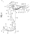
- FIG. 4 is a diagram schematically illustrating a state where the other end portion of the transport path member of the automatic document feeder according to this exemplary embodiment is supported at a second open position.
- An image forming apparatus 100 includes an image recording apparatus 110 recording an image on a recording medium P such as a sheet of paper and an image reading apparatus 10 reading an image of an original document.
- the image reading apparatus 10 is disposed in the upper part of the image forming apparatus 100 and serves to read an image of an original document and to convert the read image into an image signal.
- the image recording apparatus 110 is disposed in the lower part of the image forming apparatus 100 and serves to record an image on a recording medium P on the basis of the image signal converted by the image reading apparatus 10 .
- the configuration of the image recording apparatus 110 will be first described below.
- the image recording apparatus 110 includes plural recording medium storage sections 130 storing recording mediums P such as sheets of paper having different sizes, an image forming section 120 forming a toner image on a recording medium P, a transport section 148 transporting a recording medium P to the image forming section 120 from the recording medium storage sections 130 , a fixing device 136 fixing the toner image formed by the image forming section 120 to the recording medium P, and a recording medium discharge section 140 to which the recording medium P to which the toner image is fixed by the fixing device 136 is discharged.
- recording mediums P such as sheets of paper having different sizes
- an image forming section 120 forming a toner image on a recording medium P
- a transport section 148 transporting a recording medium P to the image forming section 120 from the recording medium storage sections 130
- a fixing device 136 fixing the toner image formed by the image forming section 120 to the recording medium P
- a recording medium discharge section 140 to which the recording medium P to which the toner image is fixed by the fixing device 136 is discharge
- the image forming section 120 includes image forming units 122 Y, 122 M, 122 C, and 122 K forming color toner images of yellow (Y), magenta (M), cyan (C), and black (K), an intermediate transfer belt 124 as an example of an intermediate transfer member to which the toner images formed by the image forming units 122 Y, 122 M, 122 C, and 122 K are transferred, primary transfer rolls 126 as an example of a primary transfer member that transfers the toner images formed by the image forming units 1221 , 122 M, 122 C, and 122 K to the intermediate transfer belt 124 , and a secondary transfer roll 128 as an example of a secondary transfer member that transfers the toner images transferred to the intermediate transfer belt 124 to a recording medium P.
- the image forming units 122 Y, 122 M, 122 C, and 122 K each have a photoreceptor drum 112 that rotates in one direction (the direction of arrow A in FIG. 1 ) as an image supporting member supporting a formed image.
- each photoreceptor drum 112 a charging device 114 charging the photoreceptor drum 112 , an exposing device 116 exposing the charged photoreceptor drum 112 to form an electrostatic latent image on the photoreceptor drum 112 , a developing device 118 developing the electrostatic latent image formed on the photoreceptor drum 112 to form a toner image, and a cleaning device 144 removing the toner remaining on the surface of the photoreceptor drum 112 after the toner image is transferred to the intermediate transfer belt 124 are sequentially provided from the upstream side in the rotation direction of the photoreceptor drum 112 .
- the intermediate transfer belt 124 is supported by a backup roll 134 opposed to the secondary transfer roll 128 and a support roll 146 and circulates in one direction (the clockwise direction in FIG. 1 ) in contact with the photoreceptor drum 112 .
- Each primary transfer roll 126 is opposed to the corresponding photoreceptor drum 112 with the intermediate transfer belt 124 interposed therebetween.
- a primary transfer position at which a toner image formed on the photoreceptor drum 112 is primarily transferred to the intermediate transfer belt 124 is formed between the primary transfer roll 126 and the photoreceptor drum 112 .
- the secondary transfer roll 128 is opposed to the backup roll 134 with the intermediate transfer belt 124 interposed therebetween.
- a secondary transfer position at which the toner images primarily transferred to the intermediate transfer belt 124 are secondarily transferred to a recording medium P is formed between the secondary transfer roll 128 and the backup roll 134 .
- the transport section 148 includes a pickup roll 132 picking up and sending a recording medium P stored in the recording medium storage section 130 and a pair of transport rolls 142 transporting the recording medium P picked up by the pickup roll 132 to the secondary transfer position.
- the fixing device 136 is disposed downstream in the transport direction about the secondary transfer position and serves to fix the toner images transferred at the secondary transfer position to the recording medium P.
- a pair of discharge rolls 138 discharging the recording medium P to the recording medium discharge section 140 is disposed downstream in the transport direction about the fixing device 136 .
- a recording medium P picked up from the recording medium storage section 130 is first transported to the secondary transfer position by the pair of transport rolls 142 .
- color toner images formed by the image forming units 122 Y, 122 M, 122 C, and 122 K are superimposed on the intermediate transfer belt 124 to form a color image.
- the color image formed on the intermediate transfer belt 124 is transferred to the recording medium P transported to the secondary transfer position.
- the recording medium P to which the toner image is transferred is transported to the fixing device 136 and the transferred toner image is fixed by the fixing device 136 .
- the recording medium P to which the toner image is fixed is discharged to the recording medium discharge section 140 by the pair of discharge rolls 138 . In this way, a series of image forming operations is performed.
- the configuration of the image recording apparatus 110 is not limited to this configuration, but a direct transfer type image recording apparatus not having an intermediate transfer member, or an inkjet type image recording apparatus, or an image recording apparatus capable of recording an image with a configuration other than the above-mentioned configuration may be employed.
- the configuration of the image reading apparatus 10 according to this exemplary embodiment will be described below.
- the image reading apparatus 10 according to this exemplary embodiment is configured to be able to read both an original document under transport and a stationary original document.
- the image reading apparatus 10 includes an automatic document feeder 12 having built therein a front side reading mechanism 70 reading an image on the front side of an original document under transport and an image on the front side of a stationary original document and a back side reading mechanism 94 reading an image on the back side of the original document under transport and a processing device 92 processing an image signal of the image read by the front side reading mechanism 70 or the back side reading mechanism 94 .
- the front side reading mechanism 70 will be described below.
- the front side reading mechanism 70 is disposed in the lower part of the image reading apparatus 10 .
- the front side reading mechanism 70 includes a first glass platen 72 as an example of a platform member on which an original document from which an image should be read in a stationary state is placed and a second glass platen 74 as an example of a transmissive member transmitting light applied to the original document under transport.
- the front side reading mechanism 70 includes a first moving member 76 and a second moving member 78 which can move along the first glass platen 72 .
- the first moving member 76 is provided with a light-emitting portion 80 emitting light to an original document and a first mirror 82 receiving reflected light reflected by the original document.
- the second moving member 78 is provided with a second mirror 84 and a third mirror 86 guiding the light acquired from the first mirror 82 .
- the front side reading mechanism 70 further includes a focusing lens 88 optically reducing the optical image acquired from the third mirror 86 and a CCD (Charge Coupled Device) image sensor 90 photoelectrically converting the optical image focused by the focusing lens 88 .
- a focusing lens 88 optically reducing the optical image acquired from the third mirror 86
- a CCD (Charge Coupled Device) image sensor 90 photoelectrically converting the optical image focused by the focusing lens 88 .
- the image signal acquired by the CCD image sensor 90 is sent to the exposing device 116 by the processing device 92 .
- the first moving member 76 and the second moving member 78 move in the scanning direction (the direction of arrow B), for example, at a ratio of 2:1.
- the light from the light-emitting portion 80 of the first moving member 76 is applied to a surface to be read of the original document and the reflected light from the original document is reflected sequentially by the first mirror 82 , the second mirror 84 , and the third mirror 86 , and is then guided to the focusing lens 88 .
- the light guided to the focusing lens 88 forms an image on the light-receiving surface of the CCD image sensor 90 .
- the CCD image sensor 90 is a one-dimensional sensor and simultaneously processes one line.
- the first moving member 76 is made to move in the direction (the sub scanning direction) perpendicular to the main scanning direction and the next line of the original document is read. By repeatedly performing this operation over the entire size of the original document, the reading of a page of the original document is ended.
- the original document transported by the automatic document feeder 12 passes over the second glass platen 74 .
- the first moving member 76 and the second moving member 78 are stopped at the position indicated by the solid line in FIG. 1 .
- the reflected light of the first line of the original document is reflected by the first mirror 82 , the second mirror 84 , and the third mirror 86 , is focused by focusing lens 88 , and an image is then read by the CCD image sensor 90 .
- one line in the main scanning direction is simultaneously processed by the CCD image sensor 90 which is a one-dimensional sensor and then the next line of the original document transported by the automatic document feeder 12 in the main scanning direction is read. That is, by causing the original document to pass through the reading position on the second glass platen 74 after the leading edge of the original document reaches the reading position on the second glass platen 74 , the reading of a page of the original document in the sub scanning direction is ended.
- the back side reading mechanism 94 is built in the automatic document feeder 12 and includes an image sensor 96 as an example of a reading unit including a reading plane 96 A opposing a transport path surface 38 of a transport path member 40 to be described later so as to read an image of (the back side) of an original document.
- the image sensor 96 optically reads the image of an original document by irradiating the original document with light from a light-emitting portion such as a light-emitting diode and receiving the reflected light by the use of a light-receiving portion.
- the configuration of the automatic document feeder 12 will be described below.
- the automatic document feeder 12 is disposed in the upper part of the image reading apparatus 10 and serves to automatically transport an original document so as to read the original document by the use of the front side reading mechanism 70 and the back side reading mechanism 94 .
- a hinge portion (not shown in the drawings) is disposed on the deep side of the drawing surface of FIG. 1 and the part just close to the drawing surface of FIG. 1 can move vertically about the hinge portion, that is, the first glass platen 72 and the second glass platen 74 can be opened and closed.
- the automatic document feeder 12 includes a document platform 14 as an example of a document storage section in which an original document can be stored and placed, a transport section 20 transporting the original document placed on the document platform 14 to a document discharge section 18 to be described later, and a document discharge section 18 to which the original document transported through the transport path 30 in the transport section 20 is discharged.
- the document platform 14 is provided with a lifting mechanism 16 lifting up and down the document platform 14 .
- the lifting mechanism 16 lifts up the document platform 14 up to the position at which an original document contacts a pickup roll 22 to be described later when the original document is placed on the document platform 14 .
- the transport section 20 includes a pickup roll 22 picking up an original document from the document platform 14 , a transport path 30 through which the original document picked up from the document platform 14 is transported, plural transport rolls 24 transporting the original document along the transport path 30 , a counter member 26 opposed to the second glass platen 74 disposed in the transport path 30 , and a discharge roll 28 discharging the original document to the document discharge section 18 .
- a transport path member 40 including a transport path surface 38 constituting a part of the transport path 30 is disposed in the lower part of the automatic document feeder 12 opposed to the first glass platen 72 and the second glass platen 74 .
- the transport path member 40 has a substantially trapezoidal shape which is flat in a side view and the top surface thereof serves as the transport path surface 38 .
- one end portion 40 A which is on the downstream side (the discharge roll 28 side) in the document transport direction is rotatably supported by the feeder body 12 A of the automatic document feeder 12 .
- a spindle 32 formed in the feeder body 12 A is inserted into a through-hole (not shown) formed in the end portion 40 A of the transport path member 40 .
- the other end portion 40 B of the transport path member 40 is supported to be movable in the vertical direction about the spindle 32 and can open a part of the transport path 30 by moving (rotating) downward in the direction in which the other end portion gets away from the feeder body 12 A.
- the side wall portion 42 on the opening side (the side close to the drawing surface of FIG. 1 ) of the automatic document feeder 12 is provided with a hook member 44 as an example of a locking member and a lever member 46 as an example of an operation member.
- the hook member 44 and the lever member 46 are attached to the rotation shaft 48 rotatably disposed in the other end portion 40 B which is on the upstream side in the document transport direction of the transport path member 40 and rotate together.
- annular portion 44 A is incorporated into the lower end portion of the hook member 44 and the annular portion 44 A is inserted into and fixed to the rotation shaft 48 .
- An annular portion 46 A is incorporated into the upper end portion of the lever member 46 and the annular portion 46 A is inserted into and fixed to the rotation shaft 48 .
- the hook member 44 is normally impelled in the direction (in the clockwise direction in the drawing) in which it is locked to a locking portion 34 as an example of a portion to be locked disposed in the feeder body 12 A by the use of an impelling member such as a torsion spring not shown.
- the hook member 44 is normally locked to the locking portion 34 when the transport path 30 shown in FIG. 2 is closed (by the transport path member 40 ).
- the hook member rotates in the same direction along with the rotating operation of the lever member 46 in the downward direction (in the counterclockwise direction in the drawing) about the rotation shaft 48 , which is indicated by a virtual line in FIG. 2 , whereby the hook member is unlocked from the locking portion 34 .
- the locked state (the state where the transport path 30 is closed) of the transport path member 40 is released.
- the other end portion 40 B of the transport path member 40 can move downward to open the transport path 30 .
- the opposite side wall portion is provided with only a hook member 44 that is normally impelled in the direction in which it is locked to the locking portion 34 and that is unlocked from the locking portion 34 by interlocking with the hook member 44 of the side wall portion 42 with the rotating operation of the lever member 46 and is not provided with the lever member 46 .
- the side wall portion 42 of the transport path member 40 is provided with a link member 50 as an example of a support member including a portion to be locked 54 which contacts the locking portion 36 of the feeder body 12 A to regulate the movement thereof when the other end portion 40 B of the transport path member 40 moves downward about the spindle 32 .
- the link member 50 includes a thin plate-like base portion 52 and a thick plate-like portion to be locked 54 incorporated into the base portion 52 in the thickness direction thereof and can rotate relative to the transport path member 40 coaxially therewith.
- an annular portion 56 is formed at an end portion of the link member 50 , and the annular portion 56 is relative-rotatably inserted into a cylindrical boss portion 45 protruding around a through-hole of the transport path member 40 .
- a hook-like attachment portion 58 is formed at the other end opposite to the annular portion 56 .
- An end of a coil spring 60 as an example of an impelling member is attached to the attachment portion 58 and the other end of the coil spring 60 is attached to an attachment portion 47 disposed in the other end portion 40 B in the side wall portion 42 of the transport path member 40 , that is, at a position adjacent to the rotation shaft 48 .
- a protrusion 43 to be described later is normally impelled in the direction (in the clockwise direction in the drawing) in which it contacts a stopper 53 by the coil spring 60 . That is, a stopper 53 as an example of a regulating portion protruding in a flat panel shape in the thickness direction is formed in the part just below the attachment portion 58 of the link member 50 (the base portion 52 ).
- a protrusion 43 as an example of a portion to be regulated that is impelled in the clockwise direction in the drawing by the coil spring 60 to contact the stopper 53 is formed in the side wall portion 42 of the transport path member 40 .
- the protrusion 43 is formed in a rib shape coming in vertical contact (linear contact) with the stopper 53 , and the relative rotation of the other end portion 408 of the transport path member 40 in the direction in which it gets close to the feeder body 12 A is regulated by the protrusion 43 .
- the automatic document feeder 12 including the transport path member 40 having the above-mentioned configuration will be described below.
- the original document is transported by the automatic document feeder 12 .
- the original document on the document platform 14 is picked up and sent to the transport path 30 by the pickup roll 22 , the original document picked up and sent to the transport path 30 is transported along the transport path 30 by the plural transport rolls 24 , and an image recorded on the front side of the original document is read by the front side reading mechanism 70 while passing over the second glass platen 74 .
- the image on the back side thereof is read by the back side reading mechanism 94 while transporting the original document over the transport path surface 38 .
- the original document of which at least the image on the front side is read in this way is discharged to the document discharge section 18 by the discharge roll 28 .
- the part of the automatic document feeder 12 close to the drawing surface is lifted up about the hinge portion on the deep side to expose the lever member 46 .
- the lever member 46 is then operated to rotate downward.
- a pair of hook members 44 is unlocked from the locking portion 34 of the feeder body 12 A, and the other end portion 40 B of the transport path member 40 moves downward with its weight about the spindle 32 of the end portion 40 A to open the transport path 30 (the transport path surface 38 ) as shown in FIG. 3 .
- the portion 54 to be locked of the link member 50 contacts the locking portion 36 of the feeder body 12 A to regulate the downward movement of the other end portion 40 B of the transport path member 40 . That is, the link member 50 having the portion to be locked 54 locked to the locking portion 36 supports the other end portion 40 B of the transport path member 40 by causing the protrusion 43 to contact the stopper 53 by the use of the coil spring 60 , that is, with the impelling force of the coil spring 60 . Accordingly, the other end portion 40 B of the transport path member 40 is supported at the first open position shown in FIG. 3 and the original document staying on the transport path surface 38 can be removed.
- the other end portion 40 B (for example, the lever member 46 ) of the transport path member 40 supported at the first open position is pressed with a finger (a force in the opening direction is applied) so as to further move downward (in the counterclockwise direction in the drawing).
- the link member 50 is configured to be rotatable relative to the transport path member 40 , the other end portion 40 B of the transport path member 40 further moves downward (in the counterclockwise direction in the drawing) against the impelling force of the coil spring 60 (the coil spring 60 expands) in the state where the portion 54 to be locked of the link member 50 is locked to the locking portion 36 , as shown in FIG. 4 .
- the protrusion 43 gets away from the stopper 53 .
- the other end portion 40 B of the transport path member 40 is supported at the second open position at which the opening angle is larger than at the first open position and the transport path 30 is opened larger than at the first open position. Therefore, it is possible to remove the original document staying on the transport path surface 38 more easily than at the first open position. That is, it is possible to improve the maintainability of the automatic document feeder 12 .
- the reading plane 96 A of the image sensor 96 of the back side reading mechanism 94 can be exposed to be visible from the direction perpendicular to the opening surface 12 B of the feeder body 12 A which is opened with the downward movement of the transport path member 40 . Accordingly, it is possible to facilitate the cleaning of the reading plane 96 A (the maintenance of the image sensor 96 ) and to further improve the maintainability of the automatic document feeder 12 .
- the reading plane 96 A of the image sensor 96 is not visible from the direction perpendicular to the opening surface 12 B and it is thus difficult to insert a finger up to the reading plane 96 A.
- the other end portion 40 B of the transport path member 40 can be opened to the second open position, it is easy to insert a finger up to the reading plane 96 A and it is possible to easily perform the cleaning of the reading plane 96 A (the maintenance of the image sensor 96 ).
- the transport path 30 When it is intended to close the transport path 30 (the transport path surface 38 ) by the use of the transport path member 40 , the other end portion 40 B of the transport path member 40 is manually made to move up. Then, since a pair of hook members 44 is impelled in the direction in which they are normally locked to the locking portion 34 , the hook members are automatically locked to the locking portions 34 . Accordingly, the transport path 30 is closed.
- the automatic document feeder 12 and the image forming apparatus 100 according to this exemplary embodiment have been described with reference to the accompanying drawings, the automatic document feeder 12 and the image forming apparatus 100 according to this exemplary embodiment are not limited to the configurations shown in the drawing, but may be modified, changed, and improved in various forms.
- the link member 50 and the coil spring 60 are not limited to the configuration in which they are disposed in only the side wall portion 42 of the transport path member 40 , but may be disposed in the opposite side wall portion thereof.
- the front side reading mechanism 70 and the back side reading mechanism 94 are not limited to the above-mentioned configuration, but may have other configurations capable of reading an image of an original document.
Landscapes
- Engineering & Computer Science (AREA)
- Multimedia (AREA)
- Signal Processing (AREA)
- Physics & Mathematics (AREA)
- General Physics & Mathematics (AREA)
- Mechanical Engineering (AREA)
- Facsimiles In General (AREA)
- Exposure Or Original Feeding In Electrophotography (AREA)
- Facsimile Scanning Arrangements (AREA)
- Electrophotography Configuration And Component (AREA)
- Delivering By Means Of Belts And Rollers (AREA)
Abstract
Description
Claims (4)
Applications Claiming Priority (2)
| Application Number | Priority Date | Filing Date | Title |
|---|---|---|---|
| JP2011-221373 | 2011-10-05 | ||
| JP2011221373A JP5879891B2 (en) | 2011-10-05 | 2011-10-05 | Automatic document feeder and image forming apparatus |
Publications (2)
| Publication Number | Publication Date |
|---|---|
| US20130088762A1 US20130088762A1 (en) | 2013-04-11 |
| US8625174B2 true US8625174B2 (en) | 2014-01-07 |
Family
ID=48017491
Family Applications (1)
| Application Number | Title | Priority Date | Filing Date |
|---|---|---|---|
| US13/438,573 Expired - Fee Related US8625174B2 (en) | 2011-10-05 | 2012-04-03 | Automatic document feeder and image forming apparatus |
Country Status (4)
| Country | Link |
|---|---|
| US (1) | US8625174B2 (en) |
| JP (1) | JP5879891B2 (en) |
| KR (1) | KR101555248B1 (en) |
| CN (1) | CN103030007B (en) |
Cited By (1)
| Publication number | Priority date | Publication date | Assignee | Title |
|---|---|---|---|---|
| US20140153070A1 (en) * | 2012-11-30 | 2014-06-05 | Kyocera Document Solutions Inc. | Image reading apparatus and image forming apparatus |
Families Citing this family (9)
| Publication number | Priority date | Publication date | Assignee | Title |
|---|---|---|---|---|
| JP6435873B2 (en) | 2015-01-21 | 2018-12-12 | 富士ゼロックス株式会社 | Image reading apparatus and image forming apparatus |
| CN105163000B (en) * | 2015-09-22 | 2019-11-12 | 许昌学院 | An all-in-one machine for automatic page turning, scanning and copying |
| JP7013202B2 (en) * | 2017-10-25 | 2022-01-31 | キヤノン株式会社 | Sheet transfer device, image forming device and image forming system |
| JP6942619B2 (en) * | 2017-12-06 | 2021-09-29 | キヤノン株式会社 | Sheet processing equipment |
| WO2020222814A1 (en) | 2019-04-30 | 2020-11-05 | Hewlett-Packard Development Company, L.P. | Automatic document feeder with automated media tray extender |
| US11827480B2 (en) | 2019-07-31 | 2023-11-28 | Hewlett-Packard Development Company, L.P. | Automatic document feeder with automated media tray |
| WO2021025665A1 (en) * | 2019-08-02 | 2021-02-11 | Hewlett-Packard Development Company, L.P. | Rotatable media ramp for automatic document feeder |
| JP2022125896A (en) * | 2021-02-17 | 2022-08-29 | 富士フイルムビジネスイノベーション株式会社 | Conveying device and image forming apparatus |
| JP7679675B2 (en) | 2021-04-09 | 2025-05-20 | ブラザー工業株式会社 | Reading device |
Citations (3)
| Publication number | Priority date | Publication date | Assignee | Title |
|---|---|---|---|---|
| JP4331668B2 (en) | 2004-11-11 | 2009-09-16 | シャープ株式会社 | Document reader |
| US8064109B2 (en) * | 2007-03-26 | 2011-11-22 | Brother Kogyo Kabushiki Kaisha | Image reader and image forming apparatus |
| US8395827B2 (en) * | 2008-11-11 | 2013-03-12 | Avision Inc. | Automatic sheet-feeding scanner having non-linear paper path |
Family Cites Families (13)
| Publication number | Priority date | Publication date | Assignee | Title |
|---|---|---|---|---|
| JPH01221978A (en) * | 1988-02-29 | 1989-09-05 | Pfu Ltd | Image reader automatic reading unit |
| JPH0844131A (en) * | 1994-07-28 | 1996-02-16 | Ricoh Co Ltd | Image forming device |
| JP3411438B2 (en) * | 1996-03-01 | 2003-06-03 | 株式会社リコー | Automatic document feeder |
| JP3245059B2 (en) * | 1996-06-28 | 2002-01-07 | 京セラミタ株式会社 | Automatic document feeder |
| JPH1026922A (en) * | 1996-07-10 | 1998-01-27 | Mita Ind Co Ltd | Open/close mechanism |
| JPH1063163A (en) * | 1996-08-13 | 1998-03-06 | Ricoh Co Ltd | Recording device |
| JPH10236689A (en) * | 1997-02-28 | 1998-09-08 | Fuji Xerox Co Ltd | Document carrying device |
| JP3825931B2 (en) | 1999-02-12 | 2006-09-27 | キヤノン株式会社 | Automatic document feeder and image forming apparatus |
| JP3949474B2 (en) | 2002-03-08 | 2007-07-25 | 株式会社リコー | Sheet conveying apparatus and image forming apparatus |
| JP2004277144A (en) * | 2003-03-18 | 2004-10-07 | Ricoh Co Ltd | Document feeder and image forming apparatus |
| KR100644712B1 (en) * | 2005-10-10 | 2006-11-10 | 삼성전자주식회사 | Jam Processing Structure of Image Forming Device |
| US7710614B2 (en) * | 2005-10-26 | 2010-05-04 | Kyocera Mita Corporation | Image forming device |
| JP4999713B2 (en) * | 2007-01-26 | 2012-08-15 | キヤノン株式会社 | Sheet conveying apparatus and image forming apparatus |
-
2011
- 2011-10-05 JP JP2011221373A patent/JP5879891B2/en not_active Expired - Fee Related
-
2012
- 2012-04-03 US US13/438,573 patent/US8625174B2/en not_active Expired - Fee Related
- 2012-05-08 KR KR1020120048480A patent/KR101555248B1/en active Active
- 2012-05-08 CN CN201210141360.4A patent/CN103030007B/en active Active
Patent Citations (3)
| Publication number | Priority date | Publication date | Assignee | Title |
|---|---|---|---|---|
| JP4331668B2 (en) | 2004-11-11 | 2009-09-16 | シャープ株式会社 | Document reader |
| US8064109B2 (en) * | 2007-03-26 | 2011-11-22 | Brother Kogyo Kabushiki Kaisha | Image reader and image forming apparatus |
| US8395827B2 (en) * | 2008-11-11 | 2013-03-12 | Avision Inc. | Automatic sheet-feeding scanner having non-linear paper path |
Cited By (2)
| Publication number | Priority date | Publication date | Assignee | Title |
|---|---|---|---|---|
| US20140153070A1 (en) * | 2012-11-30 | 2014-06-05 | Kyocera Document Solutions Inc. | Image reading apparatus and image forming apparatus |
| US8824028B2 (en) * | 2012-11-30 | 2014-09-02 | Kyocera Document Solutions Inc. | Image reading apparatus and image forming apparatus |
Also Published As
| Publication number | Publication date |
|---|---|
| CN103030007A (en) | 2013-04-10 |
| JP5879891B2 (en) | 2016-03-08 |
| KR20130037148A (en) | 2013-04-15 |
| KR101555248B1 (en) | 2015-09-23 |
| JP2013080189A (en) | 2013-05-02 |
| US20130088762A1 (en) | 2013-04-11 |
| CN103030007B (en) | 2016-01-13 |
Similar Documents
| Publication | Publication Date | Title |
|---|---|---|
| US8625174B2 (en) | Automatic document feeder and image forming apparatus | |
| JP7563155B2 (en) | Document conveying device, image reading device and image forming device | |
| JP5873848B2 (en) | Sheet feeding apparatus and image forming apparatus provided with the same | |
| US8579282B2 (en) | Image forming apparatus | |
| JP4501990B2 (en) | Sheet conveying apparatus and image forming apparatus | |
| JP5688929B2 (en) | Image reading apparatus and image forming apparatus having the same | |
| US20170134598A1 (en) | Image forming apparatus incorporating automatic coupling device | |
| JP2016088645A (en) | Sheet transport device | |
| JP6273922B2 (en) | Automatic document feeder, image reading apparatus, and image forming apparatus | |
| CN103662883A (en) | Sheet conveying device, image reading apparatus and image forming apparatus provided with same | |
| US8928953B2 (en) | Image reading device and image forming apparatus therewith using a pair of rail portions to support the optical unit slidable in the sub scanning direction | |
| JP5823454B2 (en) | Paper feeding device and image forming apparatus | |
| US8511670B2 (en) | Sheet conveying device, image reader, and image forming apparatus | |
| KR101597144B1 (en) | Automatic document feeder | |
| JP2012220546A (en) | Image forming device | |
| JP5881636B2 (en) | Sheet feeding apparatus and image forming apparatus provided with the same | |
| CN105282377A (en) | Scanner device and image forming apparatus including the same | |
| JP4700829B2 (en) | Image forming apparatus | |
| JP2010184804A (en) | Sheet material separating device, paper feeder, and image forming device | |
| JP7625963B2 (en) | SHEET DISCHARGE DEVICE, DOCUMENT CONVEYING DEVICE, AND IMAGE FORMING APPARATUS EQUIPPED WITH SAME | |
| JP5779574B2 (en) | Recording medium storage cassette and image forming apparatus having the same | |
| JP2010163278A (en) | Sheet storing device | |
| JP2009173372A (en) | Manual paper feed mechanism and image forming device having the same | |
| JP2005070070A (en) | Image forming apparatus | |
| JP2019089610A (en) | Sheet discharge apparatus and image reading apparatus |
Legal Events
| Date | Code | Title | Description |
|---|---|---|---|
| AS | Assignment |
Owner name: FUJI XEROX CO., LTD., JAPAN Free format text: ASSIGNMENT OF ASSIGNORS INTEREST;ASSIGNORS:YAMAZAKI, AKIRA;HA, HYUNDEOK;CHO, SENGGYU;REEL/FRAME:027992/0555 Effective date: 20120326 |
|
| STCF | Information on status: patent grant |
Free format text: PATENTED CASE |
|
| FPAY | Fee payment |
Year of fee payment: 4 |
|
| MAFP | Maintenance fee payment |
Free format text: PAYMENT OF MAINTENANCE FEE, 8TH YEAR, LARGE ENTITY (ORIGINAL EVENT CODE: M1552); ENTITY STATUS OF PATENT OWNER: LARGE ENTITY Year of fee payment: 8 |
|
| AS | Assignment |
Owner name: FUJIFILM BUSINESS INNOVATION CORP., JAPAN Free format text: CHANGE OF NAME;ASSIGNOR:FUJI XEROX CO., LTD.;REEL/FRAME:058287/0056 Effective date: 20210401 |
|
| FEPP | Fee payment procedure |
Free format text: MAINTENANCE FEE REMINDER MAILED (ORIGINAL EVENT CODE: REM.); ENTITY STATUS OF PATENT OWNER: LARGE ENTITY |
|
| LAPS | Lapse for failure to pay maintenance fees |
Free format text: PATENT EXPIRED FOR FAILURE TO PAY MAINTENANCE FEES (ORIGINAL EVENT CODE: EXP.); ENTITY STATUS OF PATENT OWNER: LARGE ENTITY |
|
| STCH | Information on status: patent discontinuation |
Free format text: PATENT EXPIRED DUE TO NONPAYMENT OF MAINTENANCE FEES UNDER 37 CFR 1.362 |
|
| FP | Lapsed due to failure to pay maintenance fee |
Effective date: 20260107 |