US8625036B2 - 3D glasses and 3D video playing apparatus - Google Patents

3D glasses and 3D video playing apparatus Download PDF

Info

Publication number
US8625036B2
US8625036B2 US13/377,547 US201113377547A US8625036B2 US 8625036 B2 US8625036 B2 US 8625036B2 US 201113377547 A US201113377547 A US 201113377547A US 8625036 B2 US8625036 B2 US 8625036B2
Authority
US
United States
Prior art keywords
wave phase
phase plate
glasses
polarizer
quarter
Prior art date
Legal status (The legal status is an assumption and is not a legal conclusion. Google has not performed a legal analysis and makes no representation as to the accuracy of the status listed.)
Expired - Fee Related, expires
Application number
US13/377,547
Other versions
US20130027619A1 (en
Inventor
Chia-Chiang Hsiao
Chih-Wen Chen
Chengming He
Current Assignee (The listed assignees may be inaccurate. Google has not performed a legal analysis and makes no representation or warranty as to the accuracy of the list.)
TCL China Star Optoelectronics Technology Co Ltd
Original Assignee
Shenzhen China Star Optoelectronics Technology Co Ltd
Priority date (The priority date is an assumption and is not a legal conclusion. Google has not performed a legal analysis and makes no representation as to the accuracy of the date listed.)
Filing date
Publication date
Priority claimed from CN2011202670813U external-priority patent/CN202275245U/en
Application filed by Shenzhen China Star Optoelectronics Technology Co Ltd filed Critical Shenzhen China Star Optoelectronics Technology Co Ltd
Assigned to SHENZHEN CHINA STAR OPTOELECTRONICS TECHNOLOGY CO., LTD. reassignment SHENZHEN CHINA STAR OPTOELECTRONICS TECHNOLOGY CO., LTD. ASSIGNMENT OF ASSIGNORS INTEREST (SEE DOCUMENT FOR DETAILS). Assignors: HE, CHENGMING, CHEN, CHIH-WEN, HSIAO, CHIA-CHIANG
Publication of US20130027619A1 publication Critical patent/US20130027619A1/en
Application granted granted Critical
Publication of US8625036B2 publication Critical patent/US8625036B2/en
Expired - Fee Related legal-status Critical Current
Adjusted expiration legal-status Critical

Links

Images

Classifications

    • GPHYSICS
    • G02OPTICS
    • G02BOPTICAL ELEMENTS, SYSTEMS OR APPARATUS
    • G02B30/00Optical systems or apparatus for producing three-dimensional [3D] effects, e.g. stereoscopic images
    • G02B30/20Optical systems or apparatus for producing three-dimensional [3D] effects, e.g. stereoscopic images by providing first and second parallax images to an observer's left and right eyes
    • G02B30/22Optical systems or apparatus for producing three-dimensional [3D] effects, e.g. stereoscopic images by providing first and second parallax images to an observer's left and right eyes of the stereoscopic type
    • G02B30/25Optical systems or apparatus for producing three-dimensional [3D] effects, e.g. stereoscopic images by providing first and second parallax images to an observer's left and right eyes of the stereoscopic type using polarisation techniques
    • GPHYSICS
    • G02OPTICS
    • G02BOPTICAL ELEMENTS, SYSTEMS OR APPARATUS
    • G02B30/00Optical systems or apparatus for producing three-dimensional [3D] effects, e.g. stereoscopic images
    • G02B30/20Optical systems or apparatus for producing three-dimensional [3D] effects, e.g. stereoscopic images by providing first and second parallax images to an observer's left and right eyes
    • G02B30/22Optical systems or apparatus for producing three-dimensional [3D] effects, e.g. stereoscopic images by providing first and second parallax images to an observer's left and right eyes of the stereoscopic type
    • G02B30/24Optical systems or apparatus for producing three-dimensional [3D] effects, e.g. stereoscopic images by providing first and second parallax images to an observer's left and right eyes of the stereoscopic type involving temporal multiplexing, e.g. using sequentially activated left and right shutters

Definitions

  • the present disclosure relates to the technical field of displaying, and more particularly, to a pair of 3D glasses and a 3D video playing apparatus.
  • 3D videos are attracting more and more attentions.
  • the 3D videos are greatly favored by many consumers as they can provide a real-world feeling and a visual impact when being played.
  • the most common device for achieving the 3D effect in the market is a kind of light gate glasses, whose two glasses are installed with a light gate respectively.
  • the two light gates are opened and closed alternately in such a way that when one of the two light gates is opened, the other is closed.
  • one image can be seen by only one eye.
  • the image in the eye will not disappear so long as a time interval during which the same glass is closed is less than 0.15 s. In this way, although the image is not seen by this eye, the image still persists in the brain, so a 3D image can be composed in the brain.
  • the primary objective of the present disclosure is to provide a pair of 3D glasses and a 3D video playing apparatus in order to overcome the technical shortcoming of a decreased luminance of an image or even failure to form an image, which due to an inclined angle included between a 3D display device and the pair of 3D glasses.
  • the pair of 3D glasses further comprises a second half-wave phase plate which is disposed between the second quarter-wave phase plate and the liquid crystal layer and matches with the liquid crystal layer.
  • the present disclosure further provides a 3D video playing apparatus, which comprises a 3D display device and the pair of 3D glasses as described above.
  • the 3D display device comprises a liquid crystal display (LCD), a first polarizer and a first quarter-wave phase plate.
  • a surface of the first polarizer abuts on a light exiting surface of the LCD.
  • the first polarizer matches with the light exiting surface of the LCD.
  • the first quarter-wave phase plate is disposed on the other surface of the first polarizer and matches with the light exiting surface of the LCD.
  • the pair of 3D glasses is located at the side of the light exiting surface of the 3D display device and in a light path of the 3D display device with the second quarter-wave phase plates of the pair of 3D glasses facing towards the light exiting surface of the 3D display device.
  • the pair of 3D glasses further comprises a second half-wave phase plate that is disposed between the second quarter-wave phase plate and the liquid crystal layer and matches with the liquid crystal layer.
  • a polarizing axis of the first half-wave phase plate and a transmittance axis of the first polarizer include an angle of ⁇ 1 there between
  • a polarizing axis of the first quarter-wave phase plate and the transmittance axis of the first polarizer include an angle of 2 ⁇ 1 +45° there between.
  • a polarizing axis of the second half-wave phase plate and an absorbance axis of the second polarizer include an angle of ⁇ 2 there between
  • a polarizing axis of the second quarter-wave phase plate and the absorbance axis of the second polarizer include an angle of ⁇ 2 ⁇ 2 ⁇ 45° there between.
  • a half-wave phase plate (comprising a first half-wave phase plate and a second half-wave phase plate) is provided at the end of the 3D display device and/or the end of the pair of 3D glasses, which can effectively solve the problem of dispersion caused by the aforesaid quarter-wave phase plates.
  • FIG. 1 is a schematic structural view of a 3D video playing apparatus in the prior art
  • FIG. 2 is a schematic structural view of a first embodiment of a 3D display device according to the present disclosure
  • FIG. 3 is a schematic structural view of a second embodiment of the 3D display device according to the present disclosure.
  • FIG. 4 is a schematic structural view of a first embodiment of glasses of a pair of 3D glasses according to the present disclosure
  • FIG. 6 is a schematic structural view of a first embodiment of a 3D video playing apparatus according to the present disclosure.
  • FIG. 8 is a schematic structural view of a third embodiment of the 3D video playing apparatus according to the present disclosure.
  • FIG. 9 is a schematic structural view of a fourth embodiment of the 3D video playing apparatus according to the present disclosure.
  • the present disclosure relates to a 3D display device 10 .
  • FIG. 2 there is shown a schematic structural view of a first embodiment of the 3D display device 10 according to the present disclosure.
  • FIG. 3 there is shown a schematic structural view of a second embodiment of the 3D display device 10 according to the present disclosure.
  • a first half-wave phase plate 14 is additionally provided to solve the problem of dispersion which caused by the first quarter-wave phase plate 13 .
  • a second half-wave phase plate 24 described below has the same working principle and function as the first half-wave phase plate 14 .
  • the pair of 3D glasses is used with the 3D display device 10 .
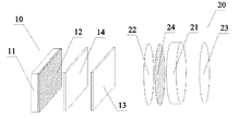
  • the pair of 3D glasses comprises a left glass 20 and a right glass 20 in symmetry with each other.
  • Each of the glasses 20 comprises a second quarter-wave phase plate 22 , a liquid crystal layer 21 and a second polarizer 23 .
  • the second quarter-wave phase plate 22 and the second polarizer 23 are located at two sides of the liquid crystal layer 21 respectively.
  • the second quarter-wave phase plate 22 and the second polarizer 23 match with the liquid crystal layer 21 in both size and shape.
  • a surface of the second quarter-wave phase plate 22 shall face towards the light exiting surface of the 3D display device 10 .
  • FIG. 5 there is shown a schematic structural view of a second embodiment of the glasses of the pair of 3D glasses according to the present disclosure.
  • each of the glasses of this embodiment further comprises a second half-wave phase plate 24 , which is disposed between the second quarter-wave phase plate 22 and the liquid crystal layer 21 and matches with the liquid crystal layer 21 in terms of size and shape.
  • a polarizing axis of the second half-wave phase plate 24 and a polarizing axis of the second polarizer 23 include an angle of ⁇ 2 there between
  • the polarizing axis of the second quarter-wave phase plate 22 and the polarizing axis of the second polarizer 23 include an angle of ⁇ 2 ⁇ 2 ⁇ 45° there between.
  • the present disclosure further relates to a 3D video playing apparatus.
  • FIG. 6 there is shown a schematic structural view of a first embodiment of the 3D video playing apparatus according to the present disclosure.
  • the 3D video playing apparatus comprises a 3D display device 10 and a pair of 3D glasses.
  • the 3D display device 10 comprises an LCD 11 , a first polarizer 12 and a first quarter-wave phase plate 13 .
  • a surface of the first polarizer 12 abuts on a light exiting surface of the LCD 11 .
  • the first polarizer 12 matches with the light exiting surface of the LCD 11 in terms of both shape and size.
  • the first quarter-wave phase plate 13 is disposed on the other surface of the first polarizer 12 and also matches with the light exiting surface of the LCD 11 in terms of both shape and size.
  • the pair of 3D glasses is located at the side of the light exiting surface of the 3D display device 10 and in a light path of the 3D display device 10 ; and the second quarter-wave phase plates 22 of the pair of 3D glasses face towards the light exiting surface of the 3D display device 10 .
  • a polarizing axis of the second quarter-wave phase plate 22 and an absorbance axis of the second polarizer 23 include an angle of ⁇ 45° there between.
  • a surface of the second quarter-wave phase plate 22 shall face towards the light exiting surface of the 3D display device 10 .
  • the light emitted by the 3D display device 10 is converted by the first polarizer 12 into a linearly polarized light, which is then converted by the first quarter-wave phase plate 13 into a circularly polarized light.
  • the circularly polarized light When entering into the pair of 3D glasses, the circularly polarized light is firstly transmitted through the second quarter-wave phase plate 22 of the glass 20 , which restores the circularly polarized light into the linearly polarized light; then, the linearly polarized light passes through the liquid crystal layer 21 for optical rotation and is transmitted through the second polarizer 23 ; and finally, the linearly polarized light enters into human eyes to form an image.
  • An angle of optical rotation is controlled through control of a twist angle of liquid crystals in the liquid crystal layer 21 , and this can achieve the technical effect of a light gate in conjunction with the second polarizer 23 .
  • the light can propagate in the form of the circularly polarized light from the 3D display device 10 to the pair of 3D glasses, which overcomes the technical shortcoming of a decreased luminance of an image or even failure to form an image due to an inappropriate angle included between the pair of 3D glasses and the 3D display device 10 .
  • FIG. 7 there is shown a schematic structural view of a second embodiment of the 3D video playing apparatus according to the present disclosure.
  • each of the glasses of this embodiment further comprises a second half-wave phase plate 24 , which is disposed between the second quarter-wave phase plate 22 and the liquid crystal layer 21 and matches with the liquid crystal layer 21 in terms of size and shape.
  • a polarizing axis of the second half-wave phase plate 24 and the absorbance axis of the second polarizer 23 include an angle of ⁇ 2 there between
  • the polarizing axis of the second quarter-wave phase plate 22 and the absorbance axis of the second polarizer 23 include an angle of ⁇ 2 ⁇ 2 ⁇ 45° there between.
  • the second half-wave phase plate 24 that is additionally provided can solve the problem of dispersion caused by the second quarter-wave phase plate 22 .
  • FIG. 8 there is shown a schematic structural view of a third embodiment of the 3D video playing apparatus according to the present disclosure.
  • the 3D display device 10 of this embodiment further comprises a first half-wave phase plate 14 , which is disposed between the first polarizer 12 and the first quarter-wave phase plate 13 .
  • the first half-wave phase plate 14 matches with the light exiting surface of the LCD 11 in terms of both size and shape.
  • a polarizing axis of the first half-wave phase plate 14 and the transmittance axis of the first polarizer 12 include an angle of ⁇ 1 there between
  • the polarizing axis of the first quarter-wave phase plate 13 and the transmittance axis of the first polarizer 12 include an angle of 2 ⁇ 1 +45° there between.
  • the first half-wave phase plate 14 that is additionally provided can solve the problem of dispersion caused by the first quarter-wave phase plate 13 .
  • FIG. 9 there is shown a schematic structural view of a fourth embodiment of the 3D video playing apparatus according to the present disclosure.
  • This embodiment differs from the first embodiment of the 3D video playing apparatus in that: the 3D video playing apparatus of this embodiment further comprises a first half-wave phase plate 14 and a second half-wave phase plate 24 ; and the first half-wave phase plate 14 is disposed between the first polarizer 12 and the first quarter-wave phase plate 13 and matches with the light exiting surface of the LCD 11 in terms of both size and shape.
  • a polarizing axis of the first half-wave phase plate 14 and the transmittance axis of the first polarizer 12 include an angle of ⁇ 1 there between
  • the polarizing axis of the first quarter-wave phase plate 13 and the transmittance axis of the first polarizer 12 include an angle of 2 ⁇ 1 +45° there between.
  • the second half-wave phase plate 24 is disposed between the second quarter-wave phase plate 22 and the liquid crystal layer 21 and matches with the liquid crystal layer 21 in terms of size and shape.
  • a polarizing axis of the second half-wave phase plate 24 and the absorbance axis of the second polarizer 23 include an angle of ⁇ 2 there between
  • the polarizing axis of the second quarter-wave phase plate 22 and the absorbance axis of the second polarizer 23 include an angle of ⁇ 2 ⁇ 2 ⁇ 45° there between.
  • the first half-wave phase plate 14 that is additionally provided can solve the problem of dispersion caused by the first quarter-wave phase plate 13 .
  • the second half-wave phase plate 24 that is additionally provided can solve the problem of dispersion caused by the second quarter-wave phase plate 22 .
  • a quarter-wave phase plate (comprising a first quarter-wave phase plate 13 and a second quarter-wave phase plate 22 ) is provided at the end of the LCD 11 and the end of each of the glasses 20 of the pair of 3D glasses respectively, so that the light propagates in the form of the circularly polarized light from the 3D display device 10 to the pair of 3D glasses.
  • a half-wave phase plate (comprising a first half-wave phase plate 14 and a second half-wave phase plate 24 ) is provided at the end of the 3D display device 10 and/or the end of each of the glasses 20 of the pair of 3D glasses, which can effectively solve the problem of dispersion caused by the aforesaid quarter-wave phase plates.

Landscapes

  • Physics & Mathematics (AREA)
  • General Physics & Mathematics (AREA)
  • Optics & Photonics (AREA)
  • Liquid Crystal (AREA)

Abstract

The present disclosure relates to a pair of 3D glasses and a 3D video playing apparatus. A quarter-wave phase plate is provided at the end of a liquid crystal display (LCD) and the end of the pair of 3D glasses respectively so that the light propagates in the form of the circularly polarized light from a 3D display device to the pair of 3D glasses. Thereby, the technical shortcoming of a decreased luminance of an image or even failure to form an image due to an inappropriate angle included between the pair of 3D glasses and the 3D display device is overcome.

Description

BACKGROUND
1. Technical Field
The present disclosure relates to the technical field of displaying, and more particularly, to a pair of 3D glasses and a 3D video playing apparatus.
2. Description of Related Art
With the continuous advancement and development of the science and technology, 3D videos are attracting more and more attentions. The 3D videos are greatly favored by many consumers as they can provide a real-world feeling and a visual impact when being played. Currently, the most common device for achieving the 3D effect in the market is a kind of light gate glasses, whose two glasses are installed with a light gate respectively. The two light gates are opened and closed alternately in such a way that when one of the two light gates is opened, the other is closed. Thus, one image can be seen by only one eye. Because the image can keep a visual persistence of about 0.15 s in human eyes, the image in the eye will not disappear so long as a time interval during which the same glass is closed is less than 0.15 s. In this way, although the image is not seen by this eye, the image still persists in the brain, so a 3D image can be composed in the brain.
Referring to FIG. 1, there is shown a schematic structural view of an embodiment of a 3D video playing apparatus in the prior art. In the prior art, a first polarizer 3 is often disposed on a display 1; and a pair of 3D glasses for use with the display 1 comprises a second polarizer 4, a liquid crystal layer 2 and a third polarizer 5. The liquid crystal layer 2 is located between the second polarizer 4 and the third polarizer 5; a transmittance axis of the first polarizer 3 is parallel with a transmittance axis of the second polarizer 4; and a transmittance axis of the third polarizer 5 is perpendicular to the transmittance axis of the second polarizer 4. Through control of twisting of liquid crystals in the liquid crystal layer 2, functions of a light gate can be achieved. A user can observe a 3D image at a side of the pair of 3D glasses away from the display 1. However, as the pair of 3D glasses is worn on the head of the user, the luminance of the image will decrease when the transmittance axis of the second polarizer 4 becomes unparallel with the transmittance axis of the first polarizer 3 disposed on the display 1; and when the transmittance axis of the second polarizer 4 becomes perpendicular to the transmittance axis of the first polarizer 3 disposed on the display, the light exiting from the display 1 will be completely absorbed by the second polarizer 4 and, as a result, no image can be seen by the user.
BRIEF SUMMARY
The primary objective of the present disclosure is to provide a pair of 3D glasses and a 3D video playing apparatus in order to overcome the technical shortcoming of a decreased luminance of an image or even failure to form an image, which due to an inclined angle included between a 3D display device and the pair of 3D glasses.
The present disclosure provides a pair of 3D glasses, which comprises a left glass and a right glass in symmetry with each other. Each of the glasses comprises a liquid crystal layer as well as a second quarter-wave phase plate and a second polarizer disposed at two sides of the liquid crystal layer respectively. Both the second quarter-wave phase plate and the second polarizer match with the liquid crystal layer.
Preferably, the pair of 3D glasses further comprises a second half-wave phase plate which is disposed between the second quarter-wave phase plate and the liquid crystal layer and matches with the liquid crystal layer.
Preferably, when a polarizing axis of the second half-wave phase plate and an absorbance axis of the second polarizer include an angle of −θ2 there between, a polarizing axis of the second quarter-wave phase plate and the absorbance axis of the second polarizer include an angle of −2θ2−45° there between.
The present disclosure further provides a 3D video playing apparatus, which comprises a 3D display device and the pair of 3D glasses as described above. The 3D display device comprises a liquid crystal display (LCD), a first polarizer and a first quarter-wave phase plate. A surface of the first polarizer abuts on a light exiting surface of the LCD. The first polarizer matches with the light exiting surface of the LCD. The first quarter-wave phase plate is disposed on the other surface of the first polarizer and matches with the light exiting surface of the LCD. The pair of 3D glasses is located at the side of the light exiting surface of the 3D display device and in a light path of the 3D display device with the second quarter-wave phase plates of the pair of 3D glasses facing towards the light exiting surface of the 3D display device.
Preferably, the 3D display device further comprises a first half-wave phase plate that is disposed between the first polarizer and the first quarter-wave phase plate and matches with the light exiting surface of the LCD.
Preferably, the pair of 3D glasses further comprises a second half-wave phase plate that is disposed between the second quarter-wave phase plate and the liquid crystal layer and matches with the liquid crystal layer.
Preferably, when a polarizing axis of the first half-wave phase plate and a transmittance axis of the first polarizer include an angle of θ1 there between, a polarizing axis of the first quarter-wave phase plate and the transmittance axis of the first polarizer include an angle of 2θ1+45° there between. When a polarizing axis of the second half-wave phase plate and an absorbance axis of the second polarizer include an angle of −θ2 there between, a polarizing axis of the second quarter-wave phase plate and the absorbance axis of the second polarizer include an angle of −2θ2−45° there between.
The present disclosure further provides another 3D video playing apparatus, which comprises a 3D display device and the pair of 3D glasses as described above. The 3D display device comprises an LCD, a first polarizer, a first quarter-wave phase plate and a first half-wave phase plate. A surface of the first polarizer abuts on a light exiting surface of the LCD. The first polarizer matches with the light exiting surface of the LCD. The first quarter-wave phase plate is disposed on the other surface of the first polarizer and matches with the light exiting surface of the LCD. The first half-wave phase plate is disposed between the first polarizer and the first quarter-wave phase plate and matches with the light exiting surface of the LCD. The pair of 3D glasses is located at the side of the light exiting surface of the 3D display device and in a light path of the 3D display device with the second quarter-wave phase plates of the pair of 3D glasses facing towards the light exiting surface of the 3D display device. The pair of 3D glasses further comprises a second half-wave phase plate that is disposed between the second quarter-wave phase plate and the liquid crystal layer and matches with the liquid crystal layer.
Preferably, when a polarizing axis of the first half-wave phase plate and a transmittance axis of the first polarizer include an angle of θ1 there between, a polarizing axis of the first quarter-wave phase plate and the transmittance axis of the first polarizer include an angle of 2θ1+45° there between. When a polarizing axis of the second half-wave phase plate and an absorbance axis of the second polarizer include an angle of −θ2 there between, a polarizing axis of the second quarter-wave phase plate and the absorbance axis of the second polarizer include an angle of −2θ2−45° there between.
According to the pair of 3D glasses and the 3D video playing apparatus of the present disclosure, a quarter-wave phase plate (comprising a first quarter-wave phase plate and a second quarter-wave phase plate) is provided at the end of the LCD and the end of the pair of 3D glasses respectively so that the light propagates in the form of the circularly polarized light from the 3D display device to the pair of 3D glasses. Thereby, the technical shortcoming of a decreased luminance of an image or even failure to form an image due to an inappropriate angle included between the pair of 3D glasses and the 3D display device is overcome. In addition, a half-wave phase plate (comprising a first half-wave phase plate and a second half-wave phase plate) is provided at the end of the 3D display device and/or the end of the pair of 3D glasses, which can effectively solve the problem of dispersion caused by the aforesaid quarter-wave phase plates.
BRIEF DESCRIPTION OF THE DRAWINGS
FIG. 1 is a schematic structural view of a 3D video playing apparatus in the prior art;
FIG. 2 is a schematic structural view of a first embodiment of a 3D display device according to the present disclosure;
FIG. 3 is a schematic structural view of a second embodiment of the 3D display device according to the present disclosure;
FIG. 4 is a schematic structural view of a first embodiment of glasses of a pair of 3D glasses according to the present disclosure;
FIG. 5 is a schematic structural view of a second embodiment of the glasses of the pair of 3D glasses according to the present disclosure;
FIG. 6 is a schematic structural view of a first embodiment of a 3D video playing apparatus according to the present disclosure;
FIG. 7 is a schematic structural view of a second embodiment of the 3D video playing apparatus according to the present disclosure;
FIG. 8 is a schematic structural view of a third embodiment of the 3D video playing apparatus according to the present disclosure; and
FIG. 9 is a schematic structural view of a fourth embodiment of the 3D video playing apparatus according to the present disclosure.
Hereinafter, implementations, functional features and advantages of the present disclosure will be further described with reference to embodiments thereof and the attached drawings.
DETAILED DESCRIPTION
Hereinafter, the technical solutions of the present disclosure will be further described in conjunction with the attached drawings and embodiments thereof. It shall be understood that, the embodiments described herein are only intended to illustrate but not to limit the present disclosure.
The present disclosure relates to a 3D display device 10. Referring to FIG. 2, there is shown a schematic structural view of a first embodiment of the 3D display device 10 according to the present disclosure.
In this embodiment, the 3D display device 10 comprises a liquid crystal display (LCD) 11, a first polarizer 12 and a first quarter-wave phase plate 13. A surface of the first polarizer 12 abuts on a light exiting surface of the LCD 11. The first polarizer 12 matches with the light exiting surface of the LCD 11 in terms of both shape and size. The first quarter-wave phase plate 13 is disposed on the other surface of the first polarizer 12 and also matches with the light exiting surface of the LCD 11 in terms of both shape and size. A polarizing axis of the first quarter-wave phase plate 13 and a transmittance axis of the first polarizer 12 include an angle of 45° there between. A natural light emitted by the LCD 11 is converted by the first polarizer 12 into a linearly polarized light, which is then converted by the first quarter-wave phase plate 13 into a circularly polarized light. According to this embodiment, the technical shortcoming of a monotonic polarization direction of the polarized light emitted by the 3D display device 10 is overcome.
Referring to FIG. 3, there is shown a schematic structural view of a second embodiment of the 3D display device 10 according to the present disclosure.
This embodiment differs from the first embodiment of the 3D display device 10 in that: the 3D display device 10 of this embodiment further comprises a first half-wave phase plate 14, which is disposed between the first polarizer 12 and the first quarter-wave phase plate 13. The half-wave phase plate 14 matches with the light exiting surface of the LCD 11 in terms of both size and shape. When a polarizing axis of the first half-wave phase plate 14 and the transmittance axis of the first polarizer 12 include an angle of θ1 there between, the polarizing axis of the first quarter-wave phase plate 13 and the transmittance axis of the first polarizer 12 include an angle of 2θ1+45° there between. In this embodiment, a retardation value of the light is in inverse proportion to the wavelength thereof, so a retardation value corresponding to a short wavelength is larger than a retardation value corresponding to a long wavelength; therefore, when the wavelength is in the magnitude of nm, the incident linearly polarized light will become the circularly polarized light after passing through the first quarter-wave phase plate 13. The retardation values corresponding to the wavelengths of 450 nm and 650 nm are different from the retardation value corresponding to the wavelength of 550 nm, and are generally called color shift retardation. Therefore, the linearly polarized light will not become a roundly polarized light after passing through the first quarter-wave phase plate 13, so a first half-wave phase plate 14 is additionally provided to solve the problem of dispersion which caused by the first quarter-wave phase plate 13. A second half-wave phase plate 24 described below has the same working principle and function as the first half-wave phase plate 14.
The present disclosure further relates to glasses 20 of a pair of 3D glasses. Referring to FIG. 4, there is shown a schematic structural view of a first embodiment of the glasses 20 of the pair of 3D glasses according to the present disclosure.
In this embodiment, the pair of 3D glasses is used with the 3D display device 10. The pair of 3D glasses comprises a left glass 20 and a right glass 20 in symmetry with each other. Each of the glasses 20 comprises a second quarter-wave phase plate 22, a liquid crystal layer 21 and a second polarizer 23. The second quarter-wave phase plate 22 and the second polarizer 23 are located at two sides of the liquid crystal layer 21 respectively. The second quarter-wave phase plate 22 and the second polarizer 23 match with the liquid crystal layer 21 in both size and shape. When the pair of 3D glasses is used with the 3D display device 10, a surface of the second quarter-wave phase plate 22 shall face towards the light exiting surface of the 3D display device 10. The light emitted by the 3D display device 10 is converted by the first polarizer 12 into a linearly polarized light, which is then converted by the first quarter-wave phase plate 13 into a circularly polarized light. When entering into the pair of 3D glasses, the circularly polarized light is firstly transmitted through the second quarter-wave phase plate 22 of the glass 20, which restores the circularly polarized light into the linearly polarized light; then, the linearly polarized light passes through the liquid crystal layer 21 and is transmitted through the second polarizer 23; and finally, the linearly polarized light enters into human eyes to form an image. A polarizing axis of the second quarter-wave phase plate 22 and an absorbance axis of the second polarizer 23 include an angle of −45° there between.
In this embodiment, an angle of optical rotation is controlled through control of a twist angle of liquid crystals in the liquid crystal layer 21, and this can achieve the technical effect of a light gate in conjunction with the second polarizer 23. According to this embodiment, the light can propagate in the form of the circularly polarized light from the 3D display device 10 to the pair of 3D glasses, which overcomes the technical shortcoming of a decreased luminance of an image or even failure to form an image due to an inappropriate angle included between the pair of 3D glasses and the 3D display device 10.
Referring to FIG. 5, there is shown a schematic structural view of a second embodiment of the glasses of the pair of 3D glasses according to the present disclosure.
This embodiment differs from the first embodiment of the glasses 20 of the pair of 3D glasses in that: each of the glasses of this embodiment further comprises a second half-wave phase plate 24, which is disposed between the second quarter-wave phase plate 22 and the liquid crystal layer 21 and matches with the liquid crystal layer 21 in terms of size and shape. When a polarizing axis of the second half-wave phase plate 24 and a polarizing axis of the second polarizer 23 include an angle of −θ2 there between, the polarizing axis of the second quarter-wave phase plate 22 and the polarizing axis of the second polarizer 23 include an angle of −2θ2−45° there between.
The second half-wave phase plate 24 that is additionally provided can solve the problem of dispersion caused by the second quarter-wave phase plate 22.
The present disclosure further relates to a 3D video playing apparatus. Referring to FIG. 6, there is shown a schematic structural view of a first embodiment of the 3D video playing apparatus according to the present disclosure.
In this embodiment, the 3D video playing apparatus comprises a 3D display device 10 and a pair of 3D glasses. The 3D display device 10 comprises an LCD 11, a first polarizer 12 and a first quarter-wave phase plate 13. A surface of the first polarizer 12 abuts on a light exiting surface of the LCD 11. The first polarizer 12 matches with the light exiting surface of the LCD 11 in terms of both shape and size. The first quarter-wave phase plate 13 is disposed on the other surface of the first polarizer 12 and also matches with the light exiting surface of the LCD 11 in terms of both shape and size. A polarizing axis of the first quarter-wave phase plate 13 and a transmittance axis of the first polarizer 12 include an angle of 45° there between. The pair of 3D glasses is used with the 3D display device 10. The pair of 3D glasses comprises a left glass 20 and a right glass 20 in symmetry with each other. Each of the glasses 20 comprises a second quarter-wave phase plate 22, a liquid crystal layer 21 and a second polarizer 23. The second quarter-wave phase plate 22 and the second polarizer 23 are located at two sides of the liquid crystal layer 21 respectively. The second quarter-wave phase plate 22 and the second polarizer 23 match with the liquid crystal layer 21 in both size and shape. Moreover, the pair of 3D glasses is located at the side of the light exiting surface of the 3D display device 10 and in a light path of the 3D display device 10; and the second quarter-wave phase plates 22 of the pair of 3D glasses face towards the light exiting surface of the 3D display device 10. A polarizing axis of the second quarter-wave phase plate 22 and an absorbance axis of the second polarizer 23 include an angle of −45° there between.
When the aforesaid 3D video playing apparatus is used, a surface of the second quarter-wave phase plate 22 shall face towards the light exiting surface of the 3D display device 10. The light emitted by the 3D display device 10 is converted by the first polarizer 12 into a linearly polarized light, which is then converted by the first quarter-wave phase plate 13 into a circularly polarized light. When entering into the pair of 3D glasses, the circularly polarized light is firstly transmitted through the second quarter-wave phase plate 22 of the glass 20, which restores the circularly polarized light into the linearly polarized light; then, the linearly polarized light passes through the liquid crystal layer 21 for optical rotation and is transmitted through the second polarizer 23; and finally, the linearly polarized light enters into human eyes to form an image. An angle of optical rotation is controlled through control of a twist angle of liquid crystals in the liquid crystal layer 21, and this can achieve the technical effect of a light gate in conjunction with the second polarizer 23.
According to the 3D video playing apparatus of this embodiment, the light can propagate in the form of the circularly polarized light from the 3D display device 10 to the pair of 3D glasses, which overcomes the technical shortcoming of a decreased luminance of an image or even failure to form an image due to an inappropriate angle included between the pair of 3D glasses and the 3D display device 10.
Referring to FIG. 7, there is shown a schematic structural view of a second embodiment of the 3D video playing apparatus according to the present disclosure.
This embodiment differs from the first embodiment of the 3D video playing apparatus in that: each of the glasses of this embodiment further comprises a second half-wave phase plate 24, which is disposed between the second quarter-wave phase plate 22 and the liquid crystal layer 21 and matches with the liquid crystal layer 21 in terms of size and shape. When a polarizing axis of the second half-wave phase plate 24 and the absorbance axis of the second polarizer 23 include an angle of −θ2 there between, the polarizing axis of the second quarter-wave phase plate 22 and the absorbance axis of the second polarizer 23 include an angle of −2θ2−45° there between. The second half-wave phase plate 24 that is additionally provided can solve the problem of dispersion caused by the second quarter-wave phase plate 22.
Referring to FIG. 8, there is shown a schematic structural view of a third embodiment of the 3D video playing apparatus according to the present disclosure.
This embodiment differs from the first embodiment of the 3D video playing apparatus in that: the 3D display device 10 of this embodiment further comprises a first half-wave phase plate 14, which is disposed between the first polarizer 12 and the first quarter-wave phase plate 13. The first half-wave phase plate 14 matches with the light exiting surface of the LCD 11 in terms of both size and shape. When a polarizing axis of the first half-wave phase plate 14 and the transmittance axis of the first polarizer 12 include an angle of θ1 there between, the polarizing axis of the first quarter-wave phase plate 13 and the transmittance axis of the first polarizer 12 include an angle of 2θ1+45° there between. The first half-wave phase plate 14 that is additionally provided can solve the problem of dispersion caused by the first quarter-wave phase plate 13.
Referring to FIG. 9, there is shown a schematic structural view of a fourth embodiment of the 3D video playing apparatus according to the present disclosure.
This embodiment differs from the first embodiment of the 3D video playing apparatus in that: the 3D video playing apparatus of this embodiment further comprises a first half-wave phase plate 14 and a second half-wave phase plate 24; and the first half-wave phase plate 14 is disposed between the first polarizer 12 and the first quarter-wave phase plate 13 and matches with the light exiting surface of the LCD 11 in terms of both size and shape. When a polarizing axis of the first half-wave phase plate 14 and the transmittance axis of the first polarizer 12 include an angle of θ1 there between, the polarizing axis of the first quarter-wave phase plate 13 and the transmittance axis of the first polarizer 12 include an angle of 2θ1+45° there between. The second half-wave phase plate 24 is disposed between the second quarter-wave phase plate 22 and the liquid crystal layer 21 and matches with the liquid crystal layer 21 in terms of size and shape. When a polarizing axis of the second half-wave phase plate 24 and the absorbance axis of the second polarizer 23 include an angle of −θ2 there between, the polarizing axis of the second quarter-wave phase plate 22 and the absorbance axis of the second polarizer 23 include an angle of −2θ2−45° there between. The first half-wave phase plate 14 that is additionally provided can solve the problem of dispersion caused by the first quarter-wave phase plate 13. The second half-wave phase plate 24 that is additionally provided can solve the problem of dispersion caused by the second quarter-wave phase plate 22.
According to the pair of 3D glasses and the 3D video playing apparatus of the present disclosure, a quarter-wave phase plate (comprising a first quarter-wave phase plate 13 and a second quarter-wave phase plate 22) is provided at the end of the LCD 11 and the end of each of the glasses 20 of the pair of 3D glasses respectively, so that the light propagates in the form of the circularly polarized light from the 3D display device 10 to the pair of 3D glasses. Thereby, the technical shortcoming of a decreased luminance of an image or even failure to form an image due to an inappropriate angle included between the pair of 3D glasses and the 3D display device 10 is overcome. In addition, a half-wave phase plate (comprising a first half-wave phase plate 14 and a second half-wave phase plate 24) is provided at the end of the 3D display device 10 and/or the end of each of the glasses 20 of the pair of 3D glasses, which can effectively solve the problem of dispersion caused by the aforesaid quarter-wave phase plates.
What described above are only preferred embodiments of the present disclosure but are not intended to limit the scope of the present disclosure. Accordingly, any equivalent structural or process flow modifications that are made on basis of the specification and the attached drawings or any direct or indirect applications in other technical fields shall also fall within the scope of the present disclosure.

Claims (1)

What is claimed is:
1. A 3D video playing apparatus, comprising a 3D display device and a pair of 3D glasses, wherein
the 3D display device comprises a liquid crystal display, a first polarizer and a first quarter-wave phase plate, a surface of the first polarizer abuts on a light exiting surface of the LCD, the first polarizer matches with the light exiting surface of the LCD in both size and shape, the first quarter-wave phase plate is disposed on the other surface of the first polarizer and matches with the light exiting surface of the LCD in both size and shape;
the pair of 3D glasses comprises a left glass and a right glass in symmetry with each other, each of the glasses comprises a liquid crystal layer as well as a second quarter-wave phase plate and a second polarizer disposed at two sides of the liquid crystal layer respectively, and further a second half-wave phase plate disposed between the second quarter-wave phase plate and the liquid crystal layer, wherein the second quarter-wave phase plate, the second half-wave phase plate, and the second polarizer match with the liquid crystal layer in both size and shape; and
the pair of 3D glasses is located at the side of the light exiting surface of the 3D display device and in a light path of the 3D display device with the second quarter-wave phase plates of the pair of 3D glasses facing towards the light exiting surface of the 3D display device.
US13/377,547 2011-07-26 2011-10-12 3D glasses and 3D video playing apparatus Expired - Fee Related US8625036B2 (en)

Applications Claiming Priority (4)

Application Number Priority Date Filing Date Title
CN201120267081.3 2011-07-26
CN201120267081 2011-07-26
CN2011202670813U CN202275245U (en) 2011-07-26 2011-07-26 Three-dimensional (3D) display device, 3D glasses and 3D video play equipment
PCT/CN2011/080699 WO2013013447A1 (en) 2011-07-26 2011-10-12 3d glasses and 3d video playback device

Publications (2)

Publication Number Publication Date
US20130027619A1 US20130027619A1 (en) 2013-01-31
US8625036B2 true US8625036B2 (en) 2014-01-07

Family

ID=47596950

Family Applications (1)

Application Number Title Priority Date Filing Date
US13/377,547 Expired - Fee Related US8625036B2 (en) 2011-07-26 2011-10-12 3D glasses and 3D video playing apparatus

Country Status (1)

Country Link
US (1) US8625036B2 (en)

Families Citing this family (1)

* Cited by examiner, † Cited by third party
Publication number Priority date Publication date Assignee Title
JP6327062B2 (en) * 2014-08-25 2018-05-23 オムロン株式会社 Display device

Citations (7)

* Cited by examiner, † Cited by third party
Publication number Priority date Publication date Assignee Title
US6222672B1 (en) * 1997-11-26 2001-04-24 Sharp Kabushiki Kaisha Imaging systems
CN201689216U (en) 2010-06-10 2010-12-29 华映视讯(吴江)有限公司 Three-dimensional image display system and display device and light valve glasses adopted by three-dimensional image display system
CN101943824A (en) 2010-08-06 2011-01-12 信利半导体有限公司 Novel liquid crystal 3D glasses and universal 3D glasses display system
CN201796191U (en) 2010-08-20 2011-04-13 天马微电子股份有限公司 Stereo display system
CN102036086A (en) 2009-09-30 2011-04-27 索尼公司 Image display viewing system, optical modulator and image display device
CN102087419A (en) 2009-12-04 2011-06-08 Tcl集团股份有限公司 Three-dimensional display system and method
US8284333B2 (en) * 2010-05-31 2012-10-09 Chunghwa Picture Tubes, Ltd. 3-D image display system and display equipment and shutter glasses thereof

Patent Citations (7)

* Cited by examiner, † Cited by third party
Publication number Priority date Publication date Assignee Title
US6222672B1 (en) * 1997-11-26 2001-04-24 Sharp Kabushiki Kaisha Imaging systems
CN102036086A (en) 2009-09-30 2011-04-27 索尼公司 Image display viewing system, optical modulator and image display device
CN102087419A (en) 2009-12-04 2011-06-08 Tcl集团股份有限公司 Three-dimensional display system and method
US8284333B2 (en) * 2010-05-31 2012-10-09 Chunghwa Picture Tubes, Ltd. 3-D image display system and display equipment and shutter glasses thereof
CN201689216U (en) 2010-06-10 2010-12-29 华映视讯(吴江)有限公司 Three-dimensional image display system and display device and light valve glasses adopted by three-dimensional image display system
CN101943824A (en) 2010-08-06 2011-01-12 信利半导体有限公司 Novel liquid crystal 3D glasses and universal 3D glasses display system
CN201796191U (en) 2010-08-20 2011-04-13 天马微电子股份有限公司 Stereo display system

Non-Patent Citations (1)

* Cited by examiner, † Cited by third party
Title
International Search Report of the PCT Application No. PCT/CN2011/080699.

Also Published As

Publication number Publication date
US20130027619A1 (en) 2013-01-31

Similar Documents

Publication Publication Date Title
CN114096903B (en) Method for reducing diffraction artifacts in a waveguide display and display using the same
CN102971660B (en) Active shutter glasses and three-dimensional image recognition unit
CN103064211B (en) Liquid crystal display device, special glasses and confidentially displaying device
CN101614905B (en) Display device with increased viewing angle
CN102447928B (en) 3d image display device
JP2013200452A (en) Polarizing lens and head-mounted display using the same
WO2013012259A3 (en) Optical film, method of producing the same, stereoscopic glasses and stereoscopic display having the same
US8964136B2 (en) Active shutter glasses comprising a half-wave plate disposed at an outer side of a linear polarizing element and a stereoscopic image projection system
CN201886241U (en) Three-dimensional liquid crystal display system
US8625036B2 (en) 3D glasses and 3D video playing apparatus
WO2012174298A2 (en) In-plane switched active retarder for stereoscopic display systems
CN102540557B (en) Stereoscopic image display
CN204964952U (en) Display panel and LCD who uses this display panel
CN104412150B (en) display device
JP2012145738A (en) Stereoscopic vision spectacle and stereoscopic vision electronic apparatus
US8885123B2 (en) Three-dimensional display apparatus and method for manufacturing the same
CN204964947U (en) Display panel and LCD
CN202275245U (en) Three-dimensional (3D) display device, 3D glasses and 3D video play equipment
KR20160039101A (en) Switchable polarization lens, the method of manufacturing the same, and 2-dimensional and 3-dimensional image display device using the same
CN103018967B (en) A kind of liquid crystal lens and a kind of liquid crystal 3-D spectacles
US20130076997A1 (en) Active shutter glasses, passive glasses, and stereoscopic image projection system
CN102540564B (en) Three-dimensional liquid crystal display
JP4545770B2 (en) Liquid crystal display
KR20130100082A (en) Sub pannel and three dimensinaol image display having the same
KR20140137511A (en) Image display device

Legal Events

Date Code Title Description
AS Assignment

Owner name: SHENZHEN CHINA STAR OPTOELECTRONICS TECHNOLOGY CO.

Free format text: ASSIGNMENT OF ASSIGNORS INTEREST;ASSIGNORS:HSIAO, CHIA-CHIANG;CHEN, CHIH-WEN;HE, CHENGMING;SIGNING DATES FROM 20111207 TO 20111209;REEL/FRAME:027367/0869

FEPP Fee payment procedure

Free format text: PAYOR NUMBER ASSIGNED (ORIGINAL EVENT CODE: ASPN); ENTITY STATUS OF PATENT OWNER: LARGE ENTITY

STCF Information on status: patent grant

Free format text: PATENTED CASE

FPAY Fee payment

Year of fee payment: 4

MAFP Maintenance fee payment

Free format text: PAYMENT OF MAINTENANCE FEE, 8TH YEAR, LARGE ENTITY (ORIGINAL EVENT CODE: M1552); ENTITY STATUS OF PATENT OWNER: LARGE ENTITY

Year of fee payment: 8

FEPP Fee payment procedure

Free format text: MAINTENANCE FEE REMINDER MAILED (ORIGINAL EVENT CODE: REM.); ENTITY STATUS OF PATENT OWNER: LARGE ENTITY

LAPS Lapse for failure to pay maintenance fees

Free format text: PATENT EXPIRED FOR FAILURE TO PAY MAINTENANCE FEES (ORIGINAL EVENT CODE: EXP.); ENTITY STATUS OF PATENT OWNER: LARGE ENTITY

STCH Information on status: patent discontinuation

Free format text: PATENT EXPIRED DUE TO NONPAYMENT OF MAINTENANCE FEES UNDER 37 CFR 1.362