US8624460B2 - MP-T II machines - Google Patents
MP-T II machines Download PDFInfo
- Publication number
- US8624460B2 US8624460B2 US12/668,430 US66843010A US8624460B2 US 8624460 B2 US8624460 B2 US 8624460B2 US 66843010 A US66843010 A US 66843010A US 8624460 B2 US8624460 B2 US 8624460B2
- Authority
- US
- United States
- Prior art keywords
- current
- tube
- current tube
- machine according
- magnet
- Prior art date
- Legal status (The legal status is an assumption and is not a legal conclusion. Google has not performed a legal analysis and makes no representation as to the accuracy of the status listed.)
- Expired - Fee Related, expires
Links
- 238000001816 cooling Methods 0.000 claims abstract description 100
- 230000004907 flux Effects 0.000 claims description 25
- 239000012809 cooling fluid Substances 0.000 claims description 13
- 230000004888 barrier function Effects 0.000 claims description 6
- 239000012530 fluid Substances 0.000 claims description 5
- XLYOFNOQVPJJNP-UHFFFAOYSA-N water Substances O XLYOFNOQVPJJNP-UHFFFAOYSA-N 0.000 claims description 5
- 239000002184 metal Substances 0.000 claims description 4
- 229910052751 metal Inorganic materials 0.000 claims description 4
- 230000002596 correlated effect Effects 0.000 claims description 2
- 239000000314 lubricant Substances 0.000 claims description 2
- 239000007787 solid Substances 0.000 claims 2
- 239000004922 lacquer Substances 0.000 claims 1
- 239000003973 paint Substances 0.000 claims 1
- 239000011253 protective coating Substances 0.000 claims 1
- 239000013535 sea water Substances 0.000 claims 1
- 239000002966 varnish Substances 0.000 claims 1
- 239000000463 material Substances 0.000 description 41
- 238000010276 construction Methods 0.000 description 18
- CPTNXTSDQJQEFA-ZKOWQLKRSA-N mastoparan-A Chemical compound C1=CC=C2C(C[C@H](NC(=O)[C@H](CCCCN)NC(=O)[C@@H](N)[C@@H](C)CC)C(=O)N[C@@H](CCCCN)C(=O)N[C@@H](C)C(=O)N[C@@H]([C@@H](C)CC)C(=O)N[C@@H](CC(C)C)C(=O)N[C@@H](CC(O)=O)C(=O)N[C@@H](C)C(=O)N[C@@H](C(C)C)C(=O)N[C@@H](CCCCN)C(=O)N[C@@H](CCCCN)C(=O)N[C@@H](C(C)C)C(=O)N[C@@H]([C@@H](C)CC)C(N)=O)=CNC2=C1 CPTNXTSDQJQEFA-ZKOWQLKRSA-N 0.000 description 15
- 238000004458 analytical method Methods 0.000 description 13
- 238000000034 method Methods 0.000 description 12
- 239000002826 coolant Substances 0.000 description 10
- 238000013461 design Methods 0.000 description 10
- 238000004519 manufacturing process Methods 0.000 description 8
- 230000008901 benefit Effects 0.000 description 7
- 238000005461 lubrication Methods 0.000 description 7
- XEEYBQQBJWHFJM-UHFFFAOYSA-N Iron Chemical compound [Fe] XEEYBQQBJWHFJM-UHFFFAOYSA-N 0.000 description 6
- 239000004020 conductor Substances 0.000 description 6
- 230000000694 effects Effects 0.000 description 6
- 238000007667 floating Methods 0.000 description 6
- 230000005415 magnetization Effects 0.000 description 6
- 239000010949 copper Substances 0.000 description 5
- 230000003247 decreasing effect Effects 0.000 description 5
- 230000002349 favourable effect Effects 0.000 description 5
- 239000007788 liquid Substances 0.000 description 5
- 239000000853 adhesive Substances 0.000 description 4
- 230000001070 adhesive effect Effects 0.000 description 4
- 238000005056 compaction Methods 0.000 description 4
- 230000007423 decrease Effects 0.000 description 4
- 230000002829 reductive effect Effects 0.000 description 4
- 239000002918 waste heat Substances 0.000 description 4
- RYGMFSIKBFXOCR-UHFFFAOYSA-N Copper Chemical compound [Cu] RYGMFSIKBFXOCR-UHFFFAOYSA-N 0.000 description 3
- 229910052802 copper Inorganic materials 0.000 description 3
- 238000009795 derivation Methods 0.000 description 3
- 230000006870 function Effects 0.000 description 3
- 229910052734 helium Inorganic materials 0.000 description 3
- 239000001307 helium Substances 0.000 description 3
- SWQJXJOGLNCZEY-UHFFFAOYSA-N helium atom Chemical compound [He] SWQJXJOGLNCZEY-UHFFFAOYSA-N 0.000 description 3
- 229910052742 iron Inorganic materials 0.000 description 3
- 239000010410 layer Substances 0.000 description 3
- 229910001172 neodymium magnet Inorganic materials 0.000 description 3
- 108010001267 Protein Subunits Proteins 0.000 description 2
- 239000003570 air Substances 0.000 description 2
- 238000004873 anchoring Methods 0.000 description 2
- 239000000498 cooling water Substances 0.000 description 2
- 230000000875 corresponding effect Effects 0.000 description 2
- 238000009826 distribution Methods 0.000 description 2
- 238000009434 installation Methods 0.000 description 2
- 230000000670 limiting effect Effects 0.000 description 2
- 239000000696 magnetic material Substances 0.000 description 2
- 150000002739 metals Chemical class 0.000 description 2
- 230000009467 reduction Effects 0.000 description 2
- RSWGJHLUYNHPMX-UHFFFAOYSA-N Abietic-Saeure Natural products C12CCC(C(C)C)=CC2=CCC2C1(C)CCCC2(C)C(O)=O RSWGJHLUYNHPMX-UHFFFAOYSA-N 0.000 description 1
- 229910000640 Fe alloy Inorganic materials 0.000 description 1
- 229910005347 FeSi Inorganic materials 0.000 description 1
- UFHFLCQGNIYNRP-UHFFFAOYSA-N Hydrogen Chemical compound [H][H] UFHFLCQGNIYNRP-UHFFFAOYSA-N 0.000 description 1
- KHPCPRHQVVSZAH-HUOMCSJISA-N Rosin Natural products O(C/C=C/c1ccccc1)[C@H]1[C@H](O)[C@@H](O)[C@@H](O)[C@@H](CO)O1 KHPCPRHQVVSZAH-HUOMCSJISA-N 0.000 description 1
- 238000009825 accumulation Methods 0.000 description 1
- 239000012790 adhesive layer Substances 0.000 description 1
- 230000003466 anti-cipated effect Effects 0.000 description 1
- 238000013459 approach Methods 0.000 description 1
- 238000003491 array Methods 0.000 description 1
- 230000004323 axial length Effects 0.000 description 1
- 238000005452 bending Methods 0.000 description 1
- 239000000919 ceramic Substances 0.000 description 1
- 230000008859 change Effects 0.000 description 1
- 239000011248 coating agent Substances 0.000 description 1
- 238000000576 coating method Methods 0.000 description 1
- 230000008602 contraction Effects 0.000 description 1
- 238000010292 electrical insulation Methods 0.000 description 1
- 238000011156 evaluation Methods 0.000 description 1
- 230000007717 exclusion Effects 0.000 description 1
- 239000001257 hydrogen Substances 0.000 description 1
- 229910052739 hydrogen Inorganic materials 0.000 description 1
- 238000007373 indentation Methods 0.000 description 1
- 238000007689 inspection Methods 0.000 description 1
- 238000011835 investigation Methods 0.000 description 1
- XWHPIFXRKKHEKR-UHFFFAOYSA-N iron silicon Chemical compound [Si].[Fe] XWHPIFXRKKHEKR-UHFFFAOYSA-N 0.000 description 1
- 239000011159 matrix material Substances 0.000 description 1
- 238000002844 melting Methods 0.000 description 1
- 230000008018 melting Effects 0.000 description 1
- 230000008450 motivation Effects 0.000 description 1
- 239000010813 municipal solid waste Substances 0.000 description 1
- 238000005457 optimization Methods 0.000 description 1
- 230000036961 partial effect Effects 0.000 description 1
- 230000000737 periodic effect Effects 0.000 description 1
- 238000004382 potting Methods 0.000 description 1
- 230000005855 radiation Effects 0.000 description 1
- 230000000717 retained effect Effects 0.000 description 1
- 238000012216 screening Methods 0.000 description 1
- 238000009958 sewing Methods 0.000 description 1
- 230000001629 suppression Effects 0.000 description 1
- 239000002344 surface layer Substances 0.000 description 1
- KHPCPRHQVVSZAH-UHFFFAOYSA-N trans-cinnamyl beta-D-glucopyranoside Natural products OC1C(O)C(O)C(CO)OC1OCC=CC1=CC=CC=C1 KHPCPRHQVVSZAH-UHFFFAOYSA-N 0.000 description 1
- 238000012546 transfer Methods 0.000 description 1
- 239000002699 waste material Substances 0.000 description 1
Images


Classifications
-
- H—ELECTRICITY
- H02—GENERATION; CONVERSION OR DISTRIBUTION OF ELECTRIC POWER
- H02K—DYNAMO-ELECTRIC MACHINES
- H02K31/00—Acyclic motors or generators, i.e. DC machines having drum or disc armatures with continuous current collectors
Definitions
- the present invention introduces MP-T II machines, an improved version of the previously invented MP-T machines (see “MP-A and MP-T Machines, Multipolar Machines for Alternating and Three-Phase Currents,” D. Kuhlmann-Wilsdorf, Patent Application PCT/US05/30186 filed 24 Aug. 2005).
- the improvements are (i) exchange of Halbach or other magnet configurations for “flat” magnets (see Provisional Patent Application “Multipolar Flat Magnets,” submitted Jun. 8, 2006), (ii) an improved method of cooling (see Provisional Patent Application “MP-T Cooling and Lubrication,” submitted Jun. 8, 2006 and incorporated herein), and constructing the current tube from “triple S-ribbons.”
- MP-A and MP-T Machines Multipolar Machines for Alternating and Three-Phase Currents
- D. Kuhlmann-Wilsdorf Patent Application PCT/US05/30186 filed 24 Aug. 2005.
- the improvements are (i) exchange of Halbach or other magnet configurations for “flat” magnets (see
- MP-T and MP-A machines also MP-T II machines may be adapted to any desired number of phases, i.e. one phase (for AC), two phases, three phases (for three-phase current), four or more phases.
- a single MP-T II machine may be divided into N U ⁇ 2 essentially independent sub-units that may be operated as motors and/or generators, and by a combination of at least two sub-units as transformers.
- MP-T II machines include increased power density, reduction of expensive permanent magnet material content resulting in lowered materials cost, and simpler design and therefore expected lower manufacturing costs.
- Multipolar (MP) machines i.e. MP motors and generators, are characterized by (i) a generally cylindrical “current tube” centered on a rotation axis, (ii) machine current flowing in “turns” along axially extended, regularly spaced paths in the current tube, which paths are penetrated by radial magnetic flux density, B, due “sources of magnetization,” typically of permanent magnets, and (iii) means to let the current execute repeated turns such as to generate machine torque of the same sense of rotation everywhere.
- the permanent magnets are mounted on the outer surface of an inner magnet tube that is surrounded by the current tube, and/or on the inner surface of an outer magnet tube that encloses the current tube.
- MP machines with rotating current tube require electric brushes. In brushless MP machines, the current tube is stationary while the “sources of magnetization” rotate about the axis.
- FIG. 1A PRIOR ART: A Schematic cross section of MP machine with rotating current tube 2 .
- FIG. 1B PRIOR ART: A Schematic cross section of an MP-A or MP-T machine with stationary current tube.
- FIG. 2A PRIOR ART: Perspective view of a machine with the basic construction of FIG. 1A .
- FIG. 2B PRIOR ART: Perspective view of a machine with the geometry of FIG. 1B .
- FIG. 3A PRIOR ART: Plan view of S-ribbons in the current tube of an MP-T machine.
- FIG. 3B PRIOR ART: Cross sectional view of S-ribbons in the current tube body of an MP-T machine before compaction.
- FIG. 3C PRIOR ART: Cross sectional view of S-ribbons in the current tube body of an MP-T machine after compaction.
- FIG. 4 PRIOR ART: A selection of possible different magnet arrangements in any MP machine, including MP-A and MP-T machines in accordance with the present invention.
- FIG. 5 Basic geometry that was used in finite element analysis of magnetic flux distributions.
- FIG. 6 Morphology of magnets and field lines (as in FIG. 5 , top) and magnetic flux density on mid-line of current conduction, torque-producing sections 2 ( n ) (bottom) for Case 1A.
- FIG. 7 Morphology of magnets and field lines (as in FIG. 5 , top) and magnetic flux density on mid-line of current conduction, torque-producing sections 2 ( n ) (bottom) for Case 3A.
- FIG. 8A Plan view of triple S-ribbons.
- FIG. 8B Cross section of current tube wall to show Triple S-Ribbons in relation to magnets.
- FIG. 8C Schematic of folds and folding on triple S-ribbons to form 180° turns the preserves order of phases (a), (b) and (c).
- FIG. 8D Perspective view of “Wrap” for making an 180° S-band turn.
- FIG. 9 Lengthwise cross section through a brushless MP machine with stationary current tube, including provision for two possible alternative cooling arrangements.
- FIG. 10 Model for the derivation of cooling equations 1Q to 15Q.
- FIG. 11 Cross section through an MP-T machine with flat magnets in the outer ( 6 ) and inner ( 5 ) magnet tubes, and with cooling channels ( 40 ) in the current tube wall ( 2 ).
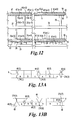
- FIG. 12 Schematic of machine with spaced cooling cuffs.
- FIG. 13A Cross section of S-ribbons showing possible locations for cooling channels with the channels completely enclosed in ribbons.
- FIG. 13B Cross section of S-ribbons showing cooling channels completely enclosed and channels impressed from ribbon surface.
- 45 MGOe magnet material is assumed, instead of 35 MGOe material in the modeling of FIGS. 6 and 7 .
- the power densities of available commercial electric motors and generators tend to be limited through cooling.
- 35 MGOe magnet material is used because it can tolerate higher temperatures before losing magnetization than 45 MGOe material.
- MP-T II machines are unlikely to be limited by cooling. Therefore use of 45 MGOe material is appropriate, especially since its price is much the same as that of 35 MGOe material.
- the optional twist in the individual S-ribbons is meant to prevent the current from crowding towards areas of low flux density, B. For this purpose one full twist per turn will be enough and more twists may be used for other reasons, e.g. greater conductor density or greater stiffness.
- triple S-ribbons are joined at insulating boundaries 174 ( n ).
- the folds illustrated in FIG. 8C need not be sharp. In fact, it will be difficult if not impossible to make sharp folds of twisted Litz wire cables without introducing cracks or at the least impairing their electrical conductivity.
- the “wrapping” of FIG. 8D avoids this problem. Both methods are possible because the indicated method of making and assembling current tubes from axially extended segments does not put significant constraints on current tube rim thickness, i.e. outside of the gap between magnet tubes 5 and 6 , i.e. either side of lines XX in FIG. 8 .
- the folds of FIG. 8C may be made by bending about cylindrical temporary inserts.
- FIG. 8C in making 180° turns by means of folding there is a choice whether successive folds are made into or out of the plane of the drawing.
- the version of FIG. 8C is the simplest.
- the width of rims due to wrapping will probably be of similar or lesser width.
- cooling cuffs namely fluid cooling tubing that encircle one or both current tube rims from the outside and/or the inside and are in close thermal contact with them
- cooling channels embedded into current tube walls
- FIG. 9 shows the basic machine morphology, including provision for two cooling methods.
- the first, simplest, are “cooling cuffs” ( 47 ) that surround one or both rims ( 3 ) or are incorporated into the hollows of 180° “wraps” as in FIG. 8D .
- the bonding area between the triple S-ribbons in the rim and the cuff(s), as well as the heat conductivity between S-ribbons and cuff(s) should be optimized.
- the triangular notches between neighboring rim units i.e. at the horizontal edges of FIG. 8A
- the thickness differences at the folds should preferably be filled-in with some heat conducting material.
- the rim(s) will need first to be covered with an insulating coating
- the space inside the “wraps,” could readily accommodate a cooling tube (labeled 40 in FIG. 8D ) that serves as a “cuff.”
- a cooling tube (labeled 40 in FIG. 8D ) that serves as a “cuff.”
- Such a tube might be bonded to the triple S-ribbons by means of a thin layer of insulating adhesive.
- cuffs may also be installed at the inside cylindrical surface. And both types of cuffs may be installed at both tube ends, as may be needed at any but very squat machines, i.e. at quite short current tube lengths, L.
- a numerical example of potential technological application of eq. 6Q is that of pancake-shaped in-wheel motors for hybrid cars or other wheeled or tracked vehicles.
- Cryogenic cooling can significantly extend the length limits of machines that may be cooled by cuffs because the electrical resistivity of metals, ⁇ , is roughly proportional to the absolute temperature, ⁇ , while their heat conductivity, ⁇ , is almost temperature independent.
- W M ( ⁇ C 3 ⁇ 4 ⁇ Dw C /t C ) ⁇ c (10Qa) which relationship determines the required value of ⁇ C w C ⁇ c /t C .
- the needed cuff width would be quadrupled, i.e. to about 3 cm, but only by half as much if a cuff is added also on the inside surface of the rim.
- MP-T II machines will preferably employ “flat” magnets of Case 3A as indicated in FIG. 7 .
- flat magnet arrays have the additional advantage that they will permit reducing the gaps between rotor and magnets, as indicated in FIG. 11 . While thereby the potential cooling channels that existed with Halbach arrangements are closed, the wall width of the current tube may be increased by about one quarter, and the small gaps that are formed between flat magnets and cylindrical current tube surfaces will trap and evenly distribute lubricant. Further, for effective cooling, channels 40 in the current tube wall may be used, as indicated in FIGS. 11 , 13 A and 13 B.
- FIG. 11 in regard to size and arrangement of cooling channels 40 , relative size of current tube wall width, and magnet dimensions, are widely adjustable, as further elaborated in FIGS. 13A and 13B .
- FIG. 9 similarly adjustable are the specifics of FIG. 9 .
- axle ( 10 ) e.g. by part 29 as in FIG. 9 .
- it may be magnet tube 6 rather than 5 that is rigidly fastened to axle 10 , or indeed the machine axis may be held stably in relation to the surroundings by any other suitable means.
- outer magnet tube 6 could be supported by a base plate fitted with bearings that keep the magnet tube axis in fixed position and that permit magnet tube 6 to freely rotate as indicated by part 28 in FIG. 1B and FIG. 12 .
- axle 10 the position of current tube 2 will be fixed in the gap between the two magnet tubes that rotate together on account of the mutual magnet attraction among the magnet pairs in them, while current tube 2 is prevented from rotating at a minimum by cables to power source and cooling connections.
- supports 29 and 181 are indicated by way of example, only, and may or may not even exist.
- cooling channels 40 and inflow and outflow tubes ( 41 and 42 ) will be made through the current tube wall where it will be permitted to extend slightly beyond the magnet tubes and before meeting the rim.
- FIGS. 13A and 13B Different morphologies for incorporating cooling channels into or between triple S-ribbons are indicated in FIGS. 13A and 13B .
- One of these is making matched indents near the centerline of individual S-cables that on fitting the S-cables together provide cooling channels.
- Those indents will not serve a useful purpose in the rims ( 3 ) outside of the current tube body, which comprise the 180° turns of the triple S-ribbons.
- those indentations will have to be shaped over closely the right lengths of S-ribbons, and either be omitted or closed off from fluid flow beyond lines XX XX in FIG. 8 .
- channels 40 near the current tube body limits (at lines X X) will need to be made to and from inlet and outlet tubes, 41 and 42 , and these must be leak-proof.
- N Z ⁇ D/L m/ , equations 4
- Multiphase Power Other than Three-Phase (n 3) and Optimized Magnet Arrangements
- MP-machines, motors as well as generators, and in particular MP-T II machines may be advantageously fitted with “flat” magnets sliding against boundary-lubricated current tubes with clearances of about 0.0006D against the magnets on the outer as well as the inner magnet tube, where D is the current tube diameter. Those clearances are needed to accommodate differential thermal expansion of the current tube versus the magnet tubes, assuming maximum temperature variations of 110° C.
- cooling channels ( 40 ) in the current tube wall and flowing cooling fluid through these preferably from an inflow feeding tube that encircles the current tube wall and exiting through a similar outflow draining tube at the other end of the current tube wall.
- the loss plays a central role in that it is proportional to the current density, j (see eq. 12) and so are the torque, the machine power and the power density (see eqs. 7, 8 and 20). Therefore if loss is set at some predetermined level, the typical effect is to thereby indirectly set the level of cost and power density, especially at low rotation rates, unless the current density is determined independently.
- Cooling channels occupy a fraction of the current-carrying, torque-producing area A Z .
- K the parameter K to permit adjustments of machine voltage
- the voltage may be increased by lowering K, since this raises the machine dimensions even while at set machine dimensions, V M is inversely proportional to K.
- reduction of K will increase construction cost of the machine.
- careful modeling is advisable before deciding on any particular design.
- specific materials cost is remarkable low and power density is high, in spite of the strongly elongated design of the present example.
- MP-T machines require electronic controls and will only coincidentally operate on 60 Hz current, it seems unlikely that large numbers of small MP-T machines will ever be used casually for mundane tasks, e.g. for operating car widows or powering vacuum cleaners and sewing machines. Even so, on account of their achievable high power densities, compact MP-T II machines, whether motors and/or generators, may have a future in high-tech applications, e.g. for drones, unmanned underwater vehicles or generators in space.
- D may be as small as, say, 10 cm or less and the rotation rate could be at least as high as 15,000 rpm. According to eq.
- FIG. 1A PRIOR ART shows a schematic cross section of an MP machine wherein current tube 2 rotates with the machine axle 10 , while the outer ( 6 ) and inner magnet tube ( 5 ) are stationary.
- a machine with current-channeling current tube in the motor mode is assumed that is powered by a DC power supply.
- An MP-A or MP-T motor would comprise a current tube fitted with one or more S-ribbons and would be powered with AC or three-phase
- FIG. 1B PRIOR ART: As FIG. 1A but for the case of an MP-A or MP-T machine, wherein magnet tubes 5 and 6 rotate with axle 10 while current tube 2 remains stationary on account of its mechanical anchoring to the base plate 19 via part 183 .
- FIG. 2A PRIOR ART is a perspective view with partially cut-out outer magnet tube 6 of a machine with the basic construction of FIG. 1A , but for the case of an insulating current tube 2 with embedded serpentine-shaped conductor (S-ribbon).
- FIG. 2B PRIOR ART: As FIG. 2A but for the geometry of FIG. 1B .
- the electrical connection to the outside i.e. power supply or consumer 171
- the machine is shortened, its power density increased and cost reduced.
- This design also makes multiple S-ribbons in one current tube possible which permits simultaneous use of different machine functions and power sources.
- FIG. 3A PRIOR ART is a plan view of S-ribbons in the current tube of an MP-T machine; In this view, magnets are located between lines XX and XX, namely above and below the plane of the drawing.
- FIG. 3B PRIOR ART reveals a cross sectional view of S-ribbons in the current tube body of an MP-T machine before compaction.
- FIG. 3C PRIOR ART shows a cross sectional view of S-ribbons in the current tube body of an MP-T machine after compaction.
- FIG. 4 PRIOR ART shows a selection of possible different magnet arrangements in any MP machine, including MP-A and MP-T machines in accordance with the present invention
- FIG. 5 Basic geometry used in finite element analysis of magnetic flux distributions for various cases by Eric Maslen of UVA.
- the critical dimensions for MP-T II machines are the magnet width L m/ that in these arrangements is identical to the periodicity distance 2L m , the magnet thickness H m , the thickness of the flux return material L b , and the gap width between opposing magnets L g that herein is assumed to be identical with the thickness of the current tube wall.
- FIG. 6 illustrates the morphology of magnets and field lines (in the geometry of FIG. 5 , top) and magnetic flux density at mid-line of current tube 2 (bottom) for Case 1A according to Eric Maslen, UVA, September 2005.
- FIG. 7 shows the morphology of magnets and field lines (in the geometry of FIG. 5 , top) and magnetic flux density at mid-line of current tube 2 (bottom) for Case 3A.
- the average magnetic flux density is expected to be 0.58 tesla instead of 0.51 tesla.
- this Case 3A appears to be the most favorable but logically cannot be the optimum.
- FIGS. 8A and 8B are the equivalent of FIG. 3 , clarifying current tube 2 construction of MP-T II machines from triple S-ribbons ( 173 ) comprising three parallel current paths for phases (a), (b) and (c), preferably made of mildly twisted compacted Litz wire cables.
- FIG. 8A is a plan view of the current tube wall between inner and outer magnet tubes ( 5 and 6 ), that terminate at lines XX . . . XX. The current tube wall extends beyond lines XX into rims where 180° turns ribbons 173 are located,—here shown made by folding.
- FIG. 8B shows a partial cross section through current tube 2 wall and magnet tubes 5 and 6 .
- the alternating direction of current flow in tandem with changing polarity of the magnets is indicated by circles with central dots or crosses, respectively.
- near maximum current flows in two phases (here (a) and (b)) while the third phase (here c) has minimal current because it straddles the borders between adjacent magnets where the flux density B changes direction.
- FIG. 8C shows the construction of 180° turn of triple S-ribbon 173 via three folds as labeled.
- FIG. 8D shows the construction of 180° turn of triple S-ribbon 173 via a mildly spiraling “wrap” about a slim rod or tube that may at the same time (as in this figure) serve as a “cuff” cooling channel ( 40 ).
- FIG. 9 illustrates the lengthwise cut through a brushless MP machine with stationary current tube, including provision for two possible alternative cooling arrangements. These are, (1) cooling by means of a “cuff” ( 47 ) that encircles at least one rim, is in good thermal contact with it (in this case rim 3 ( 2 )), and through which a coolant is passed.
- a “cuff” 47
- this method may be extended to much greater lengths; in the extreme case, i.e. liquid helium cooling, to L ⁇ 10 ft.
- a preferred cooling method uses cooling channels ( 40 ) within the current tube wall ( 2 ) and supplied with coolant via inflow and outflow tubes ( 41 and 42 ). Without loss of previously estimated performance, cooling channels 40 may occupy up to about 25% of the current tube wall. Channels 40 may be preferably connected to tubes 41 and 42 by passing through current tube wall 2 just outside of the zones, i.e. outside of the magnet tubes and before the joints between current tube wall and rims 3 ( 1 ) or 3 ( 2 ). This is at or close to the positions of optional magnetic shields ( 90 ), if used. Magnetic shields of annular shape are made of soft iron and cover the ends of the magnet tubes, thereby screening at least partly stray magnetic end-fields extending outside of the magnet tubes.
- FIG. 10 is a graph model for the derivation of eqs. 1Q to 4Q.
- FIG. 11 is the cross section through an MP-T machine with flat magnets in the outer ( 6 ) and inner ( 5 ) magnet tube, and with cooling channels ( 40 ) in the current tube wall ( 2 ).
- liquid or gaseous coolant e.g. air, or water, or an organic liquid, pre-cooled or not as may be desired, is passed through cooling channels ( 40 ) between feeding and draining tubes 41 and 42 indicated in FIG. 9 .
- magnets are flat i.e. of uniform thickness, as indicated in this figure.
- the arrangement of cooling channels 40 as well as their shapes and sizes is optional.
- FIG. 12 shows the lengthwise cross section of part of an MP-T II machine with cooling through periodic cooling “cuffs” ( 47 ) that encircle the current tube ( 2 ).
- the current tube rim ( 3 ) comprises 180° turns of the S-ribbons, in this case of the mildly spiraling “wrap” type shown in FIG. 8D .
- those wrap type 180° turns encircle a cooling channel ( 40 ) that here functions in the role of a cooling cuff.
- the figure shows two mildly different constructions, namely on the right with the inner magnet tube ( 5 ) continuous while the outer magnet tube ( 6 ) is periodically interrupted by cooling cuffs. According to the derivation of eqs.
- the various sections of the outer magnet tube labeled 6 ( n ), 6 ( n ⁇ 1) etc., will rotate together with the inner magnet tube on account of the mutual magnetic attraction between the magnet pole pairs. Supports 28 with bearings 35 on base plate 19 shown in the figure, are expected to directly help smooth the rotation of the outer magnet tube sections ( 6 n ), and indirectly the smooth running of the whole machine.
- the potential benefit of mechanically separating inner magnet tube 5 into sections as at left could be savings in magnet material.
- the magnets are preferably omitted at the gaps of outer tube 6 in order to save cost, since, locally, without the opposing outer magnets, the inner magnets cannot fully maintain the magnetic flux density in the gaps where the cooling cuffs are applied.
- the decision on whether or not to segment also the inner magnet tube will then have to be based on other than magnet cost considerations, e.g. mechanical stability, manufacturing cost, etc.
- FIGS. 13A and 13B show examples of possible arrangements of cooling channels ( 40 ) in the wall of a current tube ( 2 ) whose midline is indicated with label 4 .
- FIG. 13A illustrates cases in which the cooling channels are wholly confined in the current tube wall
- FIG. 13B shows wholly confined cooling channels ( 40 ( 6 ) and 40 ( 7 )) as well as cooling channels bordering the surface of 2 and thus adjoining the sliding interfaces 37 and/or 38 , namely 40 ( 5 ), 40 ( 8 ) and 40 ( 9 ).
- the considerable advantages of cooling channels bordering the sliding interfaces include (i) ease of manufacture (e.g.
- cooling channel wall ( 48 ) that will be electrically insulating, leak-proof, and durable during long-time sliding against either of the magnet tubes and the magnets mounted on them.
- the above figure aims to show that optionally, different types of channels may be simultaneously used in the same current tube, that the channel cross section may be circular as in the top part of this figure), elliptical 40 ( 6 ) 40 ( 7 ) and 40 ( 9 ) or polygonal 40 ( 5 ) and 40 ( 8 ), that they may or may symmetrically oriented to the current tube mid-plane 40 ( 6 ) and 40 ( 7 ), that they may straddle the boundaries between adjacent current paths of phases 40 ( 6 ) and 40 ( 7 ) and/or of the boundaries between adjacent triple S-ribbons ( 174 ) ( 40 ( 1 ), 40 ( 2 ), 40 ( 4 ), 40 ( 5 ), 40 ( 8 ) and 40 ( 9 )), in addition to any other possible permutations such as placing them asymmetrically relative to mid-plane 4 and current tube surfaces.
Landscapes
- Engineering & Computer Science (AREA)
- Power Engineering (AREA)
- Motor Or Generator Cooling System (AREA)
- Dynamo-Electric Clutches, Dynamo-Electric Brakes (AREA)
- Permanent Field Magnets Of Synchronous Machinery (AREA)
Abstract
Description
-
- We may repeat the previous description in Patent Application PCT/US05/30186 filed 24 Aug. 2005) as follows, including re-numberings as appropriate:
-
FIGS. 1 and 2 clarify two possible basic geometries of simple cylindrical MP machines, namely (i) with rotating current tube (2) in the gap between stationary inner (5) and outer (6) magnet tubes (FIGS. 1A and 2A ), and (ii) of stationary current tube (2) and rotating inner (5) and outer (6) magnet tubes (FIGS. 1B and 2B ). In the first case, i.e. inFIG. 1A ,current tube 2 is rigidly fastened to machineaxle 10, namely viadrivers 61, so that in the motor mode it drives the axle rotation, and in the generator mode is driven by the axle. Meanwhilemagnet tubes low friction bearings 35 but are mechanically anchored to the surroundings, e.g. themachine base plate 19 via supports 25 inFIG. 1A . In the second case,FIG. 1B , the roles are reversed. Nowmagnet tubes axle 10 viaparts axle 10 or be driven by it, in the motor and generator modes, respectively. Nowcurrent tube 2 is centered on, but does not rotate with,axle 10, namely viaparts 181 andlow friction bearings 35. As indicated by the different power sources, i.e. DC inFIG. 1A and AC inFIGS. 1B and 2 , current flows through the current tube, as is the case for all MP-machines, and therefore, in the cases ofFIGS. 1A and 2A , has to be supplied to movingcurrent tube 2 by brushes 27(n). However, to a stationary current tube, as inFIG. 2B , current may be supplied by means of stationary terminals in the motor mode, or power may be extracted from MP-T generators through the same stationary terminals. - It may be noted that a central axle may not be needed and that anchoring to any other part of stationary surroundings of machines may be used to center rotating components, albeit probably not as satisfactorily. Anyway, from the mechanical viewpoint, either the current tube or the magnet tubes may rotate with or without a machine axle. The following are some pertinent general considerations.
- Simple MP machines have rotationally symmetric current tubes as well as rotationally symmetric magnet tubes. The asymmetry imposed by stationary terminals to outside power supplies and/or customers is readily accommodated by rotating current tubes, the currents in which are fed to and/or extracted from the current tube by means of electrical brushes. Also MP-Plus machines have rotationally symmetric current tubes but they do have asymmetric magnet tubes. These are pairs of N/S S/N poles side by side, relative to which the power terminals have to remain stationary. This situation, again, calls for rotating current tubes connected to the outside by means of sliding brushes. However, MP-A and MP-T machines have rotationally symmetrical magnet tubes but current tubes with built-in asymmetry, namely S-ribbons or S-ribbon sections with ends projecting beyond the zones. This situation permits both, rotating current tubes and rotating magnet tubes, as shown in
FIGS. 2A and 2B . However, while the interconnections between rotating current tubes and stationary power supplies and/or customers again require sliding electrical brushes, as inFIG. 2A , stationary slip rings as inFIG. 2B can be supplied by means of stationary terminals, thereby eliminating slip rings and brushes. - In summary, the fundamental difference between MP and MP-Plus machines on the one hand, and MP-A and MP-T machines on the other hand, lies in the morphology of the current tube (2). The current tubes of MP and MP-Plus machines are rotationally symmetrical, as already indicated, whereas the current tubes of MP-A machines comprise at least one conductive S-
ribbon 172 in an electrically insulating matrix (seeFIG. 2 ), and the current tubes of MP-T machines contain three similar, regularly spaced S-ribbons in any one series of consecutive zones (seeFIG. 3 ) each with two terminals for feeding current in and out.
-
- As already indicated, the arrangement of the sources of magnetization in the magnet tubes, that generate zones in the [current tube] is optional, as indeed is their nature. Above, the discussion has centered on permanent magnets as the sources of magnetization although it could also be electromagnets, and among these Hallbach arrangements as in FIG. [4A] have been the focus of attention. However, a wide range of alternative arrangements is possible of which examples are given in FIGS. [4]B, [4]C and [4]D, wherein 130, with a dotted pattern, is a non-magnetic material such as a plastic, a rosin or a ceramic, 131, indicated by short wavy lines, is a flux return material, e.g. a magnetically soft iron alloy such as FeSi. Finally, 132, characterized by longer lines, is a permanent magnet material.
dQ/dt=j 2 A i ρdx (1Q)
which shall be removed by heat conduction to a heat sink at x=L (not shown in
dQ/dt=λA i dθ/L. (2Q)
Thus from equating eqs. 1Q and 2Q, we obtain dθ/dx=j2ρ(L−x)/λ or for the temperature difference between x=0 and x=L
With an upper limit on the temperature difference between the two ends of, say, Δθmax (as in practice will always be present), the maximum allowable current density then becomes
j max=(2λΔθmax /ρL 2)1/2. (4Qa)
(λ/ρ)Litz=1.6×1010 [w/° C.Ωm2]=1.6×10¹⁰[A2/° C.m2] (5Qa)
and from eq. 4Qa
j max,Litz=(2×1.6×1010Δθmax /L 2)1/2=1.79×105(Δθmax /L 2)1/2. (6Q)
Δθmax=(2.25×10⁷/1.79×105)20.0552[mks]=48° C. (7Q)
This value of Δθmax=48° C. would be acceptable, as it would not degrade the magnets (at about 150° C.), even with a cuff at only one end and the heat sink end at an ambient temperature as high as, say, 70° C., whereas cuffs at both ends would halve L and thus cut Δθmax to ¼ 48° C.=12° C.
L max=(2λΔθmax/τ)1/2 /j (4Qb)
which for a desirable current density of j=1×10⁷ A/m2 and with otherwise the same values yields
L max=(2λΔθmax/ρ)1/2 /j=0.0179√Δθmax[mks]. (4Qc)
Since without cryogenic cooling, numerically Δθmax can hardly exceed 64° C. or √Δθmax≦˜8(° C.1/2) this means that for machines that are not cooled cryogenically, the longest distance to the nearest cuff may not exceed ˜8×0.0179=0.14 m, for a maximum zone length of Lmax≅1 ft of a machine cooled by cuffs at both ends.
(λ/ρ)Litz=1.6×1010(300/θ)[A2/° Cm2]=4.8×10¹²[A2/° Cm2] (5Qb)
and for the maximum distance to a cuff with otherwise the identical parameters,
L max,θ =L max,amb(300/θ)1/2. (4Qd)
dQ/dt=(λC A C /t C)Δθc (8Q)
For a cuff of axial length wc encircling the rim of a current tube of diameter D, it will be
A C =f c πDw C≅¾πDw C (9Q)
where the factor of fc is the fraction of rim or current tube circumference that is in good thermal contact with the cuff(s). Provisionally this is assumed to be fc≅¾ in line with
which relationship determines the required value of λCwCΔθc/tC. Now, numerically (consistently in mks units) the heat conductivity of a well chosen adhesive and material for the thin barrier between the cuff and the rim, will presumably be no less than λC=1.7 w/° Cm as for ice and concrete; and the barrier thickness may be made as small as tC≅3×10⁻⁵ m, i.e. the thickness of a strong kitchen trash bag. With these values, and assuming a permissible value of Δθc=50° C., one obtains from eq. 10Qa
w C=0.093×5.6×104/{0.32×6.7×106 D)=0.76 cm. (10Qc)
It follows that as far as transfer of the heat from the outermost rim layer into the cooling fluid in the cuff is concerned, a very narrow cuff will suffice. However, the example pertained to an NT=4 layered machine and one must additionally consider the heat flow resistance of the three adhesive layers in the rim. If these should offer the same heat flow resistance as the surface bond between cuff and current tube rim, the needed cuff width would be quadrupled, i.e. to about 3 cm, but only by half as much if a cuff is added also on the inside surface of the rim.
Assume that this waste heat shall be removed by cooling water flowing through cooling channels of combined area ¼πDT at speed vc having specific heat c=1 cal/cc° C.=4.2 ws/cc° C. and being heated through an inflow/outflow temperature difference of ΔθC, i.e.
dQ C /dt=¼πDT×v C ×c×Δθ C =d
It follows that
v C ×c×Δθ C=2Lρj 2 (13Q)
or numerically, with c=4.2×10⁶ [ws/° Cm3] and ρ≅2.0×10⁻⁸ Ωm for bundled, compacted Litz wires as before,
v C×ΔθC=2Lρj 2 /c=9.5×10−15 Lj 2[mks]. (14Q)
v C,5m,50o=9.5×10⁻¹⁶ j 2. (15Qa)
Moreover, if this should be limited to the conservative value of vC≦1 m/sec≅2.2 mph, the largest permissible current density becomes
j max,5m,50o=(1/9.5×10−16)1/2[mks]=3.2×107 A/m2=3200 A/cm2. (15Qb)
This means that cooling via water flow through
(Lj 2)max,50olm/s≦5.2×1015 [A2/m3] (15Qc)
i.e. at L=1 m to j=7200 A/cm2. These greatly exaggerated figures show that cooling channels occupying 10% or less of the current tube wall width will be adequate under virtually all circumstances.
Summary
- (i) “flat” magnets in lieu of Halbach arrangements, thereby increasing the power density;
- (ii) “triple S-ribbons” with 180° turns or either of two types in “rims” that greatly simplify machine construction;
- (iii) improved cooling and lubrication by two alternative methods.
A Z=(⅓)L m/ T=(⅓)K 2 L m/o T o cross section of current flow per phase,
B=Effective magnetic flux normal to current,
C M=Materials Cost of machine=$40×m m+$10×(m M −m m),
D=Diameter at current path midline,
d≅8000 kg/m3=Mechanical density of machine materials (assumed the same for all),
F 1=Lorentz force per turn,
H m =KH mo=Thickness of permanent magnets,
I=Current through individual turn=Ja Z,
i M=2i=Machine current (assuming two phases pass through B in a zone at any one time),
j=Current density,
K=Scaling factor for magnet assembly dimensions,
L=Length of current tube,
L b =KL bo=Radial thickness of flux return material,
L m/ =KL m/o=Zone width, i.e. width of permanent magnets in circumferential direction,
M M =W M/2πν=Machine torque,
N T=Number of layers,
N U=Number of essentially independent units into which machine is divided,
N Z =πD/L m/=Number of zones,
R 1=Ohmic resistance per zone,
v r =πDν=(π/60)Dω rpm=Relative velocity between current and permanent magnets,
V M =N Z V 1=Machine voltage,
V 1=Induced voltage per zone,
V Ω1=Ohmic voltage in current path per zone,
t.□=ω rpm/60=Rotation rate in Hertz,
ρ≅2×10⁻⁸ Ωm=Electrical resistivity in current path,
ωrpm=60ν=Rotation rate in rpm.
Key Equations for MP-T II, Three-Phase Machines
(compare Table, [mks] units throughout with watt, Amp and Volt; too many significant figures are retained to avoid accumulation of rounding errors)
Construction Parameters
(NT=Nu=1; with Case 3A, i.e. Hm=KHmo=K 0.0125 m, Lm/=6Hm, Lb=Hm, T=2Hm, B=0.58t, only two of three phases flow in field B at any one moment; d=8000 kg/m3, ρ=2×10⁻⁸ Ωm)
Current Path Area per Phase: A Z=(⅓)TL m/=4H m 2=4K 2 H mo=6.25×10⁻⁴ K 2[m2] (1)
Current per phase: I
Current Density: j=i/A Z =i/6.25×10−6 K 2=1600K 2 I[A/m2] (2)
Effective Machine Current or of Independent Section: i M=2i=2Ja Z=1.25×10⁻³ K 2 j (3)
(assuming that two of three phases flow in peak magnetic flux density, B, at any one moment)
Number of zones: N Z =πD/L m/ =πD/6H m =πD/6KH mo=41.9 D/K [mks] (4)
Lorentz Force per Zone: F 1 =i M BL=1.25×10⁻³ K 2 BLj (5)
Total Lorentz Force F=N Z F 1=3.04×10⁻² KDLj (6)
Torque: M M=(D/2)N Z F 1=0.0152KD 2 Lj (7)
Machine Power: W M=(2πωrpm/60)M M=1.59×10⁻³ KD 2 Ljω rpm (8)
Voltage per Zone V 1 =v r BL=(π/60)Dω rpm BL=3.04×10⁻² N T Dω rpm L (9)
Machine Voltage: V M =N Z V 1=1.27D 2 Lω rpm /K (10)
Ohmic Voltage Loss per Zone*: V 1Ω =ρLj (11)
Relative Ohmic Loss:
Ohmic Machine Resistance: R M =N Z ρL/A Z=1.34×10⁻³ DL/K 3 (13)
Mass of Magnet Material: m m=2πdDLKH mo=628KDL [kg] (14)
Flux Return Material Mass: m b=2πdDLKL bo=628KDL=m m[kg] (15)
Current Path Mass: m Cu≅2πdDLKT o≅628KDL=m m[kg] (16)
Cost of Magnet Material: C m=$40×m m=$25,100KDL (17)
Machine Mass: m M=1.3(m m +m b +m Cu)=1.3×3m m=3.9m m=2450KDL [kg] (18)
Machine Material Cost: C M=$40×m m+$10×(m M −m)=$10×(4+2.9)m m=1.77C m=$44,400KDL (19)
Power Density: W M /m M=6.45×10⁻⁷ Djω rpm or m M /W M=1.55×10⁶ /Djω rpm (20)
Cost per Unit of Power: C M /W M=$2.79×10⁷ /Djω rpm (21)
| TABLE I |
| Forecast Performance of MP-T II Machines with NT = NU = 1, all in [mks] |
| (Summary of eqs. 1 to 21 above) |
| MP-T II (Case 3A, B = 0.58 tesla) | MP-T (Case 1A, B = 0.56 tesla) |
| Hmo = Lbo = 1.25 cm, Lm/o = 7.5 cm To = 2.5 cm | Hmo = Lbo = 1.25 cm, Lm/o = 2.5 cm To = 2.5 cm |
| AZ = (⅓)K2Lm/oTo = 6.25 × 10⁻⁴K2 [m2] | AZ = (⅓)K2Lm/oTo = 2.08 × 10⁻⁴K2[m2] |
| vr = πDν = (π/60)Dωrpm = 0.0524 Dωrpm | vr = πDν = (π/60)Dωrpm [m/s] |
| V1 = vr BL = (π/60)BDLωrpm = | V1 = vr BL = (π/60)BDLωrpm = |
| 0.0304DLωrpm [V] | 0.0293DLωrpm [V] |
| NZ = πD/Lml = 41.9.1D/K | NZ = πD/Lm/ = 126 D/K |
| VM = NZV1 = (41.9D/K)V1 = | VM = NZ V1 = (126 DK) V1 = |
| 1.27 D2 Lωrpm/K [mks] | 3.69 D2Lωrpm /K [mks] |
| i1 = j AZ = 6.25 × 10⁻⁴K2 j [mks] | i1 = j AZ = 2.08 × 10⁻⁴K2 j [mks] |
| iM = 2 i1 | iM = 2 i1 |
| R1 = ρL/AZ = 3.2 × 10⁻⁵ L/K2 [mks] | R1 = ρL/AZ = 9.61 × 10⁻⁵L/K2 [mks] |
| ρ = 2 × 10⁻⁸Ωm | ρ = 2 × 10⁻⁸Ωm |
| RM = NZ R1 = 1.34 × 10⁻³DL/K3 [mks] | RM = NZR1 = 1.21 × 10⁻² DL/K3 [mks] |
| V1Ω = i1 R1 = ρL j = 2 × 10⁻⁸Lj | V1Ω = i1R1 = ρL j = 2 × 10⁻⁸Lj |
| |
|
| MM = (D/2)NZ i1LB = 0.0152KD2 L j | MM = 2 (D/2) NZi1LB = 0.0146KD2 L j |
| (assume 2 of 3 phases work together, which | (assume 2 of 3 phases work together, but |
| is probably sound) | this is probably an over-estimate) |
| WM = MM2πωrpm/60 = 0.00159KD2Ljωrpm | WM = MMπωrpm/30 = 0.00153KD2Ljωrpm |
| mm = d2πDLKHmo ≅ 628 KDL [mks] | mm = d2πDLKHmo ≅ 628 KDL [mks] |
| d = 8000 kg/m3 | |
| mM ≅ 3.9 mm ≅ 2450 KDL [mks] | mM ≅ 2.6dπDL(KHmo + KLbo + KTo/2) = |
| 1.3Tmm[1 + (Lbo + To/2)/Hmo] ≅ 3.9mm ≅2450KDL | |
| WM/mm = 2.43 × 10⁻⁶Djωrpm [mks] | WM/mm = 1.83 × 10⁻⁶Djωrpm |
| WM/mM = 6.47 × 10⁻⁷Djωrpm [mks] | WM/mM ≅ 4.69 × 10⁻⁷Dj ωrpm [mks] |
| Cm ≅ $40 × mm = $25,100 KDL [$mks] | Cm ≅ $40 × mm = $25,100 KDL [$mks] |
| CM = 1.77Cm = $44,400 KDL [$mks] | CM ≅ 1.72 Cm ≅ $43,340 KDL [$mks] |
| CM/WM ≅ $2.79 × 10⁷/Dj ωrpm [$mks] | CM/WM ≅ $3.77 × 10⁷/Djωrpm [$mks] |
M M=0.0152KD 2 Lj=3850 (7a)
for
KD 2 Lj=2.52×10⁵ [mks]. (23a1)
The first decision will be the choice of K, which will be made as small as possible in order to lighten the machine and save cost of permanent magnet material but without unduly complicating practicalities of machine construction. Provisionally we may choose K=0.25 to let the magnets be Hm=K 1.25 cm=0.31 cm thick and the zones be 6Hm=1.88 cm wide in circumferential direction. With this choice of K=0.25 we obtain
D 2 Lj=2.52×10⁵ /K=1.01×106 [mks]. (24a1)
The next choice then is of the current density j. One will wish to make this as large as possible in order to obtain a small value of D2L and thus low magnet and machine weight, but one is constrained by the fact that the loss,
Choosing
for
j=1.21×10⁷ D. (27a)
j=6.67×10⁶ [A/m2]=667 A/cm2 (28a1)
and from eq. (24a1)
L=1.01×10⁶ /D 2 j=0.50m. (29a)
m m≅628KDL=43.2 kg (14a1)
costing Cm≅$1,730 and, following eqs. 18 and 19, the machine mass will be
m M=2450KDL=168 kg=370 lbs (18a1)
costing
C M=$44,400KDL=$3050 (19a1)
for a weight power density of
m M /W M=1.55×10⁶ /Djω rpm=3.5 lb/hp (20a1)
and specific materials cost
C M /W M=$30.5/hp. (21a1)
V M=1.27D 2 Lω rpm /K≅154 V (10a1)
for a machine current of
i M ≅W M /V M=490 A. (30a1)
Same Machine but Equiaxed, i.e. L=D, with “Floating Loss” and K=0.25
D 2 L=2.52×10⁵ /Kj max=0.084 [m3 ]=D 3=(0.438 m)3. (23a2)
This results in a loss of
and magnet mass
m m≅628KDL=30.1 kg (14a2)
costing Cm≅$1,205. Then, following eqs. 18 and 19, the machine mass will be
m M=2450KDL=118 kg=260 lbs (18a2)
at cost
C M=$44,400KDL=$2,130 (19a2)
for a weight power density of
m M /W M=1.55×10⁶ /Djω rpm=2.4 lb/hp (20a2)
and specific materials cost
C M /W M=$21.3/hp. (21a2)
V Mcorr=(1.27D 2 Lω rpm /K)(1−
for a machine current of
i M ≅W M /V M=790 A. (30a2)
Same Machine with
D 2 Lj=3850/(0.0152K)=2.53×105 [mks]. (24a2)
Then with the same 4% loss, diameter of D=0.55 m and current density of 6.67×10⁶ A/m2, find
L=2.53×10⁵/(0.552×6.67×106 A)=0.125 m (24a3)
with the same magnet mass
m M=628KDL=43.2 kg (14a3)
but voltage V M=1.27D 2 Lω rpm /K≅9.6 V (10a3)
and current
i M ≅W M /V M=7810 A (30a3)
a patently absurd design. Thus, primarily, choice of K is a tool for achieving a desirable voltage.
Same Machine with K=0.25 and
j=1.21×10⁷ D=9.68×10⁶ A/m2 (28a4)
and from (24a1) with K=0.25, D=0.8 m and j=9.68×10⁶ A/m2 find
L=2.52×10⁵/(D 2 Kj)=0.163 [m] (24a4)
for
m m=628KDL=20.4 kg (14a4)
and
m M=2450KDL=79.9 kg=175 lbs (18a4)
for
m M /W M=1.75 hp/lb or W M /m M=0.94 Kw/kg. (20a4)
while
V M=1.27D 2 Lω rpm /K≅106 V
with
i M ≅W M /V M=708 A (30a4)
and
C M /W M=$2.79×10⁷ /Djω rpm=$14.4/hp. (21a4)
Thus a considerable cost decrease is bought at the expense of a remarkably squat machine (α=L/D=0.163/0.80=0.20) as well as a significantly lowered machine voltage.
Conclusions
M M=0.0152KD 2 Lj=3.62×10⁵ [mks] (7b)
i.e.
KD 2 Lj=2.38×10⁷ [mks]. (23b1)
With K=0.40 (based on the considerations above) we obtain
D 2 Lj=2.38×10⁷ /K=5.95×107 [mks]. (24b1)
for
j=7.28×10⁶ D (27b1)
and by inserting 27b into eq. (24b1) find
D 3 L7.28×106=5.95×10⁷ [mks], i.e. D 3 L=8.17 m4. (31b1)
D=1.69/α1/4[m] and L=α 3/41.69 [m]. (31b2)
Consequently, with K=0.4 obtain
m m=628KDL=251(1.69/α1/4)(α3/41.69)=α1/2718 kg. (14b1)
D=2.01m and L=1.00m (31b3)
for which equation (14b1) yields
m m=628KDL=628×Kα 1/21.692=508 kg (14b2)
at a cost of
C m=$20,300 (17b1)
while
m M=3.9m M=1980 kg=4360 lbs (18b1)
at cost
C M=1.77C m=$35,900 (19b1)
or C M /W M=$5.9/hp. (21b1)
The resulting power density is
m M /W M=0.71 lbs/hp or W M /m M=2.30 Kw/kg. (20b1)
Further, the voltage is found at
V M=1.27D 2 Lω rpm /K≅1,540 V (10b1)
with i M≅4550 Kw/1540 V=2950 A (30b1)
Same Machine but Equiaxed, i.e. L=D, with “Floating Loss” and K=0.4
Torque equation (7b) yields with j=jmax=1.2×10⁷ A/m2, K=0.25 and L=D
M M=0.0152KD 2 Lj=3.62×10⁵ [mks] (7b)
D 2 L=2.38×10⁷ /Kj max=4.96 [m3 ]=D 3=(1.70m)3 (23b2)
resulting in loss
and magnet mass
m m≅628KDL=726 kg (14b2)
costing Cm≅$29,000. Then, following eqs. 18 and 19, the machine mass will be
m M=2450KDL=2830 kg=6230 lbs (18b2)
at cost
C M=$44,400KDL=$51,300 (19b2)
for a weight power density of
m M /W M=1.55×10⁶ /Djω rpm=1.0 lb/hp (20a2)
and specific materials cost
C M /W M=$8.4/hp. (21a2)
V Mcorr=(1.27D 2 Lω rpm /K)(1−
for a machine current of
i M ≅W M /V M=2330 A. (30b2)
Conclusion
This example shows that there is an upper limit to
Same Machine with K=0.4,
D=L=1.69m (31b4)
for a magnet material mass
m M=628KDL=628×K×1.692=717 kg (14b3)
machine mass
m M=3.9m M=2800 kg=6155 lbs (18b1)
and power density
m M /W M=1.01 lbs/hp or W M /m M=1.62 Kw/kg. (21b1)
V M=1.27D 2 Lω rpm /K≅1,840 V (10b2)
with current
i M ≅W M /V M=2470 A. (30b2)
C M /W M=$50,760/6100 hp=$8.3/hp. (21b2)
Elongated Machine (α=3) for Podded Ship Drive with K=0.3 & Floating Loss
KD 2 Lj=3.62×10⁵ Nm/0.0152=2.38×107 [mks] (24b2)
obtain with K=0.32 (for a not too low voltage), with L=αD=3D and jmax=1.2×10⁷ A/m2,
D 2 L=αD 3=2.38×10⁷ /Kj max=6.19 [m3]=(α1/31.84 [m])3 (23b3)
i.e.
D=1.84/α2/3=0.88 m and L=1.84α1/3=2.65 m (31b4)
resulting in a loss of
With these values, i.e. K=0.32, D=0.88m and L=2.65m, the magnet mass becomes
m m=628KDL=469 kg (14b4)
at a cost of
C m=$18,750 (17b3)
while
m M=3.9m m=1,830 kg=4,020 lbs (18b3)
at cost
C M=1.77C m=$33,200 (19b3)
or
C M /W M=$5.4/hp. (21b3)
The resulting power density is
m M /W M=0.66 lbs/hp or W M /m M=2.50 Kw/kg (20b3)
and the voltage and current are
V M=1.27D 2 Lω rpm /K≅980 V (10b3)
i M ≅W M /V M=4550 A. (30b3)
| TABLE III |
| Summary of Numerical Examples |
| WM | ωrpm | K |
|
D | L | VM | im | mM | CM | mM/WM | CM/WM |
| 100 hp | 200 rpm | 0.25 | 4.0% | 0.55 m | 0.50 m | 154 V | 490 A | 168 kg | $3,050 | 3.5 lb/hp | $30.5/hp |
| ″ | ″ | 0.25 | 9.03% | 0.438 m | 0.438 m | 95 V | 790 A | 118 kg | $2,130 | 2.4 lb/hp | $21.3/hp |
| ″ | ″ | 1.0 | 4.0% | 0.55 m | 0.125 m | 9.6 V!! | 7810 A! | ||||
| ″ | ″ | 0.25 | 4.0% | 0.80 m | 0.163 m | 106 V | 708 A | 79.9 kg | $1,440 | 1.76 lb/hp | $14.4/hp |
| 6100 hp | 120 rpm | 0.40 | 4.0% | 2.01 m | 1.00 m | 1540 V | 2950 A | 1980 kg | $35,900 | 0.71 lb/hp | $5.9/hp |
| ″ | ″ | 0.40 | 3.9% | 1.70 m | 1.70 m | 1950 V | 2330 A | 2830 kg | $51,300 | 1.0 lb/hp | $8.4/hp |
| ″ | ″ | 0.40 | 4.0% | 1.69 m | 1.69 m | 1840 V | 2740 A | 2800 kg | $50,720 | 1.01 lb/hp | $8.3/hp |
| ″ | ″ | 0.32 | 7.5% | 0.88 m | 2.65 m | 980 V | 4550 A | 1830 kg | $33,200 | 0.66 lb/hp | $5.4/hp |
| TABLE II |
| Characteristics of Halbach and Flat Magnet Arrangements |
| 9 | 10 | 11 | ||||||||||||
| 2 | 3 | 4 | 5 | 6 | 6 | 8 | λn = | δn = | μn = | 12 | 13 | 14 | 15 | |
| 1 | Lm0n | Lg0x | T0x = | Hm0n | Lb0n | Bx | βn = | Lm0n/ | T0n/ | Hm0n/ | WMn/mmn | κμnVM | 3μn/8 = | (VMn/VMH)mn |
| X | [cm] | [cm] | [cm] | [cm] | [cm] | [tesla] | Bn/BH | Lm0H | T0H | Hm0H | α βn 2 δn/μn | α βn/λn | minκμn | αβn/minκμnλn |
| H | 2.15 | 1.55 | 2.85 | 0 | 0.80 | 1 | 1 | 1 | 1 | 1 | 1 | |||
| 1B | 2.0 | 2.5 | 1.88 | 0.75 | 1.25 | 0.38 | 0.475 | 0.93 | 1.21 | 0.263 | 1.04 | 0.511 | 0.099 | 5.18 |
| 2B | 2.0 | 2.5 | 1.88 | 1.00 | 1.25 | 0.43 | 0.544 | 0.93 | 1.21 | 0.351 | 1.02 | 0.585 | 0.132 | 4.43 |
| 3B | 2.0 | 2.5 | 1.88 | 1.25 | 1.25 | 0.46 | 0.575 | 0.93 | 1.21 | 0.439 | 0.911 | 0.618 | 0.165 | 3.75 |
| 4B | 2.0 | 2.5 | 1.88 | 1.75 | 1.25 | 0.51 | 0.636 | 0.93 | 1.21 | 0.614 | 0.797 | 0.684 | 0.230 | 2.97 |
| 1A | 2.5 | 2.5 | 1.88 | 1.25 | 1.25 | 0.56 | 0.700 | 1.16 | 1.21 | 0.439 | 0.945 | 0.603 | 0.165 | 3.65 |
| 2A | 5.0 | 2.5 | 1.88 | 1.25 | 1.25 | 0.63 | 0.788 | 2.33 | 1.21 | 0.439 | 1.71 | 0.338 | 0.165 | 2.05 |
| 3A | 7.5 | 2.5 | 1.88 | 1.25 | 1.25 | 0.66 | 0.825 | 3.49 | 1.21 | 0.439 | 2.27 | 0.236 | 0.165 | 1.43 |
| 4A | 2.5 | 2.5 | 1.88 | 2.50 | 2.50 | 0.62 | 0.775 | 1.16 | 1.21 | 0.877 | 0.828 | 0.668 | 0.329 | 2.03 |
| 5A | 5.0 | 2.5 | 1.88 | 2.50 | 2.50 | 0.85 | 1.06 | 2.33 | 1.21 | 0.877 | 1.55 | 0.455 | 0.329 | 1.38 |
| 6A | 7.5 | 2.5 | 1.88 | 2.50 | 2.50 | 0.86 | 1.075 | 3.49 | 1.21 | 0.877 | 1.59 | 0.308 | 0.329 | 0.936 |
| 7A | 2.5 | 2.5 | 1.88 | 3.75 | 3.75 | 0.64 | 0.80 | 1.16 | 1.21 | 1.32 | 0.587 | 0.690 | 0.495 | 1.39 |
| 8A | 5.0 | 2.5 | 1.88 | 3.75 | 3.75 | 0.91 | 1.13 | 2.33 | 1.21 | 1.32 | 1.17 | 0.485 | 0.495 | 0.98 |
| 5B | 7.5 | 2.5 | 1.88 | 3.75 | 0.75 | 0.78 | 0.98 | 3.49 | 1.21 | 1.32 | 0.87 | 0.281 | 0.495 | 0.568 |
| 6B | 7.5 | 2.5 | 1.88 | 3.75 | 1.25 | 0.85 | 1.06 | 3.49 | 1.21 | 1.32 | 1.03 | 0.303 | 0.495 | 0.612 |
| 7B | 7.5 | 2.5 | 1.88 | 3.75 | 2.50 | 0.95 | 1.19 | 3.49 | 1.21 | 1.32 | 1.30 | 0.341 | 0.495 | 0.689 |
| 9A | 7.5 | 2.5 | 1.88 | 3.75 | 3.75 | 0.99 | 1.24 | 3.49 | 1.21 | 1.32 | 1.41 | 0.355 | 0.495 | 0.717 |
| Cases XA from E. Maslen report of Sep. 27, 2005, Cases XB from E. Maslen report of May 24, 2006 | ||||||||||||||
| X = Case; Lm = zone width; Hm = magnet tube wall width; T = current tube wall width = ¾ gap width, Lg Bn for 45MGOE | ||||||||||||||
| LABELS |
| 2 | current tube |
| 3 | “rim” of 180° turns of S-cables or triple S-ribbons |
| 4 | mid-line of current tube |
| 5 | inner magnet tube |
| 6 | outer magnet tube |
| 10 | axle |
| 19 | machine base plate |
| 23 | mechanical support for axle 10 on machine base plate 19 via low friction bearing 35 |
| 25 | rigid mechanical support of outer magnet tube 6 on base plate 19 to keep 6 centered on axle 10 |
| 26 | mechanical connection centering inner magnet tube 5 on axle 10 via low-friction bearing 35 |
| 27 | electrical brush, 27(1) and 27(2) sliding on slip rings 34(1) and 34(2), respectively |
| 28 | mechanical support of outer magnet tube 6 on base plate 19 via low-friction bearing 35 |
| 29 | rigid mechanical connection between inner magnet tube 5 and axle 10 so as to rotate together |
| 33 | brush holder |
| 34 | slip ring; inner slip ring 34(1), outer slip ring 34(2) |
| 35 | low-friction bearing |
| 37 | cylindrical gap/sliding interface between current tube 20 and inner magnet tube 5 |
| 38 | cylindrical gap/sliding interface between current tube 20 and outer magnet tube 6 |
| 40 | cooling channel (or cable to power source or consumer) |
| 41 | inflow feeding tube for cooling channels 40 |
| 42 | outflow draining tube for cooling channels 40 |
| 45 | possible channel for cooling of inner magnet tube and current tube |
| 46 | possible channel for cooling of outer magnet tube and current tube |
| 47 | cooling cuff for machines of L <1 ft* at ambient temperature, or spaced at 1 ft intervals |
| 48 | electrically insulating, leak-proof cooling channel wall |
| 51 | inlet for coolant into inflow feeding tube 41 |
| 52 | outlet for coolant from outflow draining tube 42 |
| 61 | rigid structural part connecting current tube 2 to axle 10 so as to rotate together |
| 62 | rigid structural part connecting inner magnet tube 5 to axle 10 so as to rotate together |
| 84 | funnel extending from the outer magnet tub |
| 85 | propeller or impeller |
| 86 | structural support for propeller or impeller that permits fluid flow-through |
| 87 | groove in support 86 |
| 90 | magnet shield |
| 130 | non-magnetic material |
| 131 | flux return material |
| 132 | permanent magnet material |
| 171 | electrical power source or consumer |
| 172 | “S-ribbon” or section of S-ribbon for a single phase |
| 173 | “triple S-Ribbon” for three-phases |
| 174 | insulating joint between adjacent turns of a Triple S-Ribbon |
| 176 | electrical terminal for connecting current tube to outside stationary components |
| 180 | rigid mechanical connection between outer magnet tube 6 and axle 10 so as to rotate together |
| 181 | mechanical connection centering current tube 2 on axle 10 via low-friction bearing 35 |
| 183 | rigid mechanical support of current tube 2 on base plate 19 to keep 6 centered on axle 10 |
| 184 | insulating outer surface layer of S-ribbon |
| 190 | insulating barrier, e.g. in current tube rim to electrically insulate successive sections of S-ribbon |
Claims (23)
Applications Claiming Priority (1)
| Application Number | Priority Date | Filing Date | Title |
|---|---|---|---|
| PCT/US2007/016035 WO2009011673A2 (en) | 2007-07-13 | 2007-07-13 | Mp-t ii machines |
Publications (2)
| Publication Number | Publication Date |
|---|---|
| US20110210636A1 US20110210636A1 (en) | 2011-09-01 |
| US8624460B2 true US8624460B2 (en) | 2014-01-07 |
Family
ID=40260235
Family Applications (1)
| Application Number | Title | Priority Date | Filing Date |
|---|---|---|---|
| US12/668,430 Expired - Fee Related US8624460B2 (en) | 2007-07-13 | 2007-07-13 | MP-T II machines |
Country Status (8)
| Country | Link |
|---|---|
| US (1) | US8624460B2 (en) |
| EP (1) | EP2168228A2 (en) |
| JP (1) | JP2010533475A (en) |
| KR (1) | KR20100041810A (en) |
| CN (1) | CN101836349B (en) |
| AU (1) | AU2007356497B2 (en) |
| CA (1) | CA2693482A1 (en) |
| WO (1) | WO2009011673A2 (en) |
Families Citing this family (49)
| Publication number | Priority date | Publication date | Assignee | Title |
|---|---|---|---|---|
| US8624460B2 (en) * | 2007-07-13 | 2014-01-07 | Kuhlmann-Wilsdorf Motors, Llc | MP-T II machines |
| US7843295B2 (en) | 2008-04-04 | 2010-11-30 | Cedar Ridge Research Llc | Magnetically attachable and detachable panel system |
| US8576036B2 (en) | 2010-12-10 | 2013-11-05 | Correlated Magnetics Research, Llc | System and method for affecting flux of multi-pole magnetic structures |
| US9202615B2 (en) | 2012-02-28 | 2015-12-01 | Correlated Magnetics Research, Llc | System for detaching a magnetic structure from a ferromagnetic material |
| US7800471B2 (en) | 2008-04-04 | 2010-09-21 | Cedar Ridge Research, Llc | Field emission system and method |
| US8115581B2 (en) | 2008-04-04 | 2012-02-14 | Correlated Magnetics Research, Llc | Techniques for producing an electrical pulse |
| US9202616B2 (en) | 2009-06-02 | 2015-12-01 | Correlated Magnetics Research, Llc | Intelligent magnetic system |
| US8648681B2 (en) | 2009-06-02 | 2014-02-11 | Correlated Magnetics Research, Llc. | Magnetic structure production |
| US8179219B2 (en) | 2008-04-04 | 2012-05-15 | Correlated Magnetics Research, Llc | Field emission system and method |
| US9371923B2 (en) | 2008-04-04 | 2016-06-21 | Correlated Magnetics Research, Llc | Magnetic valve assembly |
| US8717131B2 (en) | 2008-04-04 | 2014-05-06 | Correlated Magnetics Research | Panel system for covering a glass or plastic surface |
| US8760251B2 (en) | 2010-09-27 | 2014-06-24 | Correlated Magnetics Research, Llc | System and method for producing stacked field emission structures |
| US8779879B2 (en) | 2008-04-04 | 2014-07-15 | Correlated Magnetics Research LLC | System and method for positioning a multi-pole magnetic structure |
| US8760250B2 (en) | 2009-06-02 | 2014-06-24 | Correlated Magnetics Rsearch, LLC. | System and method for energy generation |
| US9105380B2 (en) | 2008-04-04 | 2015-08-11 | Correlated Magnetics Research, Llc. | Magnetic attachment system |
| US8368495B2 (en) | 2008-04-04 | 2013-02-05 | Correlated Magnetics Research LLC | System and method for defining magnetic structures |
| US8279032B1 (en) | 2011-03-24 | 2012-10-02 | Correlated Magnetics Research, Llc. | System for detachment of correlated magnetic structures |
| US8816805B2 (en) | 2008-04-04 | 2014-08-26 | Correlated Magnetics Research, Llc. | Magnetic structure production |
| US8174347B2 (en) | 2010-07-12 | 2012-05-08 | Correlated Magnetics Research, Llc | Multilevel correlated magnetic system and method for using the same |
| US8917154B2 (en) | 2012-12-10 | 2014-12-23 | Correlated Magnetics Research, Llc. | System for concentrating magnetic flux |
| US8937521B2 (en) | 2012-12-10 | 2015-01-20 | Correlated Magnetics Research, Llc. | System for concentrating magnetic flux of a multi-pole magnetic structure |
| US9275783B2 (en) | 2012-10-15 | 2016-03-01 | Correlated Magnetics Research, Llc. | System and method for demagnetization of a magnetic structure region |
| US8704626B2 (en) | 2010-05-10 | 2014-04-22 | Correlated Magnetics Research, Llc | System and method for moving an object |
| US9404776B2 (en) | 2009-06-02 | 2016-08-02 | Correlated Magnetics Research, Llc. | System and method for tailoring polarity transitions of magnetic structures |
| US9257219B2 (en) | 2012-08-06 | 2016-02-09 | Correlated Magnetics Research, Llc. | System and method for magnetization |
| US9711268B2 (en) | 2009-09-22 | 2017-07-18 | Correlated Magnetics Research, Llc | System and method for tailoring magnetic forces |
| JP6001450B2 (en) | 2009-09-22 | 2016-10-05 | コルレイティド マグネティクス リサーチ,リミティド ライアビリティ カンパニー | Multi-level correlated magnetic system and use thereof |
| US8638016B2 (en) | 2010-09-17 | 2014-01-28 | Correlated Magnetics Research, Llc | Electromagnetic structure having a core element that extends magnetic coupling around opposing surfaces of a circular magnetic structure |
| US8279031B2 (en) | 2011-01-20 | 2012-10-02 | Correlated Magnetics Research, Llc | Multi-level magnetic system for isolation of vibration |
| US8702437B2 (en) | 2011-03-24 | 2014-04-22 | Correlated Magnetics Research, Llc | Electrical adapter system |
| US9330825B2 (en) | 2011-04-12 | 2016-05-03 | Mohammad Sarai | Magnetic configurations |
| JP5722690B2 (en) | 2011-04-19 | 2015-05-27 | T.K Leverage株式会社 | Power generator |
| US8963380B2 (en) | 2011-07-11 | 2015-02-24 | Correlated Magnetics Research LLC. | System and method for power generation system |
| US9219403B2 (en) | 2011-09-06 | 2015-12-22 | Correlated Magnetics Research, Llc | Magnetic shear force transfer device |
| US8848973B2 (en) | 2011-09-22 | 2014-09-30 | Correlated Magnetics Research LLC | System and method for authenticating an optical pattern |
| US9245677B2 (en) | 2012-08-06 | 2016-01-26 | Correlated Magnetics Research, Llc. | System for concentrating and controlling magnetic flux of a multi-pole magnetic structure |
| JP5935587B2 (en) * | 2012-08-10 | 2016-06-15 | 株式会社デンソー | Multi-gap rotating electric machine |
| US10367386B2 (en) | 2012-09-20 | 2019-07-30 | Sang-Kyu Sun | Power generator |
| JP2014121255A (en) * | 2012-12-12 | 2014-06-30 | Hyundai Motor Company Co Ltd | Drive motor of environment-friendly automobile, and rotor structure of the drive motor |
| US9298281B2 (en) | 2012-12-27 | 2016-03-29 | Correlated Magnetics Research, Llc. | Magnetic vector sensor positioning and communications system |
| US8963510B1 (en) * | 2013-08-23 | 2015-02-24 | Kohler Co. | Acyclic exciter for an alternator |
| US9871435B2 (en) * | 2014-01-31 | 2018-01-16 | Systems, Machines, Automation Components Corporation | Direct drive motor for robotic finger |
| US10807248B2 (en) | 2014-01-31 | 2020-10-20 | Systems, Machines, Automation Components Corporation | Direct drive brushless motor for robotic finger |
| CN105811730B (en) * | 2014-12-30 | 2018-06-29 | 上海微电子装备(集团)股份有限公司 | A kind of six degree of freedom linear motor |
| JP6154452B2 (en) * | 2015-11-26 | 2017-06-28 | 株式会社エムリンク | Wheel-in motor and electric vehicle |
| DE102017207672A1 (en) * | 2017-05-08 | 2018-11-08 | Audi Ag | Method for producing a coil for an electrical machine |
| JP6347456B2 (en) * | 2017-05-31 | 2018-06-27 | 株式会社エムリンク | Motor and electric vehicle |
| JP7409882B2 (en) * | 2020-01-16 | 2024-01-09 | 三菱重工業株式会社 | Magnetic field generator and magnetic gear |
| CN114629256A (en) * | 2020-11-26 | 2022-06-14 | 通用汽车环球科技运作有限责任公司 | Bi-material permanent magnet for an electric machine |
Citations (12)
| Publication number | Priority date | Publication date | Assignee | Title |
|---|---|---|---|---|
| US4710660A (en) | 1986-09-29 | 1987-12-01 | Westinghouse Electric Corp. | Solenoidal homopolar generator |
| US4900965A (en) * | 1988-09-28 | 1990-02-13 | Fisher Technology, Inc. | Lightweight high power electromotive device |
| US5049771A (en) | 1990-06-21 | 1991-09-17 | Iap Research, Inc. | Electrical machine |
| US5331244A (en) * | 1990-12-24 | 1994-07-19 | Orto Holding | Permanent magnet DC machine having meander-like stator windings for producing high torque without excessive heating |
| US5874881A (en) * | 1996-09-13 | 1999-02-23 | U.S. Philips Corporation | Electromechanical device, coil configuration for the electromechanical device, and information storage and/or reproduction apparatus including such a device |
| US6043579A (en) | 1996-07-03 | 2000-03-28 | Hill; Wolfgang | Permanently excited transverse flux machine |
| US6727632B2 (en) * | 2001-11-27 | 2004-04-27 | Denso Corporation | Flat rotary electric machine |
| US20040140725A1 (en) * | 2003-01-16 | 2004-07-22 | Kabushiki Kaisha Moric | Rotary electrical apparatus |
| WO2007024224A1 (en) | 2005-08-24 | 2007-03-01 | Kuhlmann-Wilsdorf Motors, Llc | Mp-a and mp-t machines, multipolar machines for alternating and three-phase currents |
| US7246428B2 (en) * | 2004-03-31 | 2007-07-24 | Kabushiki Kaisha Toyota Jidoshokki | Method for making a coil piece onto a core of rotary electric machine |
| US7545060B2 (en) * | 2006-03-14 | 2009-06-09 | Gm Global Technology Operations, Inc. | Method and apparatus for heat removal from electric motor winding end-turns |
| US20110210636A1 (en) * | 2007-07-13 | 2011-09-01 | Doris Kuhlmann-Wilsdorf | Mp-t ii machines |
Family Cites Families (6)
| Publication number | Priority date | Publication date | Assignee | Title |
|---|---|---|---|---|
| US4024422A (en) * | 1976-03-18 | 1977-05-17 | George Herbert Gill | Homopolar motor-battery |
| DE4414527C1 (en) * | 1994-04-26 | 1995-08-31 | Orto Holding Ag | Electronically-commutated DC motor for vehicle propulsion drive |
| DE19524543C2 (en) * | 1995-07-05 | 1997-07-17 | Wolfgang Hill | Permanent magnet excited transverse flux machine and method for its production |
| GB0208565D0 (en) * | 2002-04-13 | 2002-05-22 | Rolls Royce Plc | A compact electrical machine |
| CN1300914C (en) * | 2004-11-29 | 2007-02-14 | 天津大学 | Controllable flux permanent magnetic synchronous motor of multiple pole number built-in mixed rotor magnetic path structure |
| JP4797559B2 (en) * | 2005-10-18 | 2011-10-19 | 株式会社日立製作所 | Rotating electric machine rotor |
-
2007
- 2007-07-13 US US12/668,430 patent/US8624460B2/en not_active Expired - Fee Related
- 2007-07-13 WO PCT/US2007/016035 patent/WO2009011673A2/en not_active Ceased
- 2007-07-13 JP JP2010516955A patent/JP2010533475A/en active Pending
- 2007-07-13 AU AU2007356497A patent/AU2007356497B2/en not_active Ceased
- 2007-07-13 KR KR1020107002572A patent/KR20100041810A/en not_active Ceased
- 2007-07-13 CN CN200780100253.4A patent/CN101836349B/en not_active Expired - Fee Related
- 2007-07-13 EP EP07796849A patent/EP2168228A2/en not_active Withdrawn
- 2007-07-13 CA CA2693482A patent/CA2693482A1/en not_active Abandoned
Patent Citations (13)
| Publication number | Priority date | Publication date | Assignee | Title |
|---|---|---|---|---|
| US4710660A (en) | 1986-09-29 | 1987-12-01 | Westinghouse Electric Corp. | Solenoidal homopolar generator |
| US4900965A (en) * | 1988-09-28 | 1990-02-13 | Fisher Technology, Inc. | Lightweight high power electromotive device |
| US5049771A (en) | 1990-06-21 | 1991-09-17 | Iap Research, Inc. | Electrical machine |
| US5331244A (en) * | 1990-12-24 | 1994-07-19 | Orto Holding | Permanent magnet DC machine having meander-like stator windings for producing high torque without excessive heating |
| US6043579A (en) | 1996-07-03 | 2000-03-28 | Hill; Wolfgang | Permanently excited transverse flux machine |
| US5874881A (en) * | 1996-09-13 | 1999-02-23 | U.S. Philips Corporation | Electromechanical device, coil configuration for the electromechanical device, and information storage and/or reproduction apparatus including such a device |
| US6727632B2 (en) * | 2001-11-27 | 2004-04-27 | Denso Corporation | Flat rotary electric machine |
| US20040140725A1 (en) * | 2003-01-16 | 2004-07-22 | Kabushiki Kaisha Moric | Rotary electrical apparatus |
| US7246428B2 (en) * | 2004-03-31 | 2007-07-24 | Kabushiki Kaisha Toyota Jidoshokki | Method for making a coil piece onto a core of rotary electric machine |
| WO2007024224A1 (en) | 2005-08-24 | 2007-03-01 | Kuhlmann-Wilsdorf Motors, Llc | Mp-a and mp-t machines, multipolar machines for alternating and three-phase currents |
| US7777383B2 (en) * | 2005-08-24 | 2010-08-17 | Doris Wilsdorf | MP-A and MP-T machines, multipolar machines for alternating and three-phase currents |
| US7545060B2 (en) * | 2006-03-14 | 2009-06-09 | Gm Global Technology Operations, Inc. | Method and apparatus for heat removal from electric motor winding end-turns |
| US20110210636A1 (en) * | 2007-07-13 | 2011-09-01 | Doris Kuhlmann-Wilsdorf | Mp-t ii machines |
Non-Patent Citations (5)
| Title |
|---|
| Japanese Office Action issued Jul. 3, 2012, in Patent Application No. 2010-516955 (English-language translation only). |
| Office Action issued Aug. 20, 2013, in Korean Patent Application No. 10-2010-7002572 with English translation. |
| Office Action issued Jun. 29, 2012 in Australian Application No. 2007356497. |
| Office Action issued Nov. 26, 2012 in Chinese Patent Application No. 200780100253.4 (English translation only). |
| Office Action with relevant Articles and Rules of Law cited in the Office Action issued Mar. 16, 2012, in Chinese Patent Application No. 200780100253.4 (submitting English translation only). |
Also Published As
| Publication number | Publication date |
|---|---|
| CA2693482A1 (en) | 2009-01-22 |
| AU2007356497A1 (en) | 2009-01-22 |
| EP2168228A2 (en) | 2010-03-31 |
| AU2007356497B2 (en) | 2012-09-06 |
| JP2010533475A (en) | 2010-10-21 |
| US20110210636A1 (en) | 2011-09-01 |
| WO2009011673A3 (en) | 2009-06-18 |
| CN101836349A (en) | 2010-09-15 |
| KR20100041810A (en) | 2010-04-22 |
| CN101836349B (en) | 2013-08-07 |
| WO2009011673A2 (en) | 2009-01-22 |
Similar Documents
| Publication | Publication Date | Title |
|---|---|---|
| US8624460B2 (en) | MP-T II machines | |
| EP1257043B1 (en) | Cooling of electrical machines | |
| KR101757513B1 (en) | Route for vehicles and method of building the route | |
| US8008830B2 (en) | Stator for rotary electric machine and rotary electric machine using same | |
| US20040119360A1 (en) | Stator winding having cascaded end loops and increased cooling surface area | |
| US9461527B2 (en) | Multiple conductor winding in stator | |
| US9734945B2 (en) | Magnetic shield | |
| GB2304392A (en) | Heated pipeline assembly | |
| EP1384391A1 (en) | Transverse flux induction heating of conductive strip | |
| CN109494901A (en) | A kind of trough inner water cool electric machine stator | |
| US20200225193A1 (en) | Renewable power system and method for pipeline inspection tools | |
| CN103828195A (en) | Main motors for railway vehicles | |
| EP0248242B1 (en) | Continuous metal casting apparatus | |
| US4577128A (en) | Induction motors | |
| GB1602138A (en) | Dynamoelectric machine having a fluidly cooled flat plate neutral bus | |
| US3826937A (en) | Eddy current couplings | |
| US20030111916A1 (en) | Linear motor and method to manufacture said linear motor | |
| CN108512334A (en) | Modularized stator and wind generating set | |
| US12091951B2 (en) | Subsea installation for heating a two-phase liquid/gas effluent circulating inside a subsea casing | |
| CN220754470U (en) | End ring structure for squirrel-cage rotor, rotor and motor | |
| US3469137A (en) | Electric unipolar motor | |
| CN116231921A (en) | Stator assemblies, electric machines and vehicles | |
| JP2022129702A (en) | Rotary electric machine and rotary electric machine system for dump truck using the same | |
| CN115940473B (en) | A stator assembly | |
| JPH06105443A (en) | Fluid carrier |
Legal Events
| Date | Code | Title | Description |
|---|---|---|---|
| AS | Assignment |
Owner name: KUHLMANN-WILSDORF MOTORS, LLC, VIRGINIA Free format text: ASSIGNMENT OF ASSIGNORS INTEREST;ASSIGNOR:KUHLMANN-WILSDORF, DORIS, AS REPRESENTED BY EXECUTOR, ROBERT J. KRONER;REEL/FRAME:030894/0883 Effective date: 20130724 |
|
| STCF | Information on status: patent grant |
Free format text: PATENTED CASE |
|
| FEPP | Fee payment procedure |
Free format text: PATENT HOLDER CLAIMS MICRO ENTITY STATUS, ENTITY STATUS SET TO MICRO (ORIGINAL EVENT CODE: STOM); ENTITY STATUS OF PATENT OWNER: MICROENTITY |
|
| FPAY | Fee payment |
Year of fee payment: 4 |
|
| FEPP | Fee payment procedure |
Free format text: MAINTENANCE FEE REMINDER MAILED (ORIGINAL EVENT CODE: REM.); ENTITY STATUS OF PATENT OWNER: MICROENTITY |
|
| LAPS | Lapse for failure to pay maintenance fees |
Free format text: PATENT EXPIRED FOR FAILURE TO PAY MAINTENANCE FEES (ORIGINAL EVENT CODE: EXP.); ENTITY STATUS OF PATENT OWNER: MICROENTITY |
|
| STCH | Information on status: patent discontinuation |
Free format text: PATENT EXPIRED DUE TO NONPAYMENT OF MAINTENANCE FEES UNDER 37 CFR 1.362 |
|
| FP | Lapsed due to failure to pay maintenance fee |
Effective date: 20220107 |