US8622400B2 - Quick and reliable tool - Google Patents
Quick and reliable tool Download PDFInfo
- Publication number
- US8622400B2 US8622400B2 US12/764,952 US76495210A US8622400B2 US 8622400 B2 US8622400 B2 US 8622400B2 US 76495210 A US76495210 A US 76495210A US 8622400 B2 US8622400 B2 US 8622400B2
- Authority
- US
- United States
- Prior art keywords
- tool according
- slit
- pin
- movable sleeve
- mandrel
- Prior art date
- Legal status (The legal status is an assumption and is not a legal conclusion. Google has not performed a legal analysis and makes no representation as to the accuracy of the status listed.)
- Active, expires
Links
Images


Classifications
-
- B—PERFORMING OPERATIONS; TRANSPORTING
- B23—MACHINE TOOLS; METAL-WORKING NOT OTHERWISE PROVIDED FOR
- B23B—TURNING; BORING
- B23B31/00—Chucks; Expansion mandrels; Adaptations thereof for remote control
- B23B31/02—Chucks
- B23B31/10—Chucks characterised by the retaining or gripping devices or their immediate operating means
- B23B31/107—Retention by laterally-acting detents, e.g. pins, screws, wedges; Retention by loose elements, e.g. balls
- B23B31/1071—Retention by balls
-
- B—PERFORMING OPERATIONS; TRANSPORTING
- B23—MACHINE TOOLS; METAL-WORKING NOT OTHERWISE PROVIDED FOR
- B23B—TURNING; BORING
- B23B31/00—Chucks; Expansion mandrels; Adaptations thereof for remote control
- B23B31/02—Chucks
- B23B31/10—Chucks characterised by the retaining or gripping devices or their immediate operating means
- B23B31/107—Retention by laterally-acting detents, e.g. pins, screws, wedges; Retention by loose elements, e.g. balls
- B23B31/1072—Retention by axially or circumferentially oriented cylindrical elements
-
- B—PERFORMING OPERATIONS; TRANSPORTING
- B23—MACHINE TOOLS; METAL-WORKING NOT OTHERWISE PROVIDED FOR
- B23B—TURNING; BORING
- B23B31/00—Chucks; Expansion mandrels; Adaptations thereof for remote control
- B23B31/02—Chucks
- B23B31/10—Chucks characterised by the retaining or gripping devices or their immediate operating means
- B23B31/107—Retention by laterally-acting detents, e.g. pins, screws, wedges; Retention by loose elements, e.g. balls
- B23B31/10741—Retention by substantially radially oriented pins
-
- B—PERFORMING OPERATIONS; TRANSPORTING
- B23—MACHINE TOOLS; METAL-WORKING NOT OTHERWISE PROVIDED FOR
- B23D—PLANING; SLOTTING; SHEARING; BROACHING; SAWING; FILING; SCRAPING; LIKE OPERATIONS FOR WORKING METAL BY REMOVING MATERIAL, NOT OTHERWISE PROVIDED FOR
- B23D51/00—Sawing machines or sawing devices working with straight blades, characterised only by constructional features of particular parts; Carrying or attaching means for tools, covered by this subclass, which are connected to a carrier at both ends
- B23D51/08—Sawing machines or sawing devices working with straight blades, characterised only by constructional features of particular parts; Carrying or attaching means for tools, covered by this subclass, which are connected to a carrier at both ends of devices for mounting straight saw blades or other tools
- B23D51/10—Sawing machines or sawing devices working with straight blades, characterised only by constructional features of particular parts; Carrying or attaching means for tools, covered by this subclass, which are connected to a carrier at both ends of devices for mounting straight saw blades or other tools for hand-held or hand-operated devices
-
- B—PERFORMING OPERATIONS; TRANSPORTING
- B25—HAND TOOLS; PORTABLE POWER-DRIVEN TOOLS; MANIPULATORS
- B25B—TOOLS OR BENCH DEVICES NOT OTHERWISE PROVIDED FOR, FOR FASTENING, CONNECTING, DISENGAGING, OR HOLDING
- B25B15/00—Screwdrivers
- B25B15/001—Screwdrivers characterised by material or shape of the tool bit
-
- B—PERFORMING OPERATIONS; TRANSPORTING
- B25—HAND TOOLS; PORTABLE POWER-DRIVEN TOOLS; MANIPULATORS
- B25B—TOOLS OR BENCH DEVICES NOT OTHERWISE PROVIDED FOR, FOR FASTENING, CONNECTING, DISENGAGING, OR HOLDING
- B25B23/00—Details of, or accessories for, spanners, wrenches, screwdrivers
- B25B23/0007—Connections or joints between tool parts
- B25B23/0035—Connection means between socket or screwdriver bit and tool
-
- Y—GENERAL TAGGING OF NEW TECHNOLOGICAL DEVELOPMENTS; GENERAL TAGGING OF CROSS-SECTIONAL TECHNOLOGIES SPANNING OVER SEVERAL SECTIONS OF THE IPC; TECHNICAL SUBJECTS COVERED BY FORMER USPC CROSS-REFERENCE ART COLLECTIONS [XRACs] AND DIGESTS
- Y10—TECHNICAL SUBJECTS COVERED BY FORMER USPC
- Y10T—TECHNICAL SUBJECTS COVERED BY FORMER US CLASSIFICATION
- Y10T279/00—Chucks or sockets
- Y10T279/17—Socket type
- Y10T279/17008—Multiple alternative
-
- Y—GENERAL TAGGING OF NEW TECHNOLOGICAL DEVELOPMENTS; GENERAL TAGGING OF CROSS-SECTIONAL TECHNOLOGIES SPANNING OVER SEVERAL SECTIONS OF THE IPC; TECHNICAL SUBJECTS COVERED BY FORMER USPC CROSS-REFERENCE ART COLLECTIONS [XRACs] AND DIGESTS
- Y10—TECHNICAL SUBJECTS COVERED BY FORMER USPC
- Y10T—TECHNICAL SUBJECTS COVERED BY FORMER US CLASSIFICATION
- Y10T279/00—Chucks or sockets
- Y10T279/17—Socket type
- Y10T279/17291—Resilient split socket
- Y10T279/17307—Reciprocating cam sleeve
-
- Y—GENERAL TAGGING OF NEW TECHNOLOGICAL DEVELOPMENTS; GENERAL TAGGING OF CROSS-SECTIONAL TECHNOLOGIES SPANNING OVER SEVERAL SECTIONS OF THE IPC; TECHNICAL SUBJECTS COVERED BY FORMER USPC CROSS-REFERENCE ART COLLECTIONS [XRACs] AND DIGESTS
- Y10—TECHNICAL SUBJECTS COVERED BY FORMER USPC
- Y10T—TECHNICAL SUBJECTS COVERED BY FORMER US CLASSIFICATION
- Y10T279/00—Chucks or sockets
- Y10T279/17—Socket type
- Y10T279/17666—Radially reciprocating jaws
- Y10T279/17692—Moving-cam actuator
- Y10T279/17743—Reciprocating cam sleeve
- Y10T279/17752—Ball or roller jaws
-
- Y—GENERAL TAGGING OF NEW TECHNOLOGICAL DEVELOPMENTS; GENERAL TAGGING OF CROSS-SECTIONAL TECHNOLOGIES SPANNING OVER SEVERAL SECTIONS OF THE IPC; TECHNICAL SUBJECTS COVERED BY FORMER USPC CROSS-REFERENCE ART COLLECTIONS [XRACs] AND DIGESTS
- Y10—TECHNICAL SUBJECTS COVERED BY FORMER USPC
- Y10T—TECHNICAL SUBJECTS COVERED BY FORMER US CLASSIFICATION
- Y10T279/00—Chucks or sockets
- Y10T279/17—Socket type
- Y10T279/17761—Side detent
- Y10T279/17811—Reciprocating sleeve
Definitions
- the present invention relates to a tool and, more particularly, to a tool including a chuck for holding a bit and a handle connected to the chuck.
- a tool connector includes a drive body 10 , a bushing 20 , and a push ring 30 .
- the drive body 10 includes a polygonal extension rod 11 and a hole 15 in communication with two lots 16 .
- the bushing 20 is secured on the drive body 10 .
- the push ring 30 is secured on the bushing 20 .
- a spring 24 is compressed between the bushing 20 and a locking plate 25 , which is located against a portion of the push ring 30 .
- the locking plate 25 includes a polygonal hole 26 .
- the locking plate 25 is tilted.
- the locking plate 25 is in parallel to a plane defined at an open end of the push ring 30 when the push ring 30 is moved relative to the busing 20 .
- a bit 40 can be inserted through the locking plate 25 .
- the push ring 30 is released, the locking plate 25 is returned to the tilted position by the spring 24 .
- An internal edge of the locking plate 25 engages with the bit 40 , thus keeping the bit 40 on the tool connector.
- the push ring 30 could easily be moved by accident so that the locking plate 25 could be disengaged from the bit 40 .
- the bit 40 could get lose and detached from the tool connector.
- the present invention is therefore intended to obviate or at least alleviate the problems encountered in prior art.
- the tool includes a chuck connected to a handle.
- the chuck includes a mandrel including a non-circular cavity defined therein, a slit in communication with the non-circular cavity, a first bore in communication with the non-circular cavity, and a second bore in communication with the slit.
- a bit with a non-circular profile can be inserted in the non-circular cavity.
- a flat bit can be inserted in the slit.
- a ball is movably located in the first bore.
- a pin is movably located in the second bore.
- a movable sleeve is located around and movable along the mandrel and formed with a thread.
- a rotary sleeve is rotationally located around the mandrel and formed with a thread engaged with the thread of the movable sleeve. By rotating the rotary sleeve, the movable sleeve pushes the ball into the non-circular cavity and the pin into the slit.
- FIG. 1 is a partially cross-sectional view of a tool according to the preferred embodiment of the present invention.
- FIG. 2 is a front view of a chuck of the tool shown in FIG. 1 ;
- FIG. 3 is an exploded view of the tool shown in FIG. 1 ;
- FIG. 4 is a cross-sectional view of the chuck shown in FIG. 2 ;
- FIG. 5 is a cross-sectional view of the chuck shown in FIG. 4 , with various bits shown in phantom lines;
- FIG. 6 is a cross-sectional view of the chuck in another position than shown in FIG. 5 , with one of the bits inserted in the chuck;
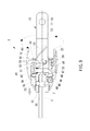
- FIG. 7 is another cross-sectional view of the chuck shown in FIG. 6 ;
- FIG. 8 is a cross-sectional view of the chuck shown in FIG. 4 , with various bits shown in phantom lines;
- FIG. 9 is a cross-sectional view of the chuck in another position than shown in FIG. 8 , with one of the bits inserted in the chuck.
- a tool includes a handle 1 and a chuck 2 according to the preferred embodiment of the present invention.
- a portion of the chuck 2 is inserted in and secured to the handle 1 .
- Various bits can be held by the chuck 2 .
- the chuck 2 includes a mandrel 10 , a movable sleeve 40 , a rotary sleeve 50 , a knob 60 and a skin 70 .
- the mandrel 10 includes an insert 12 and a holder 20 .
- the insert 12 includes an annular groove 14 defined therein near the holder 20 .
- the insert 12 further includes a flat end 11 far away from the holder 20 and an aperture 13 defined in the flat end 11 .
- the diameter of the holder 20 is larger than that of the insert 12 .
- the holder 20 includes a cavity 25 axially defined therein.
- the cavity 25 is non-circular and preferably hexagonal in a front view such as FIG. 2 .
- the holder 20 further includes a slit 24 defined therein, thus dividing the holder 20 into two branches that can be forced towards each other.
- the holder 20 further includes bores 21 and 22 transversely defined therein. Both of the bores 21 and 22 are in communication with the slit 24 .
- the bore 22 is preferably a countersink hole with an annular shoulder formed between large and small sections.
- a bore 23 is defined in one of the branches of the holder 20 .
- the bore 23 is in communication with the cavity 25 .
- the holder 20 includes a groove 26 defined in the other branch thereof. The groove 26 is separated from the cavity 25 .
- the movable sleeve 40 can be moved axially but cannot be rotated relative to the other elements of the chuck 2 .
- the movable sleeve 40 includes a thread 41 formed on a section and a pusher 42 formed on an opposite section.
- the movable sleeve 40 includes a bore 43 axially defined therein.
- the movable sleeve 40 further includes, on an internal face thereof, three cylindrical faces 44 , 48 and 49 , an annular groove 45 next to the cylindrical face 44 , and an annular slope 47 between the cylindrical faces 48 and 49 .
- the diameter of the cylindrical face 48 is larger than that of the cylindrical face 49 .
- the pusher 42 includes a slit 54 defined therein, thus dividing the pusher 42 into two branches.
- a screw hole 46 is transversely defined in one of the branches of the pusher 42 so that the screw hole 46 is in communication with the bore 43 .
- the rotary sleeve 50 includes an engagement face 51 on the outside and a thread 52 on the inside.
- the engagement face 51 is non-circular and preferably polygonal when it is viewed along an axis thereof.
- the rotary sleeve 50 further includes an annular flange 53 on the inside at one of two open ends thereof.
- the knob 60 includes an annular recess 61 on the outside, an annular shoulder 62 on the inside, and an engagement face 63 on the inside.
- the engagement face 63 is non-rotational and preferably polygonal when it is viewed along an axis thereof corresponding to the engagement face 51 .
- the skin 70 includes an anti-skid face 71 on the outside and a smooth face 72 on the inside.
- the anti-skid face 71 includes ribs formed thereon.
- the insert 12 is inserted in the handle 1 when the handle 1 is molded. Some of the material of the handle 1 filled in the aperture 13 . Thus, the chuck 2 is secured to the handle 1 when the material is cured. Because of the flat end 11 of the insert 12 , the chuck 2 can only be rotated together with the handle 1 .
- a rod 34 is inserted in the slit 24 via the bore 21 .
- a pin 30 is formed with a head 31 and a body 32 . The diameter of the head 31 is larger than the diameter of the body 32 .
- the body 32 of the pin 30 is inserted in the bore 22 through a helical spring 33 .
- the helical spring 33 is compressed between the head 31 of the pin 30 and the shoulder formed in the bore 22 so that the body 32 of the pin 30 is retained outside the slit 24 .
- the body 32 of the pin 30 can be inserted into the slit 24 .
- a ball 35 is inserted in the cavity 25 through the bore 23 .
- the rotary sleeve 50 is provided around the mandrel 10 .
- the annular flange 53 of the rotary sleeve 50 is located against an annular shoulder formed between the insert 11 and the holder 20 .
- a C-clip 15 is located in the annular groove 14 .
- the movable sleeve 40 is located around the mandrel 10 .
- the thread 41 of the movable sleeve 40 is engaged with the thread 52 of the rotary sleeve 50 .
- the head 31 of the pin 30 is located against the cylindrical face 48 of the movable sleeve 40 .
- the head 31 of the pin 30 may or may not be located against the annular slope 47 of the movable sleeve 40 .
- a portion of the ball 35 can be moved into the annular groove 45 of the movable sleeve 40 .
- a screw 36 is driven in the groove 26 of the holder 20 via the screw hole 46 of the movable sleeve 40 .
- the movable sleeve 40 is prevented from rotation around the holder 20 but allowed to move along the holder 20 when the rotary sleeve 50 is rotated.
- the knob 60 is located around the rotary sleeve 50 .
- the engagement face 63 of the knob 60 is in firm contact with the engagement face 51 of the rotary sleeve 50 .
- the knob 60 can be fit on the rotary sleeve 50 or adhesive can be provided between the engagement faces 63 and 51 .
- the annular shoulder 62 of knob 60 is located against an end of the rotary sleeve 50 .
- the skin 70 is located in the annular recess 61 of the knob 60 .
- the skin 70 can be fit in the annular recess 61 or adhesive can be provided between the skin 70 and the knob 60 .
- each of the saws A includes an aperture B defined therein near an end. The end of each of the saws A can be inserted into the slit 24 because the body 32 of the pin 30 is located outside the slit 24 .
- the aperture B of the saw A is aligned with the bore 22 when the end of the saw A is located against the rod 34 .
- the rotary sleeve 50 is rotated so that the movable sleeve 40 is moved along the mandrel 10 .
- the tip of the pin 30 is inserted into the aperture B of the saw A as the head 31 of the pin 30 is pushed by the annular slope 47 .
- the saw A is sandwiched between an annular shoulder formed on the body 32 of the pin 30 and one of the branches of the holder 20 .
- the saw A is firmly held with the chuck 2 .
- the four bits include two screwdrivers C, a socket D and a file E.
- Each of the bits includes an annular groove F or several recesses F defined therein near an end. The end of each of the bits can be inserted into the cavity 25 of the holder 20 because the ball 35 can be moved out of the cavity 25 completely as the ball 35 can be moved into the annular groove 45 of the movable sleeve 40 partially.
- the annular groove F or one of the recesses F of the bit is aligned with the bore 23 when the end of the bit is located against a closed end of the cavity 25 .
- the rotary sleeve 50 is rotated so that the movable sleeve 40 is moved along the mandrel 10 .
- a portion of the ball 35 is inserted into the annular groove or recess F of the bit as an opposite portion of the ball 35 is pushed by the cylindrical face 44 of the movable sleeve 40 .
- the bit is held with the chuck 2 .
Landscapes
- Engineering & Computer Science (AREA)
- Mechanical Engineering (AREA)
- Details Of Spanners, Wrenches, And Screw Drivers And Accessories (AREA)
Abstract
Description
Claims (17)
Priority Applications (1)
| Application Number | Priority Date | Filing Date | Title |
|---|---|---|---|
| US12/764,952 US8622400B2 (en) | 2010-04-22 | 2010-04-22 | Quick and reliable tool |
Applications Claiming Priority (1)
| Application Number | Priority Date | Filing Date | Title |
|---|---|---|---|
| US12/764,952 US8622400B2 (en) | 2010-04-22 | 2010-04-22 | Quick and reliable tool |
Publications (2)
| Publication Number | Publication Date |
|---|---|
| US20110260415A1 US20110260415A1 (en) | 2011-10-27 |
| US8622400B2 true US8622400B2 (en) | 2014-01-07 |
Family
ID=44815140
Family Applications (1)
| Application Number | Title | Priority Date | Filing Date |
|---|---|---|---|
| US12/764,952 Active 2032-11-07 US8622400B2 (en) | 2010-04-22 | 2010-04-22 | Quick and reliable tool |
Country Status (1)
| Country | Link |
|---|---|
| US (1) | US8622400B2 (en) |
Cited By (4)
| Publication number | Priority date | Publication date | Assignee | Title |
|---|---|---|---|---|
| US20130247392A1 (en) * | 2012-03-20 | 2013-09-26 | Milwaukee Electric Tool Corporation | Reciprocating saw blade clamp |
| US20140015205A1 (en) * | 2011-03-29 | 2014-01-16 | Føvling Træbyg Aps | Power tool adaptor and a reversible tool bit holder adapted for a power tool adaptor |
| US9908220B2 (en) * | 2015-08-17 | 2018-03-06 | Worthtek Co. Ltd. | Detachable tool assembly for screwdriver |
| US11065698B2 (en) | 2018-06-14 | 2021-07-20 | Milwaukee Electric Tool Corporation | Blade clamp for reciprocating saw |
Families Citing this family (11)
| Publication number | Priority date | Publication date | Assignee | Title |
|---|---|---|---|---|
| US9630307B2 (en) | 2012-08-22 | 2017-04-25 | Milwaukee Electric Tool Corporation | Rotary hammer |
| US9890608B2 (en) * | 2012-10-23 | 2018-02-13 | M-I L.L.C. | Mechanical shaft coupling for fluid system connections |
| US20140197609A1 (en) * | 2013-01-16 | 2014-07-17 | A-Tina Tools Co., Ltd. | Hand Tool Plate Clamp |
| US11007631B2 (en) | 2014-01-15 | 2021-05-18 | Milwaukee Electric Tool Corporation | Bit retention assembly for rotary hammer |
| US20160327077A1 (en) * | 2015-05-08 | 2016-11-10 | Shun-Yee Industrial Co., Ltd. | Quick release device of hand tool |
| US10919132B2 (en) | 2015-05-08 | 2021-02-16 | Shun-Yee Industrial Co., Ltd. | Quick release device of hand tool |
| TWM515920U (en) * | 2015-07-09 | 2016-01-21 | 鑽全實業股份有限公司 | Pneumatic saw clamping device |
| US10265082B2 (en) | 2015-08-31 | 2019-04-23 | Medtronic Ps Medical, Inc. | Surgical burs |
| US11076871B2 (en) | 2016-08-31 | 2021-08-03 | Medtronic Ps Medical, Inc. | Multiple connection drive shaft |
| US10814410B1 (en) * | 2019-06-18 | 2020-10-27 | Zheng Kai Hardware Products (Nantong) Co., Ltd. | Saw blade hand tool structure |
| WO2024102642A1 (en) * | 2022-11-10 | 2024-05-16 | Peleton Surgical, Llc | Coupling mechanism for oscillating tool |
Citations (13)
| Publication number | Priority date | Publication date | Assignee | Title |
|---|---|---|---|---|
| US2481945A (en) * | 1944-10-30 | 1949-09-13 | Springfield Detail & Machine P | Toolholding chuck |
| US4571132A (en) * | 1982-06-17 | 1986-02-18 | Bunge Lothar P | Collet assembly |
| US5996452A (en) * | 1998-10-13 | 1999-12-07 | Chiang; Shu Chi | Chuck device for power tool |
| US6511268B1 (en) * | 1999-08-13 | 2003-01-28 | Maxtech Manufacturing Inc. | Tool device with reversible drill bit/screw bit |
| US6808182B2 (en) * | 2002-12-27 | 2004-10-26 | Zangzhou I Con Machinery Co., Ltd. | Quick release or connect chuck device |
| US6874791B2 (en) * | 2003-05-23 | 2005-04-05 | Tsai-Ching Chen | Chuck apparatus |
| US6877751B2 (en) * | 2003-03-27 | 2005-04-12 | Chiu Yung Hsing | Insertable tool connector |
| US7097398B2 (en) * | 2003-11-14 | 2006-08-29 | Alltrade Tools Llc | Multi-functional bit & connect-disconnect coupling used therewith |
| US7407349B2 (en) * | 2004-07-15 | 2008-08-05 | Heinz Kaiser Ag | Boring tool |
| US7669860B2 (en) * | 2006-07-27 | 2010-03-02 | Hsin Ying Enterprise Co., Ltd. | Tool retaining or connecting device |
| US7845428B2 (en) * | 2005-05-31 | 2010-12-07 | Yukiwa Seiko Kabushiki Kaisha | Rotating tool |
| US7871080B2 (en) * | 2004-01-16 | 2011-01-18 | Robert Bosch Gmbh | Tool-less blade clamping apparatus for a reciprocating tool |
| US7922180B2 (en) * | 2006-11-23 | 2011-04-12 | Chi-Fen Meng | Device for locking and releasing a screw bit |
-
2010
- 2010-04-22 US US12/764,952 patent/US8622400B2/en active Active
Patent Citations (13)
| Publication number | Priority date | Publication date | Assignee | Title |
|---|---|---|---|---|
| US2481945A (en) * | 1944-10-30 | 1949-09-13 | Springfield Detail & Machine P | Toolholding chuck |
| US4571132A (en) * | 1982-06-17 | 1986-02-18 | Bunge Lothar P | Collet assembly |
| US5996452A (en) * | 1998-10-13 | 1999-12-07 | Chiang; Shu Chi | Chuck device for power tool |
| US6511268B1 (en) * | 1999-08-13 | 2003-01-28 | Maxtech Manufacturing Inc. | Tool device with reversible drill bit/screw bit |
| US6808182B2 (en) * | 2002-12-27 | 2004-10-26 | Zangzhou I Con Machinery Co., Ltd. | Quick release or connect chuck device |
| US6877751B2 (en) * | 2003-03-27 | 2005-04-12 | Chiu Yung Hsing | Insertable tool connector |
| US6874791B2 (en) * | 2003-05-23 | 2005-04-05 | Tsai-Ching Chen | Chuck apparatus |
| US7097398B2 (en) * | 2003-11-14 | 2006-08-29 | Alltrade Tools Llc | Multi-functional bit & connect-disconnect coupling used therewith |
| US7871080B2 (en) * | 2004-01-16 | 2011-01-18 | Robert Bosch Gmbh | Tool-less blade clamping apparatus for a reciprocating tool |
| US7407349B2 (en) * | 2004-07-15 | 2008-08-05 | Heinz Kaiser Ag | Boring tool |
| US7845428B2 (en) * | 2005-05-31 | 2010-12-07 | Yukiwa Seiko Kabushiki Kaisha | Rotating tool |
| US7669860B2 (en) * | 2006-07-27 | 2010-03-02 | Hsin Ying Enterprise Co., Ltd. | Tool retaining or connecting device |
| US7922180B2 (en) * | 2006-11-23 | 2011-04-12 | Chi-Fen Meng | Device for locking and releasing a screw bit |
Cited By (8)
| Publication number | Priority date | Publication date | Assignee | Title |
|---|---|---|---|---|
| US20140015205A1 (en) * | 2011-03-29 | 2014-01-16 | Føvling Træbyg Aps | Power tool adaptor and a reversible tool bit holder adapted for a power tool adaptor |
| US9604350B2 (en) * | 2011-03-29 | 2017-03-28 | Fovling Traebyg Aps | Power tool adaptor and a reversible tool bit holder adaptor for a power tool adaptor |
| US20130247392A1 (en) * | 2012-03-20 | 2013-09-26 | Milwaukee Electric Tool Corporation | Reciprocating saw blade clamp |
| US9156097B2 (en) * | 2012-03-20 | 2015-10-13 | Milwaukee Electric Tool Corporation | Reciprocating saw blade clamp |
| US9908220B2 (en) * | 2015-08-17 | 2018-03-06 | Worthtek Co. Ltd. | Detachable tool assembly for screwdriver |
| US11065698B2 (en) | 2018-06-14 | 2021-07-20 | Milwaukee Electric Tool Corporation | Blade clamp for reciprocating saw |
| US11786984B2 (en) | 2018-06-14 | 2023-10-17 | Milwaukee Electric Tool Corporation | Blade clamp for reciprocating saw |
| US12275076B2 (en) | 2018-06-14 | 2025-04-15 | Milwaukee Electric Tool Corporation | Blade clamp for reciprocating saw |
Also Published As
| Publication number | Publication date |
|---|---|
| US20110260415A1 (en) | 2011-10-27 |
Similar Documents
| Publication | Publication Date | Title |
|---|---|---|
| US8622400B2 (en) | Quick and reliable tool | |
| CN101823252B (en) | thread guide | |
| US8308168B2 (en) | Quick change tool bit holder | |
| US8721234B2 (en) | Depth gauge for drill bit | |
| US10035197B2 (en) | Quick change system for rotary tools | |
| US10343266B2 (en) | Bit holder assembly | |
| US9199363B2 (en) | Wrench device | |
| US20080184852A1 (en) | Multi-Bit Drive With Drive Guide | |
| US9579731B2 (en) | Drill chuck assembly | |
| US11173585B2 (en) | Shaft securing mechanism | |
| JP2017533108A (en) | System for releasably connecting a hole saw to a drill shaft | |
| CN108290226A (en) | Locking chuck | |
| US20150102567A1 (en) | Tool joint | |
| US10556276B2 (en) | Locking chuck | |
| US7404563B2 (en) | Reversible drill and drive tool II | |
| US8479620B2 (en) | Torque-setting device | |
| US20170057063A1 (en) | Insert bit | |
| US9868195B2 (en) | Hand tool assembly | |
| US20170173766A1 (en) | Power tool adapter | |
| US20100207335A1 (en) | Tool with a Chuck | |
| US12337449B2 (en) | Foreign object removal socket adapter | |
| US20190375090A1 (en) | Joint for a swing wrench | |
| US20150101461A1 (en) | Driving tool combination | |
| US12109633B1 (en) | Integrated toolless clamp | |
| US9636754B2 (en) | Reamer |
Legal Events
| Date | Code | Title | Description |
|---|---|---|---|
| AS | Assignment |
Owner name: YIH CHENG FACTORY CO., LTD, TAIWAN Free format text: ASSIGNMENT OF ASSIGNORS INTEREST;ASSIGNOR:LIN, JACK;REEL/FRAME:024743/0420 Effective date: 20100305 |
|
| STCF | Information on status: patent grant |
Free format text: PATENTED CASE |
|
| FPAY | Fee payment |
Year of fee payment: 4 |
|
| MAFP | Maintenance fee payment |
Free format text: PAYMENT OF MAINTENANCE FEE, 8TH YR, SMALL ENTITY (ORIGINAL EVENT CODE: M2552); ENTITY STATUS OF PATENT OWNER: SMALL ENTITY Year of fee payment: 8 |
|
| MAFP | Maintenance fee payment |
Free format text: PAYMENT OF MAINTENANCE FEE, 12TH YR, SMALL ENTITY (ORIGINAL EVENT CODE: M2553); ENTITY STATUS OF PATENT OWNER: SMALL ENTITY Year of fee payment: 12 |