US8621879B2 - Air conditioning system recharging method and apparatus - Google Patents
Air conditioning system recharging method and apparatus Download PDFInfo
- Publication number
- US8621879B2 US8621879B2 US12/718,038 US71803810A US8621879B2 US 8621879 B2 US8621879 B2 US 8621879B2 US 71803810 A US71803810 A US 71803810A US 8621879 B2 US8621879 B2 US 8621879B2
- Authority
- US
- United States
- Prior art keywords
- refrigerant
- air conditioning
- conditioning system
- pulse period
- amount
- Prior art date
- Legal status (The legal status is an assumption and is not a legal conclusion. Google has not performed a legal analysis and makes no representation as to the accuracy of the status listed.)
- Active, expires
Links
Images


Classifications
-
- B—PERFORMING OPERATIONS; TRANSPORTING
- B60—VEHICLES IN GENERAL
- B60H—ARRANGEMENTS OF HEATING, COOLING, VENTILATING OR OTHER AIR-TREATING DEVICES SPECIALLY ADAPTED FOR PASSENGER OR GOODS SPACES OF VEHICLES
- B60H1/00—Heating, cooling or ventilating devices
- B60H1/00507—Details, e.g. mounting arrangements, desaeration devices
- B60H1/00585—Means for monitoring, testing or servicing the air-conditioning
-
- F—MECHANICAL ENGINEERING; LIGHTING; HEATING; WEAPONS; BLASTING
- F25—REFRIGERATION OR COOLING; COMBINED HEATING AND REFRIGERATION SYSTEMS; HEAT PUMP SYSTEMS; MANUFACTURE OR STORAGE OF ICE; LIQUEFACTION SOLIDIFICATION OF GASES
- F25B—REFRIGERATION MACHINES, PLANTS OR SYSTEMS; COMBINED HEATING AND REFRIGERATION SYSTEMS; HEAT PUMP SYSTEMS
- F25B45/00—Arrangements for charging or discharging refrigerant
-
- F—MECHANICAL ENGINEERING; LIGHTING; HEATING; WEAPONS; BLASTING
- F25—REFRIGERATION OR COOLING; COMBINED HEATING AND REFRIGERATION SYSTEMS; HEAT PUMP SYSTEMS; MANUFACTURE OR STORAGE OF ICE; LIQUEFACTION SOLIDIFICATION OF GASES
- F25B—REFRIGERATION MACHINES, PLANTS OR SYSTEMS; COMBINED HEATING AND REFRIGERATION SYSTEMS; HEAT PUMP SYSTEMS
- F25B2345/00—Details for charging or discharging refrigerants; Service stations therefor
- F25B2345/001—Charging refrigerant to a cycle
-
- F—MECHANICAL ENGINEERING; LIGHTING; HEATING; WEAPONS; BLASTING
- F25—REFRIGERATION OR COOLING; COMBINED HEATING AND REFRIGERATION SYSTEMS; HEAT PUMP SYSTEMS; MANUFACTURE OR STORAGE OF ICE; LIQUEFACTION SOLIDIFICATION OF GASES
- F25B—REFRIGERATION MACHINES, PLANTS OR SYSTEMS; COMBINED HEATING AND REFRIGERATION SYSTEMS; HEAT PUMP SYSTEMS
- F25B2345/00—Details for charging or discharging refrigerants; Service stations therefor
- F25B2345/003—Control issues for charging or collecting refrigerant to or from a cycle
Definitions
- the present invention relates generally to methods for charging and/or recharging air conditioning systems.
- the present invention also relates generally to devices and/or systems for charging and/or recharging air conditioning systems.
- Air conditioning systems are currently commonplace in homes, office buildings and a variety of vehicles including, for example, automobiles. Over time, the refrigerant included in these systems often gets depleted and/or contaminated. As such, in order to maintain the overall efficiency and efficacy of the air conditioning system, the refrigerant may be periodically recharged.
- recharging air conditioning systems typically include placing refrigerant in a recharging unit, connecting the recharging unit to an air conditioning system and transferring the refrigerant from the recharging unit to the air conditioning system. More specifically, some currently available recharging units include a refrigerant-containing reservoir, a scale that supports and monitors how much refrigerant is in the reservoir and a valve that regulates the rate at which the refrigerant flows out of the reservoir.
- such a recharging unit initially charges the air conditioning system to within a certain amount of the optimal (e.g., manufacturer recommended) charge amount for the air conditioning system in question. Then, the recharging unit continues the charging process by periodically opening the valve in short pulses of a predetermined length. Subsequent to each pulse, a scale reading is taken and the amount of refrigerant that has been transferred out of the reservoir is determined. These pulses continue until the optimal charge for the air conditioning system in question has been achieved.
- the optimal charge amount for the air conditioning system in question has been achieved.
- the above-discussed recharging systems and methods have proven to be relatively accurate but also relatively slow. This is particularly true as the target level of charge is approached since the pressures in the reservoir and in the air conditioning system sometimes nearly equalize. As such, in some instances, the recharging unit may pulse for one minute or more. In other instances, due at least in part to the ideal-gas-law-related changes in temperature associated with pressure changes as the refrigerant enters the air conditioning system and exits the recharging unit, the recharging unit may never attain the target level of charge.
- a method of charging an air conditioning system includes determining a desired amount of refrigerant to be used in the air conditioning system and transferring less than the desired amount of the refrigerant to the air conditioning system.
- the method also includes adding an incremental amount of the refrigerant to the air conditioning system during an initial pulse period and dividing a value representing a remaining amount of the refrigerant needed to attain the desired amount by a value representing the incremental amount of the refrigerant to obtain a result.
- the method further includes multiplying the result by the initial pulse period to determine a subsequent pulse period and adding a subsequent incremental amount of the refrigerant to the air conditioning system during the subsequent pulse period.
- an air conditioning recharging system in accordance with another embodiment of the present invention, includes a refrigerant reservoir configured to contain a refrigerant and a sensor configured to monitor how much of the refrigerant is in the reservoir.
- the system also includes an input device configured to receive information about a desired amount of the refrigerant to be used in an air conditioning system of a vehicle and a connector configured to be attached to the air conditioning system of the vehicle and to transfer the refrigerant to the air conditioning system.
- the system further includes a valve configured to control flow of the refrigerant between the recharging system and the air conditioning system, an actuator configured to control the valve and a processor that is in communication with the input device, the sensor and the actuator.
- the processor is configured to signal the actuator to open the valve for an initial loading period such that less than the desired amount of the refrigerant is transferred to the air conditioning system.
- the processor is also configured to signal the actuator to open the valve for an initial pulse period such that an incremental amount of the refrigerant is added to the air conditioning system.
- the processor is further configured to obtain information from the sensor regarding how much of the refrigerant was transferred to the air conditioning system during the initial loading period and during the initial pulse period.
- the processor is also configured to divide a value representing a remaining amount of the refrigerant needed to attain the desired amount by a value representing the incremental amount of the refrigerant to obtain a result.
- the processor is also configured to multiply the result by the initial pulse period to determine a subsequent pulse period and to signal the actuator to open the valve for the subsequent pulse period such that a subsequent incremental amount of the refrigerant has been added to the air conditioning system.
- another air conditioning recharging system includes means for determining a desired amount of refrigerant to be used in an air conditioning system and means for transferring less than the desired amount of the refrigerant to the air conditioning system.
- the system also includes means for adding an incremental amount of the refrigerant to the air conditioning system during an initial pulse period and means for dividing a value representing a remaining amount of the refrigerant needed to attain the desired amount by a value representing the incremental amount of the refrigerant to obtain a result.
- the system includes means for multiplying the result by the initial pulse period to determine a subsequent pulse period and means for adding a subsequent incremental amount of the refrigerant to the air conditioning system during the subsequent pulse period.
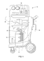
- FIG. 1 is a schematic representation of an air conditioning recharging system according to one embodiment of the present invention.
- FIG. 2 is an illustration of the air conditioning recharging system illustrated in FIG. 1 as connected to a vehicle.
- FIG. 3 is a flowchart illustrating steps of a method of charging an air conditioning system according an embodiment of the present invention.
- FIG. 1 is a schematic representation of an air conditioning recharging system 10 according to one embodiment of the present invention.
- the recharging system 10 includes a refrigerant reservoir 12 , a sensor 14 , an input device 16 , a connector 18 , a valve 20 , an actuator 22 and a processor 24 .
- FIG. 2 illustrates the air conditioning recharging system 10 illustrated in FIG. 1 as it is connected to a vehicle 26 via a pair of hoses 28 .
- the refrigerant reservoir 12 illustrated in FIG. 1 is configured to contain a refrigerant. No limitations are placed on the kind of refrigerant that may be used according to the present invention. As such, any refrigerant that is commonly available (e.g., R-134a) may be added to the reservoir 12 . However, according to certain embodiments of the present invention, the reservoir 12 is particularly configured to accommodate refrigerants that are commonly used in the air conditioning systems of vehicles (e.g., cars, trucks, boats, etc.).
- vehicles e.g., cars, trucks, boats, etc.
- the above-mentioned sensor 14 is configured to monitor how much refrigerant is contained in the reservoir 12 at a given time.
- the sensor 14 may take the form of a scale upon which the reservoir 12 sits.
- calculating how much refrigerant is in the reservoir 12 based upon weight is a straightforward calculation.
- other embodiments of the invention allow for other types of sensors to be used. For example, a flow meter may be used to monitor how much refrigerant is transferred out of the reservoir 12 .
- the input device 16 illustrated in FIG. 1 is configured to receive information about a desired amount of the refrigerant to be used in the air conditioning system of the vehicle 26 illustrated in FIG. 2 .
- this desired amount coincides with the manufacturer's recommended operating amount for the air conditioning system in question. This value may typically be found at least in the air conditioning system's technical manual.
- the input device 16 When the input device 16 takes the form of a keypad as illustrated in FIG. 1 , an operator of the recharging system 10 (e.g., a mechanic) may, for example, simply type in the desired amount after looking it up in the technical manual.
- the input device 16 includes a data port used to download information about a wide array of vehicles to the system 10 .
- the downloaded information is stored within a memory device included in the recharging system 10 .
- the mechanic uses the keypad to select the parameters of the vehicle 26 (e.g., make, model, year) and the recharging system 10 determines the desired amount internally.
- the input device 16 is electronically connected to the on-board computer of the vehicle 26 and the on-board computer informs the recharging system of the value of the desired amount.
- the connector 18 is configured to be attached to the air conditioning system of the vehicle 26 and to transfer the refrigerant from the reservoir 12 to the air conditioning system.
- One or more extensions e.g., the hoses 28 illustrated in FIG. 2 ) may be connected to the connector 18 .
- this promotes convenient, safe and effective flow of the refrigerant from the recharging system 10 to the air conditioning system of the vehicle 26 .
- the valve 20 illustrated in FIG. 1 is configured to control flow of the refrigerant between the recharging system 10 and the air conditioning system of the vehicle 26 .
- the valve 20 is a solenoid valve.
- the use of other types of valves and/or the use of systems including multiple valves is also within the scope of the present invention.
- the actuator 22 illustrated in FIG. 1 is configured to control the valve 20 also illustrated therein.
- the actuator 22 may control either portions of or the entire system.
- FIG. 1 also illustrates a processor 24 that is in communication with the input device 16 , the sensor 14 and the actuator 22 .
- the processor 24 communicates with (e.g., obtains information from) the input device 16 and/or the sensor 14 and controls the actuator 26 , thereby effectively also controlling any valves 26 included in the recharging system 10 .
- No particular restrictions are placed on the circuitry that may be used to implement the processor 24 , so long as the processor 24 is capable of communicating and/or controlling with the input device 16 , sensor 14 and actuator 22 .
- the processor 24 is configured to be able to implement one or more steps of methods of charging/recharging air conditioning systems according to the present invention, including those discussed below.
- FIG. 3 is a flowchart 30 illustrating the steps of a method of charging an air conditioning system according to an embodiment of the present invention. According to certain embodiments of the present invention, one or more of the steps included in the flowchart 30 may be implemented using components contained within the air conditioning recharging system 10 illustrated in FIGS. 1 and 2 , particularly by the processor 24 .
- the first step of the flowchart in FIG. 3 specifies determining the desired amount of refrigerant to be used in the air conditioning system that is being charged or recharged. As discussed above, the desired amount typically coincides with the air conditioning system manufacture's recommended amount for optimal performance. According to certain embodiments of the present invention, the implementation of step 32 includes obtaining information about the desired amount of refrigerant from an outside source (e.g., a vehicle's on-board computer or a technical manual offered by the manufacturer of the air conditioning system).
- an outside source e.g., a vehicle's on-board computer or a technical manual offered by the manufacturer of the air conditioning system.
- the second step of the flowchart specifies transferring less than the desired amount of the refrigerant to the air conditioning system.
- step 34 is implemented by transferring approximately 5% less than the desired amount of refrigerant into the air conditioning system.
- the transferring step 34 includes transferring approximately 27 grams less than the desired amount to the air conditioning system.
- certain embodiments of the present invention utilize the transferring step 34 to add refrigerant to the air conditioning system of a vehicle (e.g., an automobile, a truck, a boat, an airplane), this is not particularly limiting of the present invention. Rather, the scope of the present invention also includes the charging and/or recharging of air conditioning systems of more static items (e.g., homes, commercial buildings, etc.).
- a vehicle e.g., an automobile, a truck, a boat, an airplane
- the scope of the present invention also includes the charging and/or recharging of air conditioning systems of more static items (e.g., homes, commercial buildings, etc.).
- Step 36 of the flowchart 30 which is typically performed after step 34 has been performed, specifies adding an incremental amount of the refrigerant to the above-mentioned air conditioning system during an initial pulse period.
- the initial pulse period is selected to be substantially equal to or less than 100 milliseconds.
- the initial pulse period is sometimes selected to be substantially equal to or less than 18 milliseconds.
- the adding step 36 sometimes includes transferring the refrigerant to the air conditioning system from a container (e.g., the refrigerant reservoir 12 illustrated in FIG. 1 ) that is positioned upon a weighing device (e.g., the sensor 14 also illustrated in FIG. 1 ).
- Step 38 of the flowchart 30 next specifies pausing pursuant to step 36 .
- this pause allows the above-mentioned weighing device to more accurately weigh the container.
- the refrigerant remaining in the refrigerant reservoir 12 is allowed to settle.
- this pause may be for less than 1 second and may sometimes be on the order of tens or hundreds of milliseconds, other pause lengths (including no pause at all), are also within the scope of the present invention.
- the processor 24 may signal the actuator 22 to open the valve 20 for an initial loading period such that less than the desired amount of the refrigerant (e.g., 27 grams less than the desired amount) gets transferred to the air conditioning system of the vehicle 26 illustrated in FIG. 2 . Then, the processor 24 may signal the actuator 22 to open the valve for an initial pulse period (e.g., 18 milliseconds) such that an incremental amount of the refrigerant is added to the air conditioning system. Afterwards, the processor 24 may obtain information from the sensor 14 regarding how much of the refrigerant was transferred to the air conditioning system during the initial transferring/loading period and during the subsequent initial pulse period. At least some of this information may be obtained pursuant to the above-mentioned pause period to increase sensor accuracy.
- the desired amount of the refrigerant e.g., 27 grams less than the desired amount
- the processor 24 may signal the actuator 22 to open the valve for an initial pulse period (e.g., 18 milliseconds) such that an incremental amount of the refrigerant
- Step 40 of FIG. 3 next specifies dividing a value representing a remaining amount of the refrigerant needed to attain the desired amount by a value representing the incremental amount of the refrigerant added during the above-discussed pulse to obtain a result.
- the weight of the additional refrigerant needed to “fill up” the air conditioning system is divided by the weight of the incremental amount of refrigerant that was added during step 36 .
- the processor 24 may be configured to collect the weight data from the sensor 14 and to perform the subsequent division.
- Step 42 of the flowchart 30 next specifies multiplying the result obtained while implementing step 40 by the initial pulse period in order to determine a subsequent pulse period for additional charging.
- steps 40 and 42 may be illustrated via the following equation:
- subsequent_pulse amt_of ⁇ _charge ⁇ _remaining start_wt - finish_wt * initial_pulse
- the processor 24 may be configured to do the above-discussed multiplication.
- step 44 specifies adding a subsequent incremental amount of the refrigerant to the air conditioning system during the subsequent pulse period.
- the processor 24 typically signals the actuator 22 to open the valve 20 for the subsequent pulse period in order to ensure that the subsequent incremental amount of the refrigerant has been added to the air conditioning system of the vehicle 26 .
- a pause period analogous to the one specified in step 38 may be implemented pursuant to step 44 . The primary benefit of this second pause period would again be increasing the accuracy of the subsequent weight reading by the sensor 14 .
- Step 46 next specifies dividing a value representing an updated remaining amount of the refrigerant needed to attain the desired amount by a value representing the subsequent incremental amount to obtain an updated result. Then, step 48 specifies multiplying the updated result by the subsequent pulse period to obtain an updated pulse period and step 50 specifies adding an additional incremental amount of the refrigerant to the air conditioning system during the updated pulse period.
- the processor 24 may be configured to perform the mathematical steps recited in steps 46 and 48 after having received information from the sensor 24 and may implement step 50 by re-signaling the actuator 22 to open the valve 20 for the updated pulse period such that the additional incremental amount of the refrigerant is added to the air conditioning system of the vehicle 26 .
- step 52 questions whether or not the desired amount is at least substantially in the air conditioning system pursuant to step 50 . If the total amount of added refrigerant is at least substantially equal to the desired amount, then the process illustrated in flowchart 30 ends. However, if additional refrigerant needs to be added, then, according to step 54 , the subsequent incremental amount is set equal to the additional incremental amount and steps 44 through 54 are iteratively repeated until the desired amount has been added.
Landscapes
- Engineering & Computer Science (AREA)
- Physics & Mathematics (AREA)
- Mechanical Engineering (AREA)
- Thermal Sciences (AREA)
- General Engineering & Computer Science (AREA)
- Air-Conditioning For Vehicles (AREA)
Abstract
Description
When implementing
Claims (17)
Priority Applications (1)
| Application Number | Priority Date | Filing Date | Title |
|---|---|---|---|
| US12/718,038 US8621879B2 (en) | 2010-03-05 | 2010-03-05 | Air conditioning system recharging method and apparatus |
Applications Claiming Priority (1)
| Application Number | Priority Date | Filing Date | Title |
|---|---|---|---|
| US12/718,038 US8621879B2 (en) | 2010-03-05 | 2010-03-05 | Air conditioning system recharging method and apparatus |
Publications (2)
| Publication Number | Publication Date |
|---|---|
| US20110214436A1 US20110214436A1 (en) | 2011-09-08 |
| US8621879B2 true US8621879B2 (en) | 2014-01-07 |
Family
ID=44530130
Family Applications (1)
| Application Number | Title | Priority Date | Filing Date |
|---|---|---|---|
| US12/718,038 Active 2032-07-19 US8621879B2 (en) | 2010-03-05 | 2010-03-05 | Air conditioning system recharging method and apparatus |
Country Status (1)
| Country | Link |
|---|---|
| US (1) | US8621879B2 (en) |
Families Citing this family (2)
| Publication number | Priority date | Publication date | Assignee | Title |
|---|---|---|---|---|
| AT518500B1 (en) * | 2016-04-13 | 2018-04-15 | Avl Ditest Gmbh | Method and device for filling an air conditioning system with refrigerant |
| CN107720678A (en) * | 2017-10-25 | 2018-02-23 | 湖北省电力装备有限公司 | A kind of central air-conditioning special electric gasoline pump |
Citations (2)
| Publication number | Priority date | Publication date | Assignee | Title |
|---|---|---|---|---|
| US20060101835A1 (en) * | 2004-11-18 | 2006-05-18 | Snap-On Incorporated | Refrigerant charging by optimum performance |
| US20090008859A1 (en) * | 2007-07-02 | 2009-01-08 | Pitney Bowes Incorporated | Multi-segment weight measurement apparatus and method for processing sheet material |
-
2010
- 2010-03-05 US US12/718,038 patent/US8621879B2/en active Active
Patent Citations (2)
| Publication number | Priority date | Publication date | Assignee | Title |
|---|---|---|---|---|
| US20060101835A1 (en) * | 2004-11-18 | 2006-05-18 | Snap-On Incorporated | Refrigerant charging by optimum performance |
| US20090008859A1 (en) * | 2007-07-02 | 2009-01-08 | Pitney Bowes Incorporated | Multi-segment weight measurement apparatus and method for processing sheet material |
Also Published As
| Publication number | Publication date |
|---|---|
| US20110214436A1 (en) | 2011-09-08 |
Similar Documents
| Publication | Publication Date | Title |
|---|---|---|
| US9366465B2 (en) | System and method for improving charge accuracy by temperature compensation | |
| US8516836B2 (en) | System and method for accurately recharging an air conditioning system | |
| EP3040652B1 (en) | System and method for recovering refrigerant | |
| JP5328617B2 (en) | Gas filling system, gas filling method, vehicle | |
| US7966115B2 (en) | System and method for controlling transmission shift points based on vehicle weight | |
| US7310956B2 (en) | Refrigerant charging by optimum performance | |
| US20160116392A1 (en) | System and Method for Estimating Remaining Useful Life of a Filter | |
| US20140377605A1 (en) | Method for estimating the temperature at the core of a battery cell | |
| KR20160130389A (en) | Method for assessing a state of charge of a battery comprising a plurality of cells having a variable range of use of state of charge | |
| DE102010048252B4 (en) | Temperature compensation method for air suspension after engine shutdown | |
| US8621879B2 (en) | Air conditioning system recharging method and apparatus | |
| US7210300B2 (en) | Refrigerant charging system and method with cartridges | |
| US20060101834A1 (en) | Refrigerant charging system and method using vapor-phase refrigerant | |
| GB2505663A (en) | Dynamically variable residual range indicator for motor vehicle | |
| KR101807417B1 (en) | Residual propellant gauging method for geostationary satellites and apparatus therefor | |
| CN112912745A (en) | Method for determining the state of charge and the state of ageing of an electrochemical cell from an open circuit voltage diagram | |
| KR101294354B1 (en) | System for verifying battery modeling using battery hils | |
| US20200391568A1 (en) | Method and device for operating a pneumatic system with a compressed air supply unit and an air spring unit, pneumatic system comprising a compressed air supply unit and an air spring unit, and vehicle | |
| EP2505448A1 (en) | On-board real-time weight prediction system by using CAN data bus | |
| JP7503796B2 (en) | Information processing method, information processing device, and information processing system | |
| EP2881683A1 (en) | System and method for calculating temperature in an air conditioning system | |
| US20060149494A1 (en) | Monitoring of shock absorbers | |
| EP4389497A1 (en) | Usage of vibration data and soh feedback for controlling battery pack vibration | |
| KR101270641B1 (en) | Load amount measuring apparatus for vehicle | |
| US20200370285A1 (en) | State analysis device, state analysis method, and recording medium |
Legal Events
| Date | Code | Title | Description |
|---|---|---|---|
| AS | Assignment |
Owner name: SPX CORPORATION, NORTH CAROLINA Free format text: ASSIGNMENT OF ASSIGNORS INTEREST;ASSIGNORS:BROWN, WILLIAM;MCMASTERS, MARK;REEL/FRAME:024033/0491 Effective date: 20100225 |
|
| AS | Assignment |
Owner name: SERVICE SOLUTIONS U.S. LLC, NORTH CAROLINA Free format text: ASSIGNMENT OF ASSIGNORS INTEREST;ASSIGNOR:SPX CORPORATION;REEL/FRAME:031686/0429 Effective date: 20121130 Owner name: BOSCH AUTOMOTIVE SERVICE SOLUTIONS LLC, MICHIGAN Free format text: CHANGE OF NAME;ASSIGNOR:SERVICE SOLUTIONS U.S. LLC;REEL/FRAME:031737/0668 Effective date: 20130730 |
|
| STCF | Information on status: patent grant |
Free format text: PATENTED CASE |
|
| FPAY | Fee payment |
Year of fee payment: 4 |
|
| MAFP | Maintenance fee payment |
Free format text: PAYMENT OF MAINTENANCE FEE, 8TH YEAR, LARGE ENTITY (ORIGINAL EVENT CODE: M1552); ENTITY STATUS OF PATENT OWNER: LARGE ENTITY Year of fee payment: 8 |
|
| MAFP | Maintenance fee payment |
Free format text: PAYMENT OF MAINTENANCE FEE, 12TH YEAR, LARGE ENTITY (ORIGINAL EVENT CODE: M1553); ENTITY STATUS OF PATENT OWNER: LARGE ENTITY Year of fee payment: 12 |