US8621758B2 - Razor handle - Google Patents
Razor handle Download PDFInfo
- Publication number
- US8621758B2 US8621758B2 US13/767,246 US201313767246A US8621758B2 US 8621758 B2 US8621758 B2 US 8621758B2 US 201313767246 A US201313767246 A US 201313767246A US 8621758 B2 US8621758 B2 US 8621758B2
- Authority
- US
- United States
- Prior art keywords
- gripping
- gripping pad
- frame
- snap fit
- extension
- Prior art date
- Legal status (The legal status is an assumption and is not a legal conclusion. Google has not performed a legal analysis and makes no representation as to the accuracy of the status listed.)
- Active
Links
Images


Classifications
-
- B—PERFORMING OPERATIONS; TRANSPORTING
- B26—HAND CUTTING TOOLS; CUTTING; SEVERING
- B26B—HAND-HELD CUTTING TOOLS NOT OTHERWISE PROVIDED FOR
- B26B21/00—Razors of the open or knife type; Safety razors or other shaving implements of the planing type; Hair-trimming devices involving a razor-blade; Equipment therefor
- B26B21/40—Details or accessories
- B26B21/52—Handles, e.g. tiltable, flexible
- B26B21/522—Ergonomic details, e.g. shape, ribs or rubber parts
-
- B—PERFORMING OPERATIONS; TRANSPORTING
- B26—HAND CUTTING TOOLS; CUTTING; SEVERING
- B26B—HAND-HELD CUTTING TOOLS NOT OTHERWISE PROVIDED FOR
- B26B21/00—Razors of the open or knife type; Safety razors or other shaving implements of the planing type; Hair-trimming devices involving a razor-blade; Equipment therefor
- B26B21/40—Details or accessories
- B26B21/52—Handles, e.g. tiltable, flexible
- B26B21/528—Manufacture of razor handles
Definitions
- This invention relates generally to wet shaving devices, and more specifically to razor handles including hand gripping pads.
- Many modern safety razors include a disposable razor cartridge adapted to be selectively connected to a reusable handle by cartridge support structure therebetween.
- the cartridge includes a housing having at least one razor blade with a sharpened cutting edge disposed therein.
- the handle can be provided with gripping pads having on their exterior surfaces an elastomeric, ie rubber-like material.
- a normal wet shaving operation is typically performed in an environment that can cause a razor handle to be wet and/or slippery due to the shaving soaps or other preparations employed by the user.
- the elastomeric material provides the user with at least a sense of a more secure grip of the handle in these circumstances and can help prevent nicks and cuts that might be caused by the user mishandling the razor or can help prevent the user accidentally dropping the razor.
- Exemplary razors with elastomeric gripping pads are disclosed in U.S. Pat. Nos. 5,822,869 and 5,890,296, both to Metcalf et al. These Patents disclose razor handles having elongated hand-gripping structures that include a frame and at least two gripping pads disposed on opposed sides of the frame. Each gripping pad has a non-elastomeric support layer with an elastomeric gripping layer molded thereon. The support layer of each gripping pad is provided with several extensions that are press fitted into mating elongated slots of the frame to provide the joint between the frame and each respective gripping pad.
- a press fit joint In consideration of the selection of a press fit joint over other suitable joining methods, one of skill in the art will understand that the retention or security of attachment properties of a typical press fit joint are dependent upon several characteristics of the joint including a property of many molded thermoplastics known as creep modulus and the provision a controlled difference in size, or interference, between the extension and one or both sides of its mating slot or opening. Creep modulus can be likened to a time-dependent relaxation effect which can cause the resistance to disengagement of a press fit joint to diminish over an extended time period.
- a controlled interference can provide a somewhat uniform assembly or insertion force of the press fitting parts and is preferred at least for manufacturing reasons.
- So-called commodity thermoplastics of the olefin family such as polypropylene (PP) and derivatives of polyethylene (HDPE, LDPE etc) have desirous properties for a non-elastomeric support layer such as their ability to provide a secure chemical bond to some thermoplastic elastomer (TPE) gripping layers and their preferred ability to withstand chemical attack from some soaps and other shaving preparations.
- TPE thermoplastic elastomer
- the creep moduli of these materials is generally inferior to that of so-called engineering thermoplastics such as ABS, Polyoxymethylene (POM, commonly known as acetal) and other well known materials.
- one component part is provided with an extension with a laterally extending protrusion, usually at or near the distal end portion of the extension.
- the extension undergoes preferably elastic deformation as the lateral protrusion passes around a suitable shelf of the second part before snapping into a mating recess or void of the second part.
- snap fit joints can be permanent or temporary, ie separable and reattachable.
- the present invention has for its objective to eliminate, or at least substantially alleviate the limitations of the prior art by providing a handle for a safety razor having manufacturing advantages provided by an improved joint between a frame and a gripping pad of the handle.
- An embodiment of a handle for a safety razor of the present invention includes an elongated hand gripping structure and a cartridge support structure at an end of the hand gripping structure.
- the elongated hand gripping structure includes a frame structure with at least one opening, a first gripping pad and a second gripping pad.
- Each gripping pad can preferably comprise a thermoplastic elastomeric outer gripping layer formed over a nonelastomeric thermoplastic support layer that is preferably polypropylene.
- the support layer of the first gripping pad has an extension having a snap fit protrusion at its distal end that cooperates with an opening of the frame to provide a snap fit joint between the frame and the first gripping pad.
- the second gripping pad has an extension that cooperates with the extension of the first gripping pad to prevent disengagement of the snap fit from the opening of the frame.
- Embodiments of the present invention include a first gripping pad having a bifurcated extension and the extension of the second gripping pad being partially received in the bifurcation.
- FIG. 1 is a front view of an embodiment of a safety razor of the present invention.
- FIG. 2 is a side view of FIG. 1 .
- FIG. 3A is a sectional view taken along line 3 - 3 of FIG. 1 .
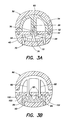
- FIGS. 3B-3D are sectional views of further embodiments of the present invention taken along line 3 - 3 of FIG. 1 .
- a safety razor 10 that includes a razor cartridge 12 connected to a handle 14 .
- the handle includes an elongated hand gripping structure 20 and a cartridge support structure 30 .
- the cartridge support structure preferably provides connection to the razor cartridge such that a user may selectively replace the razor cartridge when he or she finds this appropriate.
- the cartridge is preferably pivotally connected to the support structure so that in use it can pivot about a pivot axis. Particular cartridge support structures including those having pivotal connection are well known to one of skill in the art and the present invention is not limited in this regard.
- the elongated hand gripping structure includes a frame 40 , a first gripping pad 50 and a second gripping pad 70 .
- the frame is preferably manufactured from a die-cast zinc alloy having a suitable metallic plating or painted surface as is well known in the art.
- the frame can also be manufactured from one or more injection molded components, manufactured from a suitable thermoplastic such as ABS or polyamide and the present invention is not limited in regard to the material or manufacture of the frame.
- Each gripping pad 50 , 70 comprises an injection molded nonelastomeric support layer preferably manufactured from a commodity thermoplastic, more preferably polypropylene and most preferably the grade designated KPIC HJ4045 supplied by YUHWA.
- Each gripping pad preferably has a thermoplastic elastomeric (TPE) gripping layer molded over the support layer by any suitable and well known process such as multi-color, also known as multi-shot molding or insert molding.
- TPE thermoplastic elastomeric
- the TPE material is most preferably the grade designated VYRAM 9211-35W-906 supplied by AES.
- the gripping pads are shown disposed on the top and bottom of the hand gripping structure however these may equally be disposed on the left and right side of the hand gripping structure.
- two gripping pads are shown, however more than two gripping pads can equally be employed.
- the second gripping pad 70 could be replaced by two pads, preferably arranged sequentially along the frame and the present invention is not limited in this regard.
- the first gripping pad 50 comprises a support layer 52 and a gripping layer 54 as previously described.
- the second gripping pad 70 comprises a support layer 72 and a gripping layer 74 also as previously described.
- Frame 40 has an opening 42 .
- the first gripping pad 50 has an extension 56 , preferably bifurcated as depicted and having opposed protrusions 58 on the outer surface of the distal end portion of the extension. The bifurcation of the extension 56 provides an opening 60 .
- the bifurcation of the extension preferably provides the distal end portions of the extension with sufficient elasticity to enable protrusions 58 to cooperate with the opening 42 of the frame to provide a well known snap fit joint thereby providing attachment between the frame 40 and the first gripping pad 50 .
- the second gripping pad 70 is subsequently attached to the frame by any suitable and well known means such as by one or more snap fit joints, press fit joints or glue joints.
- the second gripping pad 70 has an extension 76 that at least partially extends into the bifurcation opening 60 of the extension of the first gripping pad.
- extension 76 does not have to undergo deformation during assembly of the second gripping pad it is preferably provided with greater resistance to lateral deformation of its distal end portion than that of the distal end portion of the extension of the first gripping pad. In this manner, the extension of the second gripping pad 76 prevents disengagement of the snap fit joint of the first gripping pad from the frame.
- a press fit joint may also be provided between the extension 76 of the second gripping pad and the opening 60 of the bifurcation of the first gripping pad to provide further security of attachment of each gripping pad to the frame and to each other.
- this disclosure only depicts a single sectional view of the handle of the safety razor taken at the position of line 3 - 3 of FIG. 1 , one of skill in the art will understand that the group of cooperating features described previously can extend along the elongated hand gripping structure and can be a single group or multiple groups of cooperating features.
- FIGS. 3B-3D alternative arrangements of extensions of the first and second gripping pad and cooperating frame opening(s) are depicted in a similar sectional view to that of FIG. 3A .
- extensions 82 of the first gripping pad 80 are depicted spaced apart across the width of the hand gripping structure. Extensions 82 each have a protrusion 84 on the outer surface of the distal end portion of the extension. Extensions 92 of the second gripping pad 90 cooperate with respective extensions of the first gripping pad to prevent disengagement of the snap fit joint between the first gripping pad and the frame 100 , having openings 102 in cooperating relation with protrusions 84 .
- FIG. 3C has a similar arrangement to FIG.
- FIG. 3D depicts protrusion 144 one side only of the centrally disposed extension 142 at the particular position of this sectional view.
- the protrusion can alternate between left and right sides of the extension (as depicted), as the extension extends along the frame of the elongated hand gripping structure.
Abstract
Description
Claims (6)
Priority Applications (1)
| Application Number | Priority Date | Filing Date | Title |
|---|---|---|---|
| US13/767,246 US8621758B2 (en) | 2007-02-01 | 2013-02-14 | Razor handle |
Applications Claiming Priority (3)
| Application Number | Priority Date | Filing Date | Title |
|---|---|---|---|
| US89918507P | 2007-02-01 | 2007-02-01 | |
| US12/020,658 US8424215B2 (en) | 2007-02-01 | 2008-01-28 | Razor handle |
| US13/767,246 US8621758B2 (en) | 2007-02-01 | 2013-02-14 | Razor handle |
Related Parent Applications (1)
| Application Number | Title | Priority Date | Filing Date |
|---|---|---|---|
| US12/020,658 Continuation US8424215B2 (en) | 2007-02-01 | 2008-01-28 | Razor handle |
Publications (2)
| Publication Number | Publication Date |
|---|---|
| US20130152408A1 US20130152408A1 (en) | 2013-06-20 |
| US8621758B2 true US8621758B2 (en) | 2014-01-07 |
Family
ID=39371015
Family Applications (2)
| Application Number | Title | Priority Date | Filing Date |
|---|---|---|---|
| US12/020,658 Active 2029-08-25 US8424215B2 (en) | 2007-02-01 | 2008-01-28 | Razor handle |
| US13/767,246 Active US8621758B2 (en) | 2007-02-01 | 2013-02-14 | Razor handle |
Family Applications Before (1)
| Application Number | Title | Priority Date | Filing Date |
|---|---|---|---|
| US12/020,658 Active 2029-08-25 US8424215B2 (en) | 2007-02-01 | 2008-01-28 | Razor handle |
Country Status (9)
| Country | Link |
|---|---|
| US (2) | US8424215B2 (en) |
| EP (1) | EP2117786B1 (en) |
| JP (1) | JP5220768B2 (en) |
| CN (1) | CN201500997U (en) |
| AT (1) | ATE494994T1 (en) |
| AU (1) | AU2008211271B2 (en) |
| DE (1) | DE602008004451D1 (en) |
| PL (1) | PL2117786T3 (en) |
| WO (1) | WO2008094488A1 (en) |
Cited By (18)
| Publication number | Priority date | Publication date | Assignee | Title |
|---|---|---|---|---|
| USD765912S1 (en) | 2016-03-23 | 2016-09-06 | Phan Thi Minh Vinh | Razor handle |
| KR20160146834A (en) * | 2014-04-16 | 2016-12-21 | 빅-비올렉스 에스아 | Handles for shavers to be releasably connected to shaving cartridges |
| USD802842S1 (en) | 2017-03-15 | 2017-11-14 | Vu Phan Quang Ngo | Safety razor handle |
| USD815776S1 (en) | 2017-10-08 | 2018-04-17 | Vu Phan Quang Ngo | Safety razor |
| USD870382S1 (en) | 2018-03-09 | 2019-12-17 | Personal Care Marketing And Research, Inc. | Razor handle |
| USD870381S1 (en) | 2018-03-09 | 2019-12-17 | Personal Care Marketing And Research, Inc. | Razor handle |
| USD886382S1 (en) | 2018-03-09 | 2020-06-02 | PCMR International Ltd. | Razor handle |
| US11358294B2 (en) | 2018-03-30 | 2022-06-14 | The Gillette Company Llc | Razor handle with movable members |
| US11558931B2 (en) | 2016-06-22 | 2023-01-17 | The Gillette Company Llc | Personal consumer product with thermal control circuitry |
| US11571828B2 (en) | 2018-03-30 | 2023-02-07 | The Gillette Company Llc | Shaving razor handle |
| US11577417B2 (en) | 2018-03-30 | 2023-02-14 | The Gillette Company Llc | Razor handle with a pivoting portion |
| US11607820B2 (en) | 2018-03-30 | 2023-03-21 | The Gillette Company Llc | Razor handle with movable members |
| US11691307B2 (en) | 2018-03-30 | 2023-07-04 | The Gillette Company Llc | Razor handle with a pivoting portion |
| US11766795B2 (en) | 2018-03-30 | 2023-09-26 | The Gillette Company Llc | Razor handle with a pivoting portion |
| US11780105B2 (en) | 2018-03-30 | 2023-10-10 | The Gillette Company Llc | Razor handle with a pivoting portion |
| US11806885B2 (en) | 2018-03-30 | 2023-11-07 | The Gillette Company Llc | Razor handle with movable members |
| US11945128B2 (en) | 2018-03-30 | 2024-04-02 | The Gillette Company Llc | Razor handle with a pivoting portion |
| USD1021248S1 (en) | 2018-03-30 | 2024-04-02 | The Gillette Company Llc | Shaving razor cartridge |
Families Citing this family (20)
| Publication number | Priority date | Publication date | Assignee | Title |
|---|---|---|---|---|
| PL2117786T3 (en) * | 2007-02-01 | 2011-06-30 | Eveready Battery Inc | Razor handle |
| US8186062B2 (en) * | 2007-03-19 | 2012-05-29 | Eveready Battery Company, Inc. | Safety razor with filament guard |
| US8083239B2 (en) | 2008-10-08 | 2011-12-27 | Evolution Technologies Inc. | Foldable walker apparatus |
| US9022413B2 (en) | 2008-10-08 | 2015-05-05 | Evolution Technologies Inc. | Foldable walker apparatus |
| US9415635B2 (en) | 2010-10-29 | 2016-08-16 | Evolution Technologies Inc. | Foldable walker apparatus |
| US8573613B2 (en) | 2010-10-29 | 2013-11-05 | Evolution Technologies Inc. | Foldable walker apparatus |
| US20140230258A1 (en) * | 2013-02-20 | 2014-08-21 | The Gillette Company | Compact hand held device |
| US20140230256A1 (en) * | 2013-02-20 | 2014-08-21 | The Gillette Company | Hand held device |
| US9643327B2 (en) * | 2013-02-20 | 2017-05-09 | The Gillette Company | Wet shaving razor |
| US9180065B2 (en) | 2013-04-15 | 2015-11-10 | Evolution Technologies Inc. | Foldable walker apparatus |
| US9339432B2 (en) | 2014-02-28 | 2016-05-17 | Evolution Technologies Inc. | Walker apparatus and backrest therefor |
| US9744094B2 (en) | 2014-02-28 | 2017-08-29 | Evolution Technologies Inc. | Walker apparatus and backrest therefor |
| US10053062B2 (en) | 2015-09-02 | 2018-08-21 | Evolution Technologies Inc. | Brake assembly for a height-adjustable walker apparatus |
| US10730489B2 (en) | 2015-09-02 | 2020-08-04 | Evolution Technologies Inc. | Brake assembly for height-adjustable patient transport apparatus |
| US11648922B2 (en) | 2015-09-02 | 2023-05-16 | Evolution Technologies Inc. | Manually-operated, height-adjustable wheeled vehicle, and a brake assembly and wheel fork assembly thereof |
| US9844892B2 (en) * | 2016-01-14 | 2017-12-19 | Echo Incorporated | Battery operated chain saw |
| CA167113S (en) | 2016-02-26 | 2017-12-27 | Julian Liu | Set of seat cushions |
| CA173079S (en) | 2017-02-17 | 2017-12-27 | Evolution Tech Inc | Set of seat cushions |
| US10807261B2 (en) * | 2017-06-21 | 2020-10-20 | Harry's, Inc. | Razor handle |
| CN108372520B (en) * | 2018-02-07 | 2023-12-29 | 东莞市港荣五金制品有限公司 | Scissor handle and manufacturing method thereof |
Citations (27)
| Publication number | Priority date | Publication date | Assignee | Title |
|---|---|---|---|---|
| US4281455A (en) * | 1978-10-20 | 1981-08-04 | Wilkinson Sword Limited | Razor with removably mounted pivotal cartridge |
| US4658505A (en) * | 1985-03-15 | 1987-04-21 | Wilkinson Sword Limited | Razor handle for supporting a detachable shaving unit |
| US4801232A (en) * | 1986-04-11 | 1989-01-31 | Camloc Gmbh | Device for the removable fastening of a plate-shaped component onto a base with a T-groove open towards the component |
| US4841638A (en) * | 1987-09-04 | 1989-06-27 | Pumpkin, Ltd. | Hand-held cutting tool apparatus |
| US5027511A (en) | 1990-09-28 | 1991-07-02 | The Gillette Company | Shaving system |
| US5309596A (en) * | 1993-03-23 | 1994-05-10 | The Gillette Company | Interproximal brush |
| US5784790A (en) * | 1996-04-10 | 1998-07-28 | The Gillette Company | Shaving razor and method |
| US5794349A (en) * | 1997-04-01 | 1998-08-18 | Robinson Knife Manufacturing Company, Inc. | Potato and vegetable peeler |
| US5822869A (en) | 1996-04-10 | 1998-10-20 | The Gillette Company | Razor handle |
| US5899824A (en) * | 1997-02-12 | 1999-05-04 | Accudart Corporation | Snap-fit dart and adapter |
| US6108869A (en) | 1996-02-14 | 2000-08-29 | Gillette Canada Inc. | Brush handle |
| US6116807A (en) | 1999-02-02 | 2000-09-12 | Delphi Technologies, Inc. | Rod end retainer socket |
| US6164290A (en) | 1993-02-22 | 2000-12-26 | Andrews; Edward A. | Double-sided safety straight razor |
| US6393704B1 (en) | 2000-05-04 | 2002-05-28 | David Tompkins | Self-leveling eating utensil |
| US20030046780A1 (en) * | 2001-09-11 | 2003-03-13 | Davis Colin G. | Oral care brush |
| US20030172498A1 (en) | 2002-03-15 | 2003-09-18 | Polzin Bruce C. | Apparatus to cushion and dampen vibration and method |
| US20040103545A1 (en) | 2002-08-21 | 2004-06-03 | Eveready Battery Company, Inc. | Razor handle with improved grip |
| US20050019130A1 (en) * | 2002-02-22 | 2005-01-27 | Hideki Kanie | Integrally molded clip and method of forming the same |
| US6886262B2 (en) * | 2002-11-18 | 2005-05-03 | Kai R&D Center Co., Ltd. | Razor and its handle |
| US7114217B2 (en) * | 2003-02-21 | 2006-10-03 | Nifco Inc. | Buffer |
| US20060272154A1 (en) * | 2005-06-02 | 2006-12-07 | Brevard Alfred S | Disposable gel-dispensing razor |
| US20070039151A1 (en) * | 2000-10-30 | 2007-02-22 | Crawley Timothy M | Method and apparatus for replacing gripping member on wire bucket handle |
| US7197825B2 (en) * | 2004-03-11 | 2007-04-03 | The Gillette Company | Razors and shaving cartridges with guard |
| US7497487B2 (en) * | 2004-02-24 | 2009-03-03 | Southco, Inc. | Snap-in latch housing assembly |
| US7736107B2 (en) * | 2004-03-30 | 2010-06-15 | Piolax, Inc. | Clipping device |
| US7740432B2 (en) * | 2006-04-19 | 2010-06-22 | Nifco Inc. | Article installation device |
| US8424215B2 (en) * | 2007-02-01 | 2013-04-23 | Eveready Battery Company, Inc. | Razor handle |
Family Cites Families (11)
| Publication number | Priority date | Publication date | Assignee | Title |
|---|---|---|---|---|
| JPS6039479U (en) * | 1983-08-26 | 1985-03-19 | 株式会社 共立 | handle |
| US4949457A (en) * | 1988-08-03 | 1990-08-21 | Warner-Lambert Company | Soft resilient razor handle |
| DE8911280U1 (en) * | 1989-09-22 | 1991-01-24 | Wilkinson Sword Gmbh, 5650 Solingen, De | |
| JPH04151010A (en) * | 1990-10-11 | 1992-05-25 | Seiko Epson Corp | Engagingly locking structure |
| JPH0490706U (en) * | 1990-12-25 | 1992-08-07 | ||
| US5497551A (en) * | 1994-10-13 | 1996-03-12 | The Gillette Company | Razor handle assembly |
| WO2001094081A1 (en) * | 2000-06-07 | 2001-12-13 | Irega, S.A. | Exchangeable handle for the handles of monkey wrenches |
| JP2004017225A (en) * | 2002-06-18 | 2004-01-22 | Nidec Shibaura Corp | Electric motor tool |
| US20040216311A1 (en) * | 2003-03-28 | 2004-11-04 | Eveready Battery Company, Inc. | Razor handle assembly |
| US7690122B2 (en) * | 2004-03-11 | 2010-04-06 | The Gillette Company | Shaving razor with button |
| JP4598418B2 (en) * | 2004-03-17 | 2010-12-15 | 株式会社貝印刃物開発センター | Safety razor |
-
2008
- 2008-01-28 PL PL08713309T patent/PL2117786T3/en unknown
- 2008-01-28 AU AU2008211271A patent/AU2008211271B2/en active Active
- 2008-01-28 CN CN2008900000211U patent/CN201500997U/en not_active Expired - Lifetime
- 2008-01-28 DE DE602008004451T patent/DE602008004451D1/en active Active
- 2008-01-28 WO PCT/US2008/001066 patent/WO2008094488A1/en active Application Filing
- 2008-01-28 EP EP08713309A patent/EP2117786B1/en active Active
- 2008-01-28 JP JP2009548273A patent/JP5220768B2/en active Active
- 2008-01-28 US US12/020,658 patent/US8424215B2/en active Active
- 2008-01-28 AT AT08713309T patent/ATE494994T1/en not_active IP Right Cessation
-
2013
- 2013-02-14 US US13/767,246 patent/US8621758B2/en active Active
Patent Citations (30)
| Publication number | Priority date | Publication date | Assignee | Title |
|---|---|---|---|---|
| US4281455A (en) * | 1978-10-20 | 1981-08-04 | Wilkinson Sword Limited | Razor with removably mounted pivotal cartridge |
| US4658505A (en) * | 1985-03-15 | 1987-04-21 | Wilkinson Sword Limited | Razor handle for supporting a detachable shaving unit |
| US4801232A (en) * | 1986-04-11 | 1989-01-31 | Camloc Gmbh | Device for the removable fastening of a plate-shaped component onto a base with a T-groove open towards the component |
| US4841638A (en) * | 1987-09-04 | 1989-06-27 | Pumpkin, Ltd. | Hand-held cutting tool apparatus |
| US5027511A (en) | 1990-09-28 | 1991-07-02 | The Gillette Company | Shaving system |
| US6164290A (en) | 1993-02-22 | 2000-12-26 | Andrews; Edward A. | Double-sided safety straight razor |
| US5309596A (en) * | 1993-03-23 | 1994-05-10 | The Gillette Company | Interproximal brush |
| US6108869A (en) | 1996-02-14 | 2000-08-29 | Gillette Canada Inc. | Brush handle |
| US5784790A (en) * | 1996-04-10 | 1998-07-28 | The Gillette Company | Shaving razor and method |
| US5890296A (en) * | 1996-04-10 | 1999-04-06 | The Gillete Company | Razor handle |
| US5918369A (en) * | 1996-04-10 | 1999-07-06 | The Gillette Company | Shaving system and method |
| US6029354A (en) * | 1996-04-10 | 2000-02-29 | The Gillette Company | Shaving system and method |
| US5822869A (en) | 1996-04-10 | 1998-10-20 | The Gillette Company | Razor handle |
| US5899824A (en) * | 1997-02-12 | 1999-05-04 | Accudart Corporation | Snap-fit dart and adapter |
| US5794349A (en) * | 1997-04-01 | 1998-08-18 | Robinson Knife Manufacturing Company, Inc. | Potato and vegetable peeler |
| US6116807A (en) | 1999-02-02 | 2000-09-12 | Delphi Technologies, Inc. | Rod end retainer socket |
| US6393704B1 (en) | 2000-05-04 | 2002-05-28 | David Tompkins | Self-leveling eating utensil |
| US20070039151A1 (en) * | 2000-10-30 | 2007-02-22 | Crawley Timothy M | Method and apparatus for replacing gripping member on wire bucket handle |
| US20030046780A1 (en) * | 2001-09-11 | 2003-03-13 | Davis Colin G. | Oral care brush |
| US20050019130A1 (en) * | 2002-02-22 | 2005-01-27 | Hideki Kanie | Integrally molded clip and method of forming the same |
| US20030172498A1 (en) | 2002-03-15 | 2003-09-18 | Polzin Bruce C. | Apparatus to cushion and dampen vibration and method |
| US20040103545A1 (en) | 2002-08-21 | 2004-06-03 | Eveready Battery Company, Inc. | Razor handle with improved grip |
| US6886262B2 (en) * | 2002-11-18 | 2005-05-03 | Kai R&D Center Co., Ltd. | Razor and its handle |
| US7114217B2 (en) * | 2003-02-21 | 2006-10-03 | Nifco Inc. | Buffer |
| US7497487B2 (en) * | 2004-02-24 | 2009-03-03 | Southco, Inc. | Snap-in latch housing assembly |
| US7197825B2 (en) * | 2004-03-11 | 2007-04-03 | The Gillette Company | Razors and shaving cartridges with guard |
| US7736107B2 (en) * | 2004-03-30 | 2010-06-15 | Piolax, Inc. | Clipping device |
| US20060272154A1 (en) * | 2005-06-02 | 2006-12-07 | Brevard Alfred S | Disposable gel-dispensing razor |
| US7740432B2 (en) * | 2006-04-19 | 2010-06-22 | Nifco Inc. | Article installation device |
| US8424215B2 (en) * | 2007-02-01 | 2013-04-23 | Eveready Battery Company, Inc. | Razor handle |
Cited By (24)
| Publication number | Priority date | Publication date | Assignee | Title |
|---|---|---|---|---|
| US10131064B2 (en) * | 2014-04-16 | 2018-11-20 | Bic Violex S.A. | Handles for shavers to be releasably connected to shaving cartridges |
| KR20160146834A (en) * | 2014-04-16 | 2016-12-21 | 빅-비올렉스 에스아 | Handles for shavers to be releasably connected to shaving cartridges |
| US20170036363A1 (en) * | 2014-04-16 | 2017-02-09 | Bic-Violex Sa | Handles for shavers to be releasably connected to shaving cartridges |
| RU2660546C2 (en) * | 2014-04-16 | 2018-07-06 | Бик-Виолекс Са | Shaver handles to be releasable connected to shaving cartridges |
| USD765912S1 (en) | 2016-03-23 | 2016-09-06 | Phan Thi Minh Vinh | Razor handle |
| US11558931B2 (en) | 2016-06-22 | 2023-01-17 | The Gillette Company Llc | Personal consumer product with thermal control circuitry |
| USD802842S1 (en) | 2017-03-15 | 2017-11-14 | Vu Phan Quang Ngo | Safety razor handle |
| USD815776S1 (en) | 2017-10-08 | 2018-04-17 | Vu Phan Quang Ngo | Safety razor |
| USD870382S1 (en) | 2018-03-09 | 2019-12-17 | Personal Care Marketing And Research, Inc. | Razor handle |
| USD870381S1 (en) | 2018-03-09 | 2019-12-17 | Personal Care Marketing And Research, Inc. | Razor handle |
| USD870971S1 (en) | 2018-03-09 | 2019-12-24 | Personal Care Marketing And Research, Inc. | Razor handle |
| USD870970S1 (en) | 2018-03-09 | 2019-12-24 | Personal Care Marketing And Research, Inc. | Razor handle |
| USD886382S1 (en) | 2018-03-09 | 2020-06-02 | PCMR International Ltd. | Razor handle |
| US11358294B2 (en) | 2018-03-30 | 2022-06-14 | The Gillette Company Llc | Razor handle with movable members |
| US11571828B2 (en) | 2018-03-30 | 2023-02-07 | The Gillette Company Llc | Shaving razor handle |
| US11577417B2 (en) | 2018-03-30 | 2023-02-14 | The Gillette Company Llc | Razor handle with a pivoting portion |
| US11590669B2 (en) | 2018-03-30 | 2023-02-28 | The Gillette Company Llc | Razor handle with movable members |
| US11607820B2 (en) | 2018-03-30 | 2023-03-21 | The Gillette Company Llc | Razor handle with movable members |
| US11691307B2 (en) | 2018-03-30 | 2023-07-04 | The Gillette Company Llc | Razor handle with a pivoting portion |
| US11766795B2 (en) | 2018-03-30 | 2023-09-26 | The Gillette Company Llc | Razor handle with a pivoting portion |
| US11780105B2 (en) | 2018-03-30 | 2023-10-10 | The Gillette Company Llc | Razor handle with a pivoting portion |
| US11806885B2 (en) | 2018-03-30 | 2023-11-07 | The Gillette Company Llc | Razor handle with movable members |
| US11945128B2 (en) | 2018-03-30 | 2024-04-02 | The Gillette Company Llc | Razor handle with a pivoting portion |
| USD1021248S1 (en) | 2018-03-30 | 2024-04-02 | The Gillette Company Llc | Shaving razor cartridge |
Also Published As
| Publication number | Publication date |
|---|---|
| US20130152408A1 (en) | 2013-06-20 |
| EP2117786A1 (en) | 2009-11-18 |
| US8424215B2 (en) | 2013-04-23 |
| US20080209743A1 (en) | 2008-09-04 |
| JP2010517619A (en) | 2010-05-27 |
| JP5220768B2 (en) | 2013-06-26 |
| PL2117786T3 (en) | 2011-06-30 |
| AU2008211271A1 (en) | 2008-08-07 |
| CN201500997U (en) | 2010-06-09 |
| DE602008004451D1 (en) | 2011-02-24 |
| WO2008094488A1 (en) | 2008-08-07 |
| ATE494994T1 (en) | 2011-01-15 |
| EP2117786B1 (en) | 2011-01-12 |
| AU2008211271B2 (en) | 2013-09-12 |
Similar Documents
| Publication | Publication Date | Title |
|---|---|---|
| US8621758B2 (en) | Razor handle | |
| EP2026935B1 (en) | Razor handle | |
| US10183407B2 (en) | Shaving systems | |
| US10538006B2 (en) | Shaving razors and cartridges | |
| EP1963059B1 (en) | Pivot axis for a shaving cartridge | |
| US9032627B2 (en) | Shaving blade unit and shaver having such a blade unit | |
| EP2387489B1 (en) | Docking mechanism for shaving razors and cartridges | |
| EP2349659B1 (en) | Handle for shaving razors having improved grip | |
| US20060123634A1 (en) | Scissors with handle opening overmold and ribbing | |
| RU2564649C1 (en) | Protective element for shaving set | |
| US20110088269A1 (en) | Docking Mechanisms for Shaving Razors and Cartridges | |
| US20100281698A1 (en) | Shaving system comprising a razor handle | |
| US20030200661A1 (en) | Cutter knife for left handed and right handed persons | |
| EP1829653B1 (en) | Fingerhook structure of scissors | |
| WO2009027907A3 (en) | Safety razor with improved guard | |
| JP2014528290A (en) | Energized shaving razor | |
| EP2176042B1 (en) | Shaving implement | |
| US7572171B2 (en) | Cutting-tool holder used for grinding | |
| US5906027A (en) | Handle with interchangeable implements | |
| ITSV20000001A1 (en) | SHEARING TOOL. |
Legal Events
| Date | Code | Title | Description |
|---|---|---|---|
| AS | Assignment |
Owner name: EVEREADY BATTERY COMPANY, INC., MISSOURI Free format text: ASSIGNMENT OF ASSIGNORS INTEREST;ASSIGNORS:QUINTILIANI, ROBERT;RENALDI, FRANK, III;VENSKYTIS, NATHAN;REEL/FRAME:029939/0102 Effective date: 20080229 |
|
| STCF | Information on status: patent grant |
Free format text: PATENTED CASE |
|
| FPAY | Fee payment |
Year of fee payment: 4 |
|
| AS | Assignment |
Owner name: EVEREADY BATTERY COMPANY, LLC, MISSOURI Free format text: CHANGE OF NAME;ASSIGNOR:EVEREADY BATTERY COMPANY, INC;REEL/FRAME:052262/0489 Effective date: 20150625 Owner name: EDGEWELL PERSONAL CARE BRANDS, LLC, MISSOURI Free format text: CHANGE OF NAME;ASSIGNOR:EVEREADY BATTERY COMPANY, LLC;REEL/FRAME:052263/0001 Effective date: 20150629 |
|
| AS | Assignment |
Owner name: BANK OF AMERICA, N.A., AS COLLATERAL AGENT, NORTH CAROLINA Free format text: SECURITY AGREEMENT;ASSIGNOR:EDGEWELL PERSONAL CARE BRANDS, LLC;REEL/FRAME:052341/0735 Effective date: 20200403 |
|
| MAFP | Maintenance fee payment |
Free format text: PAYMENT OF MAINTENANCE FEE, 8TH YEAR, LARGE ENTITY (ORIGINAL EVENT CODE: M1552); ENTITY STATUS OF PATENT OWNER: LARGE ENTITY Year of fee payment: 8 |