US862157A - Aquatic merry-go-round. - Google Patents
Aquatic merry-go-round. Download PDFInfo
- Publication number
- US862157A US862157A US32905406A US1906329054A US862157A US 862157 A US862157 A US 862157A US 32905406 A US32905406 A US 32905406A US 1906329054 A US1906329054 A US 1906329054A US 862157 A US862157 A US 862157A
- Authority
- US
- United States
- Prior art keywords
- boat
- waterway
- aquatic
- merry
- boats
- Prior art date
- Legal status (The legal status is an assumption and is not a legal conclusion. Google has not performed a legal analysis and makes no representation as to the accuracy of the status listed.)
- Expired - Lifetime
Links
- 230000001869 rapid Effects 0.000 description 4
- XLYOFNOQVPJJNP-UHFFFAOYSA-N water Substances O XLYOFNOQVPJJNP-UHFFFAOYSA-N 0.000 description 4
- 229920000136 polysorbate Polymers 0.000 description 3
- 238000005096 rolling process Methods 0.000 description 3
- 235000009977 Gladiolus dalenii Nutrition 0.000 description 2
- 240000008905 Gladiolus dalenii Species 0.000 description 2
- 238000010276 construction Methods 0.000 description 2
- 239000011435 rock Substances 0.000 description 2
- 241000606643 Anaplasma centrale Species 0.000 description 1
- 241000283690 Bos taurus Species 0.000 description 1
- PCHJSUWPFVWCPO-UHFFFAOYSA-N gold Chemical compound [Au] PCHJSUWPFVWCPO-UHFFFAOYSA-N 0.000 description 1
- 239000010931 gold Substances 0.000 description 1
- 229910052737 gold Inorganic materials 0.000 description 1
- 230000000266 injurious effect Effects 0.000 description 1
- SNICXCGAKADSCV-UHFFFAOYSA-N nicotine Chemical compound CN1CCCC1C1=CC=CN=C1 SNICXCGAKADSCV-UHFFFAOYSA-N 0.000 description 1
- 238000007790 scraping Methods 0.000 description 1
Images


Classifications
-
- A—HUMAN NECESSITIES
- A63—SPORTS; GAMES; AMUSEMENTS
- A63G—MERRY-GO-ROUNDS; SWINGS; ROCKING-HORSES; CHUTES; SWITCHBACKS; SIMILAR DEVICES FOR PUBLIC AMUSEMENT
- A63G7/00—Up-and-down hill tracks; Switchbacks
Definitions
- Wit-a1 moan a 7zz/wm 77:1 yflm gym/W No. 862,157; I PATENTED AUG. 6, 1907.
- My invention consists of an aquatic merry goqound, or in other Words a combination of novel features by means of which a pleasure trip is provided in a boat, which travels in a fixed course through a waterway, both sides of which are made to represent a particular locality.
- the object of my invention primarily, is to simulate a trip of The Maid of the Mist in the Niagara river, or a trip through the Rapids and Whirlpool, or any other localities of a similarly interesting or exciting character.
- These features are to be located at the midways of worlds fairs, or at permanent pleasure resorts, for catering to the entertainment of the public.
- Both the surrounding scenery and the travel upon the water are to be reproduced in a realistic manner and as nearly true to nature as is possible with artistic and mechanical means, which include running and falling water and the rolling'and tossing of the boats.
- My invention therefore consists broadly of a waterway, preferably circular or endless, a series of boats for travel in such waterway, a guide-rail or rails in such waterway, either above the surface of the water or on the bottom of the waterway, for causing the boats to travel iii a fixed path, by means of arms upon the boats and in holding engagement with the guide-rail or rails, along which the arms travel, suitable power for propeL ling the boats in a direction parallel to the guide-rail or,
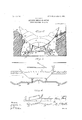
- Figure l is a perspective view of my aquatic mcrry-go-round.
- Fig. 2 is a r ont elevation of a boat with necessary features for travel along :1 track upon the bottom of the waterway.
- Fig. 3 is a side elevation of a boat traveling alongundulating rails on the bottom of the waterway.
- Fig. 4 shows a modified form of the bottom of the waterway, in'which the bottom is of undulating form and provided with friction rollers over which the boat is caused to pass.
- Fig. 5 is a fragmentary detail illustrating the application of guiding boats, as covered by my Letters Latent herein named.
- Fig. 6 illustrates a modified form of propelling the boats.
- Fig. 7 illustrates the application of my improved system to a figure eight track.
- Fig. 8 illustrates a movable track with boats secured thereto at intervals, such track and the boats thereon having an undulating or rolling motion.
- 1 is the outer cylindrical wall and 2 the inner cylindrical wall, forming an annular space in which is arranged the circular waterway 3, around which the pleasure boats 4 are to. be propelled in opposite directions, as shown in Fig. .1.
- Fig. 1 On the left of Fig. 1 are shown the guide-rails 5, 5, which are centrally arranged along the waterway 3, and
- arm 12 At the outer end of arm 12 are the downwardly extending and inwardly extending arms 13 and 14, re-
- Fig. 2 I illustrate the manner of propelling the boat 1- along two rails 18, 18, on the bottom of the waterway3, as shown on the right-hand side of Fig. l.
- 21, 21, are stiff spiral springs secured to the boat 4 and axle'l9 and Z2, 22, are loose chains connecting the boat with the outer ends of the axles.
- On the right-hand side is shown the antifriction device disengaged from the rail.
- Fig. 3 I have shown the rails 18 with rises 27 and depressions 28, to give to the boat a. pitching motion in its travel.
- Fig. 4 shows :tinodification of the 'above construction, in which the mils are replaced hy friction-rollers. 29 extending across the waterway and up and down 1 the rises and depressions.
- the power which I preiembly employ is the trolley system shown in Fig. 1, but in lieu thereof a. central shaft 30 (see Fig. 6) with radial arms 31 may be sub stituted, the outer ends of which are connected with the hosts 4 by the lines 32.
- the trip represented in Fig. l is that of the Maid of the Mist below the falls and lhe trsvel ol the heat is on a level track, as shown.
- a water-way guiding means in the water-Way, and means detachuhly connecting the boat to the guiding means, the connecting means including antifrietion rollers and a spring connection.
- a water-way arranged be tween wnlls, :i guiding means in the waiter-way, a. heat for travel in the waterway, moans detzichahly connecting the host to the guiding means and means carried by the side of the boat to contact with said wells.
- s'water-way arranged be tween walls. it guiding means in the waterway, a boat for travel in the water-way, spring; controlled means connecting the boat and the guiding means, and means carried by the sides of the host lo contact with the walls along the water-why.
- a water-Way arranged be tween we] a, guiding means in the writer-way, said guiding moans luwingnu uneven surface to rock the host ionglfw llimilly 01' its length, means detnchabiy connecting the host or the gold in means, and means carried by the boat for engagement with said walls to rock the boat from side to side, and means for propelling the boat along said guiding lllilflXJS.
Landscapes
- Cleaning In General (AREA)
Description
No. 862,157. PATENTED AUG. 6, 1907. H. HEALY.
AQUATIC MERRY-GO-ROUND. APPLIOATION FILED AUG. 3, 1906 3 SHEETS-SHEET l.
% ywcn '01,
Wit-a1 moan a 7zz/wm 77:1 yflm gym/W No. 862,157; I PATENTED AUG. 6, 1907.
H..HE-ALY.
AQUATIC MERRY-GO-ROUND.
APPLIOATION FILED AUG. 3, 1906.
3 SHEETS-SHEET 2.
scnted.
burrs HENRY H EALY, OF BUFFALO, NEW YORK.
AQUATIC MERRY-GO-ROUNED.
, Specification of Letters Patent.
Patented Aug. 6, 1907.
Application filed August 3, 1906. Serial No- 329,054.-
To all whom it may concern:
Be it known that I, HENRY IIEALY, a citizen of the United States, residing at Buffalo, in'the county of Erie and State of New York, have invented certain new and useful Improvements in Aquatic Merry-Go-Rounds; and-I do hereby declare the following to be a full, clear, and exact description of the invention, such as will enable others skilled in the art to which it appertains to make and use the same, reference being had to the accompanying drawings, and to letters or figures of reference marked thereon, which form a part of this specification.
My invention consists of an aquatic merry goqound, or in other Words a combination of novel features by means of which a pleasure trip is provided in a boat, which travels in a fixed course through a waterway, both sides of which are made to represent a particular locality.
In carrying out my invention l make use of a system of canal propulsion, for which Letters Patent No. 738,190 were granted to me on the 8th. day of September, 1903, such-system involving broadly, a waterway, a guiderail in the line of the waterway and connections on the boat for holding engagement with the guide-rail, in their travel along the saine.
The object of my invention, primarily, is to simulate a trip of The Maid of the Mist in the Niagara river, or a trip through the Rapids and Whirlpool, or any other localities of a similarly interesting or exciting character. These features are to be located at the midways of worlds fairs, or at permanent pleasure resorts, for catering to the entertainment of the public. Both the surrounding scenery and the travel upon the water are to be reproduced in a realistic manner and as nearly true to nature as is possible with artistic and mechanical means, which include running and falling water and the rolling'and tossing of the boats.
My invention therefore consists broadly of a waterway, preferably circular or endless, a series of boats for travel in such waterway, a guide-rail or rails in such waterway, either above the surface of the water or on the bottom of the waterway, for causing the boats to travel iii a fixed path, by means of arms upon the boats and in holding engagement with the guide-rail or rails, along which the arms travel, suitable power for propeL ling the boats in a direction parallel to the guide-rail or,
rails, raised sections in the bottom of the waterway, over which the boats are caused to ride in simulating the action of the tossing water of the Whirlpool Rapids and other necessary features for accurately producing the natural scenery of the locality sought to be repreln the drawings, Figure l is a perspective view of my aquatic mcrry-go-round. Fig. 2 is a r ont elevation of a boat with necessary features for travel along :1 track upon the bottom of the waterway. Fig. 3 is a side elevation of a boat traveling alongundulating rails on the bottom of the waterway. Fig. 4 shows a modified form of the bottom of the waterway, in'which the bottom is of undulating form and provided with friction rollers over which the boat is caused to pass. Fig. 5 is a fragmentary detail illustrating the application of guiding boats, as covered by my Letters Latent herein named. Fig. 6 illustrates a modified form of propelling the boats. Fig. 7 illustrates the application of my improved system to a figure eight track. Fig. 8 illustrates a movable track with boats secured thereto at intervals, such track and the boats thereon having an undulating or rolling motion. i
Referring to the drawings, 1 is the outer cylindrical wall and 2 the inner cylindrical wall, forming an annular space in which is arranged the circular waterway 3, around which the pleasure boats 4 are to. be propelled in opposite directions, as shown in Fig. .1.
On the left of Fig. 1 are shown the guide-rails 5, 5, which are centrally arranged along the waterway 3, and
upon the sides of each boat are arranged the vertically adjustable arms 6 (see Figs. 1 and 5) carrying at their outer ends the friction-wheels 7, for holding engage-,1
ment with the guide-rails 5, in their travel along the same.
In order to hold the friction-wheel 7 in engagement with the guide-rails 5, I have provided the following construction. At the outercnd of the arm 6, are the downwardly extending and inwardly extending arms 8 and 9, respectively carrying the anti-friction rollers 10 and 11, which bear against the side and under surfaces of the guide-rail 5. Hinged to the arm 6 is the horizontal arm 12, upon which is pivoted the frictionroller 7, which has bearing contact with the tread of the guiderail 5. j
At the outer end of arm 12 are the downwardly extending and inwardly extending arms 13 and 14, re-
spectively carrying the anti-friction rollers 15 and 16, I
which bear against the side and under Surfaces of the guide-rail-f). I
17 is a spring catch-arm rigid with the arm 12 and adapted for removable engagement with the arm 6,
for holding the anti-friction device on the rail 5 or for releasing the same. 1 v
In Fig. 2 I illustrate the manner of propelling the boat 1- along two rails 18, 18, on the bottom of the waterway3, as shown on the right-hand side of Fig. l.
The bottom of the boat, at each end, is provided with the axle 19, having the spring 20 interposed between it and the boat. 21, 21, are stiff spiral springs secured to the boat 4 and axle'l9 and Z2, 22, are loose chains connecting the boat with the outer ends of the axles. On the right-hand side is shown the antifriction device disengaged from the rail. On each side of the waterway, at intcrvalsfl construct the projecting obstructions 22S and 24, against which the boat strikes, to givc it a struetion 23, prevent the injurious scraping oi the boat and the'rollers 25, 26 may be made of rubber to'ense} the jar. v
In Fig. 3 I have shown the rails 18 with rises 27 and depressions 28, to give to the boat a. pitching motion in its travel.
Fig. 4 shows :tinodification of the 'above construction, in which the mils are replaced hy friction-rollers. 29 extending across the waterway and up and down 1 the rises and depressions. I
The power which I preiembly employ is the trolley system shown in Fig. 1, but in lieu thereof a. central shaft 30 (see Fig. 6) with radial arms 31 may be sub stituted, the outer ends of which are connected with the hosts 4 by the lines 32.
In'Fig. 7 .l-have shown nnnodification in which the track is in the form of o figure eight, as at 33 and in Fig. 8 I have shown another modifi ition in which the boats 4 are secured to an endless flexible track 34, which is caused to move in an undulating motion, to simulate the pitching of the waves.
The trip represented in Fig. l is that of the Maid of the Mist below the falls and lhe trsvel ol the heat is on a level track, as shown.
"If a. trip through the Rapids rind Whirlpool is to be represented, the scenery is to he correspondingly changed. The rises 27 and depressions 28 (see Fig. 3) and the obstruetions 23, 24 (see Fig. 2) are also to he i utilized, in which event the boat will pitch on the uneven mils and strike the side obstructions, thus giving the boat a pitching and rolling motion in imitation of a. trip through the Wave-tossed Rapids.
I claim.
1. In 'an amusement device, a. writer-Way, guiding means in the waterway, :1. heat for travel in the waterway, and spring controlled means detnchnbly connecting the bout to the guiding means. I I
2. In an amusement device, a water-way, guiding means in the water-Way, and means detachuhly connecting the boat to the guiding means, the connecting means including antifrietion rollers and a spring connection.
3. In. un'umnsement device. a water-way arranged be tween wnlls, :i guiding means in the waiter-way, a. heat for travel in the waterway, moans detzichahly connecting the host to the guiding means and means carried by the side of the boat to contact with said wells.
4. In an amusement device, s'water-way arranged be tween walls. it guiding means in the waterway, a boat for travel in the water-way, spring; controlled means connecting the boat and the guiding means, and means carried by the sides of the host lo contact with the walls along the water-why. w
5. in an amusement device, a water-Way arranged be tween we] a, guiding means in the writer-way, said guiding moans luwingnu uneven surface to rock the host ionglfw llimilly 01' its length, means detnchabiy connecting the host or the gold in means, and means carried by the boat for engagement with said walls to rock the boat from side to side, and means for propelling the boat along said guiding lllilflXJS.
in testimony whereof, I have signed my name to this specification, in the presence of two subscribing witnesses.
HENRY HEALY.
Witnesses:
W1 '1. Mrntnn, JOHN O. ADSIL.
Priority Applications (1)
| Application Number | Priority Date | Filing Date | Title |
|---|---|---|---|
| US32905406A US862157A (en) | 1906-08-03 | 1906-08-03 | Aquatic merry-go-round. |
Applications Claiming Priority (1)
| Application Number | Priority Date | Filing Date | Title |
|---|---|---|---|
| US32905406A US862157A (en) | 1906-08-03 | 1906-08-03 | Aquatic merry-go-round. |
Publications (1)
| Publication Number | Publication Date |
|---|---|
| US862157A true US862157A (en) | 1907-08-06 |
Family
ID=2930609
Family Applications (1)
| Application Number | Title | Priority Date | Filing Date |
|---|---|---|---|
| US32905406A Expired - Lifetime US862157A (en) | 1906-08-03 | 1906-08-03 | Aquatic merry-go-round. |
Country Status (1)
| Country | Link |
|---|---|
| US (1) | US862157A (en) |
Cited By (1)
| Publication number | Priority date | Publication date | Assignee | Title |
|---|---|---|---|---|
| US2985479A (en) * | 1958-03-10 | 1961-05-23 | Ortega Isidoro | Motor vehicle side and top stabilizing wheels |
-
1906
- 1906-08-03 US US32905406A patent/US862157A/en not_active Expired - Lifetime
Cited By (1)
| Publication number | Priority date | Publication date | Assignee | Title |
|---|---|---|---|---|
| US2985479A (en) * | 1958-03-10 | 1961-05-23 | Ortega Isidoro | Motor vehicle side and top stabilizing wheels |
Similar Documents
| Publication | Publication Date | Title |
|---|---|---|
| US808487A (en) | Pleasure-railway. | |
| US5387159A (en) | Continuous wave generating apparatus for simulated surfriding | |
| US774917A (en) | Amusement apparatus. | |
| US779464A (en) | Whirlpool for public amusement. | |
| US743968A (en) | Recreation device. | |
| US570016A (en) | Amusement apparatus | |
| US858624A (en) | Pleasure-railway. | |
| US862157A (en) | Aquatic merry-go-round. | |
| US771322A (en) | Ball-coaster. | |
| US1788798A (en) | Attraction | |
| US1546031A (en) | Aquatic amusement device | |
| US953266A (en) | Aquatic merry-go-round. | |
| US335597A (en) | Exercising-machine | |
| US1051796A (en) | Vehicle-swing. | |
| US1564952A (en) | Rotary amusement device | |
| US578354A (en) | Marine merry-go-round | |
| US888983A (en) | Pleasure-boat. | |
| US1181406A (en) | Bathing appliance. | |
| US852184A (en) | Pleasure-railway. | |
| US905282A (en) | Amusement device. | |
| US332945A (en) | Seating | |
| US422466A (en) | Pleasure-railway | |
| US542690A (en) | Pi alp to valentine d | |
| US611876A (en) | Race-track for dogs | |
| US443492A (en) | Merry-go-round |