US8619101B2 - Methods and systems for white point adjustment - Google Patents
Methods and systems for white point adjustment Download PDFInfo
- Publication number
- US8619101B2 US8619101B2 US11/810,191 US81019107A US8619101B2 US 8619101 B2 US8619101 B2 US 8619101B2 US 81019107 A US81019107 A US 81019107A US 8619101 B2 US8619101 B2 US 8619101B2
- Authority
- US
- United States
- Prior art keywords
- display
- white point
- white
- dimensional array
- points
- Prior art date
- Legal status (The legal status is an assumption and is not a legal conclusion. Google has not performed a legal analysis and makes no representation as to the accuracy of the status listed.)
- Expired - Fee Related, expires
Links
Images


Classifications
-
- G—PHYSICS
- G09—EDUCATION; CRYPTOGRAPHY; DISPLAY; ADVERTISING; SEALS
- G09G—ARRANGEMENTS OR CIRCUITS FOR CONTROL OF INDICATING DEVICES USING STATIC MEANS TO PRESENT VARIABLE INFORMATION
- G09G3/00—Control arrangements or circuits, of interest only in connection with visual indicators other than cathode-ray tubes
- G09G3/20—Control arrangements or circuits, of interest only in connection with visual indicators other than cathode-ray tubes for presentation of an assembly of a number of characters, e.g. a page, by composing the assembly by combination of individual elements arranged in a matrix no fixed position being assigned to or needed to be assigned to the individual characters or partial characters
- G09G3/2003—Display of colours
-
- G—PHYSICS
- G09—EDUCATION; CRYPTOGRAPHY; DISPLAY; ADVERTISING; SEALS
- G09G—ARRANGEMENTS OR CIRCUITS FOR CONTROL OF INDICATING DEVICES USING STATIC MEANS TO PRESENT VARIABLE INFORMATION
- G09G2320/00—Control of display operating conditions
- G09G2320/06—Adjustment of display parameters
- G09G2320/0626—Adjustment of display parameters for control of overall brightness
-
- G—PHYSICS
- G09—EDUCATION; CRYPTOGRAPHY; DISPLAY; ADVERTISING; SEALS
- G09G—ARRANGEMENTS OR CIRCUITS FOR CONTROL OF INDICATING DEVICES USING STATIC MEANS TO PRESENT VARIABLE INFORMATION
- G09G2320/00—Control of display operating conditions
- G09G2320/06—Adjustment of display parameters
- G09G2320/0666—Adjustment of display parameters for control of colour parameters, e.g. colour temperature
Definitions
- Embodiments of the present disclosure generally relate to adjusting a white point of a display device.
- Electronic devices such as computer systems or wireless cellular telephones or other data processing systems, may often include a display or display device for providing a user interface with various images, programs, menus, documents, and other types of information.
- the display may illuminate or display various colors with a color space such as the CIE XYZ color space created by the International Commission on Illumination in 1931.
- a color space such as the CIE XYZ color space created by the International Commission on Illumination in 1931.
- a specific method for associating three numbers (or tristimulus values) with each color is called a color space.
- the human eye has receptors for short, middle, and long wavelengths, also know as blue, green, and red receptors.
- the CIE XYZ color space includes a set of tristimulus values called X, Y, and Z which are also roughly red, green, and blue, respectively.
- color includes brightness and chromacity.
- the color white is a bright color while the color grey is considered to be a less bright version of that same white color.
- chromaticity of white and grey are the same while their brightness differs.
- FIG. 1 a illustrates a CIE (1931) xy chromaticity diagram with all of the chromaticities visible to the average person. These are shown in color and this region is called the gamut of human vision.
- the gamut of all visible chromaticities on the CIE plot is the tongue-shaped or horseshoe-shaped object shown in color.
- the curved edge of the gamut is called the spectral locus and corresponds to monochromatic light.
- Color temperature is a characteristic of visible light that has important applications in photography, videography, publishing and other fields.
- the color temperature of a light source is determined by comparing its hue with a theoretical, heated black-body radiator. Hue is that aspect of a color described with names such as “red”, “yellow”, etc.
- the Kelvin temperature at which the heated black-body radiator matches the hue of the light source is that source's color temperature.
- An incandescent light is very close to being a black-body radiator.
- many other light sources, such as fluorescent lamps do not emit radiation in the form of a black-body curve, and are assigned what is known as a correlated color temperature (CCT), which is the color temperature of a black body which most closely matches the lamp's perceived color.
- CCT correlated color temperature
- color temperatures include a 1850 K Candle, a 2800 K Tungsten lamp (incandescent lightbulb), a 4100 K Moonlight, a 5000 K Daylight, a 5500 K Average daylight or an electronic flash (can vary between manufacturers), a 5770 K Effective sun temperature, 6500 K Daylight, and a 9300 K TV screen (analog).
- FIG. 1 a also illustrates a black body locus, with color temperatures indicated. Wavelengths of monochromatic light are shown in blue. The lines crossing the black body locus are lines of constant correlated color temperature.
- FIG. 1 b illustrates a prior approach for matching a target white point of a display to another media.
- the prior approach includes a one dimensional correlated color temperature slider that corresponds to the black body locus illustrated in FIG. 1 a.
- the prior approach allows merely a one dimensional adjustment for a target white point. There is no way to select a target white points that is not found on the black body locus which may be referred to as the slider white point locus.
- a method includes setting the display to a first state.
- the method further includes providing a two dimensional array of white points to the display.
- the method further includes selecting a target white point from the two dimensional array of white points to visually match a desired white color of a medium.
- the method further includes encoding the selected target white point as two simultaneously captured variables.
- the method further includes deriving a second state of the display that corresponds to the target white point.
- a data processing system includes a processor coupled to a bus, a display coupled to the bus, and a memory coupled to the bus.
- the memory may be configured to store one or more programs and configured to store data for a two dimensional array of white points for presentation to the display.
- the processor is configured to receive a selection of a target white point from the two dimensional array of white points to visually match a desired white color of a medium.
- the processor may be further configured to encode the selected target white point as two simultaneously captured variables.
- the processor may be further configured to derive a second state of the display that corresponds to the target white point.
- machine readable media which contain executable instructions to cause a machine to operate as described herein, are also described.
- FIG. 1A shows a CIE xy chromaticity diagram with a black body locus.
- FIG. 1B shows a prior approach for adjusting a target white point with a one dimensional slider.
- FIG. 2 shows an example of a data processing system with a display device in accordance with at least certain embodiments of the disclosures described herein.
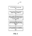
- FIG. 3 is a flow chart of an embodiment of a method of the disclosures described herein.
- FIG. 4A shows a CIE 1931 chromaticity diagram that is transformed to provide a two dimensional array of white points in accordance with one embodiment of the disclosures described herein.
- FIG. 4B shows a display providing a view of the two dimensional array of white points in accordance with one embodiment of the disclosures described herein.
- FIG. 5 is a flow chart of an embodiment of a method of setting a target white point of a display for the disclosures described herein.
- FIGS. 6A-6C show a display providing a view of a chromaticity diagram in accordance with some embodiments of the disclosures described herein.
- FIG. 6D shows a chromaticity diagram that is part of a CIE chromaticity diagram with xy derived coordinates.
- the present disclosure can relate to an apparatus for performing one or more of the operations described herein.
- This apparatus may be specially constructed for the required purposes, or it may comprise a general purpose computer selectively activated or reconfigured by a computer program stored in the computer.
- a computer program may include instructions for performing the operations described herein and may be stored in a machine (e.g.
- ROMs read-only memories
- RAMs random access memories
- EPROMs erasable programmable ROMs
- EEPROMs electrically erasable programmable ROMs
- magnetic or optical cards or any type of media suitable for storing electronic instructions, and each coupled to a bus.
- a machine-readable medium includes any mechanism for storing or transmitting information in a form readable by a machine (e.g., a computer).
- a machine-readable medium includes read only memory (“ROM”); random access memory (“RAM”); magnetic disk storage media; optical storage media; flash memory devices; electrical, optical, acoustical or other form of propagated signals (e.g., carrier waves, infrared signals, digital signals, etc.); etc.
- FIG. 2 shows an example of a data processing system with a display device in accordance with at least certain embodiments of the disclosures described herein.
- FIG. 2 shows one example of a typical computer system which may be used with the present disclosure. Note that while FIG. 2 illustrates various components of a computer system, it is not intended to represent any particular architecture or manner of interconnecting the components as such details are not germane to the present disclosure.
- PDAs personal digital assistants
- handheld computers cellular telephones
- media players e.g., an iPod
- devices which combine aspects or functions of these devices (e.g., a media player combined with a PDS and a cellular telephone in one device), an embedded processing device within another device, network computers and other data processing systems which have fewer components or perhaps more components may also be used to implement one or more embodiments of the present disclosure.
- the computer system of FIG. 2 may, for example, be an Apple Macintosh computer.
- the computer system 101 which is a form of a data processing system, includes a bus 102 which is coupled to a microprocessor 103 and a ROM 107 and volatile RAM 105 and a non-volatile memory 106 .
- the microprocessor 103 which may be, for example, a microprocessor from Intel or a G3 or G4 microprocessor from Motorola, Inc. or IBM is coupled to cache memory 104 as shown in the example of FIG. 2 .
- the bus 102 interconnects these various components together and also interconnects these components 103 , 107 , 105 , and 106 to a display controller and display device(s) 108 , which may include display devices and corresponding frame buffers, and to peripheral devices such as input/output (I/O) devices which may be mice, keyboards, modems, network interfaces, printers, scanners, video cameras and other devices which are well known in the art.
- the display controller 108 may include one or more frame buffers which are used to refresh multiple display devices or the frame buffers may be in a system RAM (e.g., RAM 105 ).
- the input/output devices 110 are coupled to the system through input/output controllers 109 .
- the volatile RAM 105 is typically implemented as dynamic RAM (DRAM) which requires power continually in order to refresh or maintain the data in the memory.
- the non-volatile memory 106 is typically a magnetic hard drive or a magnetic optical drive or an optical drive or a DVD RAM or other type of memory systems which maintain data even after power is removed from the system.
- the non-volatile memory will also be a random access memory although this is not required. While FIG. 2 shows that the non-volatile memory is a local device coupled directly to the rest of the components in the data processing system, it will be appreciated that the present disclosure may utilize a non-volatile memory which is remote from the system, such as a network storage device which is coupled to the data processing system through a network interface such as a modem or Ethernet interface.
- the bus 102 may include one or more buses connected to each other through various bridges, controllers and/or adapters as is well known in the art.
- the I/O controller 109 includes a USB (Universal Serial Bus) adapter for controlling USB peripherals, and/or an IEEE-1394 bus adapter for controlling IEEE-1394 peripherals.
- USB Universal Serial Bus
- aspects of the present disclosure may be embodied, at least in part, in software. That is, the techniques may be carried out in a computer system or other data processing system in response to its processor, such as a microprocessor, executing sequences of instructions contained in a memory, such as ROM 107 , volatile RAM 105 , non-volatile memory 106 , cache 104 or a remote storage device.
- a processor such as a microprocessor
- a memory such as ROM 107 , volatile RAM 105 , non-volatile memory 106 , cache 104 or a remote storage device.
- hardwired circuitry may be used in combination with software instructions to implement the present disclosure.
- the techniques are not limited to any specific combination of hardware circuitry and software nor to any particular source for the instructions executed by the data processing system.
- various functions and operations are described as being performed by or caused by software code to simplify description. However, those skilled in the art will recognize what is meant by such expressions is that the functions result from execution of the code by a processor,
- At least one embodiment of the present disclosure seeks to describe a data processing system 101 that includes a microprocessor or processor 103 coupled to a bus 102 .
- the data processing system 101 further includes a display or display device 108 coupled to the bus 102 .
- a memory block such as ROM 107 , RAM 105 , or nonvolatile memory 106 is coupled to the bus 102 with the memory block being configured to store one or more programs and configured to store data for a two dimensional array of white points for presentation to the display 108 .
- the processor 103 is configured to receive a selection of a target white point from the two dimensional array of white points to visually match a desired white color of a medium.
- a user of the data processing system 101 may desire to match a white point of the display 108 to a white point of a medium. The user then selects the target white point from two dimensional array of white points in order to visually match the desired white color of the medium.
- the processor is configured to encode the selected target white point as two simultaneously captured variables.
- the processor is further configured to provide a first state of the display and then derive a second state of the display that corresponds to the target white point.
- the data processing system which is an electronic device includes a processor 103 coupled to a bus 102 and a display 108 coupled to the bus 102 .
- the processor 103 is configured to provide a two dimensional array of white points for presentation to the display and to receive a selection of a marker of a white point from the two dimensional array of white points to visually match a desired white color of a medium.
- the processor 103 is further configured to set a native white point for the display.
- the processor 103 is further configured to convert coordinates of the two dimensional array into chromaticity coordinates of a chromaticity diagram.
- the processor 103 is further configured to convert the chromaticity coordinates into red, green, and blue (RGB) values.
- RGB red, green, and blue
- the processor 103 is further configured to determine if a certain value of a luminance is desired for the display.
- the processor 103 is further configured to adjust the RGB values until at least one RGB value reaches the maximum values of the display if no certain value of the luminance is desired for the display.
- FIG. 3 is a flow chart of an embodiment of a method of adjusting a target white point of a display for the disclosures described herein.
- the method 300 for adjusting the white point of the display includes setting the display to a first state at block 302 . Setting the display to the first state may occur by encoding a display profile or by creating a set of parameters for the display.
- the method 300 further includes providing a two dimensional array of white points to the display at block 304 .
- the method 300 further includes selecting a target white point from the two dimensional array of white points to visually match a desired white color of a medium at block 306 .
- the method 300 further includes encoding the selected target white point as two simultaneously captured variables at block 308 .
- the method 300 further includes deriving a second state of the display that corresponds to the target white point at block 310 .
- providing the two dimensional array of white points to the display is based on a portion of the first state.
- the two dimensional array of white points may further include relative white point values in a predetermined array in a form of an image of different shades of white points that are relative to white point values of the portion of the first state.
- the white point array contains white points of different hues, like a color picker, allowing a relative selection of the white points. The selection of the white point may occur based on desiring a more reddish or more pinkish than current white point in order to match the desired white point.
- the complete first state of the display is not required. Only the partial state of the display that determines the code of the white points of the display is required.
- providing the two dimensional array of white points to the display is dynamically generated based on the first state.
- the two dimensional array of white points may further include absolute white point values based on the first state.
- a point marked as D50 in the array corresponds to exactly the D50 standard.
- the first state of the display at block 302 is critical for building the white point array.
- providing the two dimensional array of white points to the display is based on a predetermined image that is dynamically altered dependent on the first state of the display.
- deriving the second state of the display that corresponds to the target white point is based on the two captured variables of the target white point and at least a portion of the first state.
- the white point array may contain white points of different hues allowing a relative selection of the white points. Deriving the second state of the display depends only on a portion of the first state that determines the code of the white points of the display.
- the method 300 may further include deriving an optimum gray tracking of the display based on deriving the second state of the display that corresponds to the target white point of the display.
- Gray tracking indicates the degree of closeness of the chromaticity of grays generated from various levels of equal red, green, and blue input signals to the chromaticity of a target, for example the white point of the display.
- the method 300 may further include converting the two variables into chromaticity coordinates such as CIE xy, CIE Lu′v′, or CIE La*b* that will be discussed in FIGS. 4-7 .
- FIG. 4A shows a CIE 1931 chromaticity diagram that is transformed to provide a two dimensional array of white points in accordance with one embodiment of the disclosures described herein.
- the chromaticity diagram 400 includes x and y chromaticity coordinates derived from the tristimulus values X, Y, and Z, a color gamut 450 , a black body locus or white point locus 460 , and a transformation region 470 that corresponds to a two dimensional array of white points 402 in FIG. 4B which shows a display providing a view of the two dimensional array of white points 402 with an adjustable target white point in accordance with one embodiment of the disclosures described herein.
- the display may provide the view based on a display calibration program.
- the X and Y coordinates may be presented to the display or represented as tint (vertical axis) and correlated color temperature (horizontal axis) parameters as shown in FIG. 4B .
- the two dimensional array of white points 402 includes a marker 404 and an optional correlated color temperature (CCT) slider 410 with a slider bar 416 .
- the slider 410 includes various correlated color temperatures such as 412 , 414 , 418 , and 420 .
- 412 , 414 , 418 , and 420 correspond to 9300K, standard D65, standard D50, and 4500K, respectively.
- the slider 410 may not be necessary.
- the slider 410 can be updated dynamically and thus serve as a scale for the two dimensional adjustment of the target white point to the equivalent temperature/tint numerical (slider) adjustments.
- a white patch area 430 displays the same white point selected by the marker 404 .
- a user can select a desired white point setting for a display. Changing the white point adjusts the overall color tint of the display. Typically, a user will want to set the white point to the display's native white point or a standard white point such as D50 or D65.
- a temperature slider 410 and a tint slider are explicitly provided to the two dimensional array of white points 402 .
- the temperature slider 410 and the tint slider are not explicitly provided to the two dimensional array of white points 402 .
- the dimensions of the array 402 in the form of a rectangle or other shape are temperature and tint though.
- the interior of the rectangle can be colored with the allowed target whites and the user can select by clicking or dragging in the rectangle.
- the user simultaneously adjusts the temperature and tint of the target white point of the display.
- the visualization within the rectangle or other shape of the target white colors may help the user to navigate quicker than with two explicit temperature and tint sliders adjusting sequentially toward the desired target white point.
- the previous rectangle can be morphed into a circular sector region around the black body locus in the chromaticity diagram which allows two dimensional control of the selection of the target white point.
- a more experienced user such as a professional who is more familiar with the black body locus can navigate easier in a virtual chromaticity diagram toward the desired white point.
- FIG. 5 is a flow chart of an embodiment of a method of setting a target white point of a display for the disclosures described herein.
- the method 500 for setting the white point of the display includes providing a two dimensional array of white points to the display based on a current white point setting of the display at block 502 .
- a marker which may be in the form of various shapes, marks a position of a current white point on the two dimensional array.
- the method 500 further includes setting a native white point for the display at block 504 .
- a prior approach would set the maximum values of the video card tables to [1,1,1] which represents a maximum intensity for the display. This ensures that the display native white point is set.
- the method 500 further includes a user selecting a new position of the marker of the white point in the two dimensional array of white points in order to visually match a white point of another medium at block 506 .
- the user makes the selection with an input device.
- the two dimensional array of white points 402 is part of the CIE chromaticity diagram 400 as discussed above, the placement of the white points in the two dimensional array 402 is familiar to those knowing the CIE 1931 chromaticity diagram 400 .
- the method 500 further includes converting coordinates of the two dimensional array into xy chromaticity coordinates of the chromaticity diagram at block 508 using the inverse of equations (1) and (2) discussed above.
- the method 500 further includes computing RGB values corresponding to xy and a maximum luminance, Y max , of the display for chromaticities xy at block 510 .
- Y value which represents a measure of the brightness or luminance of a color
- a fraction of the maximum value of Y may be used. For example, if the range of Y is [0,1], the value for Y is 0.3 for one embodiment.
- a color model is selected.
- the color model may be a matrix based model (linear device).
- Y is set to an arbitrary value (i.e., 1).
- the coordinates xyY are converted to RGB (i.e., xyY to XYZ and XYZ to RGB).
- RGB values are then scaled up and/or down to R′G′B′ until maximum values of R′G′B′ equal maximum display device values.
- R′G′B′ is then converted to X′Y′Z′.
- Y′ is the maximum luminance Y max of the display for xy chromaticity coordinates.
- a color model is selected.
- the color model may be a three dimensional (3D) look up table (LUT) based model for an arbitrary display device.
- the 3D LUT device response values are measured.
- xyY outputs are measured for all combinations into a 3D LUT table.
- xyY values are interpolated in the 3D LUT based model. The Y value for which at least one of the RGB values reaches a value larger than 1 is Y max .
- the method 500 further includes determining if a certain value of the luminance, Y t , is desired for the display after matching the white point of the display to the white point of another medium at block 512 . If the certain value of the luminance, Y t , exceeds the Y max value at block 514 , then a color patch is provided with RGB colors at block 516 . At block 514 , the luminance level can not be reached and only the white point can be adjusted with the color patch. If further adjustment of the desired white point is needed at block 518 , the method 500 returns to block 506 . If the user is satisfied with the white point at block 518 , then the method 500 terminates at block 520 with the luminance Y t not being reached.
- the method 500 further includes computing RGB values corresponding to xy and luminance Y t at block 522 .
- a color model is selected.
- the color model may be a matrix based model (linear device).
- Y is set to the luminance Y t value.
- the coordinates xyY are converted to RGB (i.e., xyY to XYZ and XYZ to RGB).
- the method 500 further includes providing a color patch with RBG colors at block 524 .
- the method 500 further includes determining whether the desired white point can be achieved from the color patch at block 526 . If a user is satisfied with the white point, then the RGB values are used to set the white point of the display at block 528 . Otherwise, if further adjustment of the desired white point is needed at block 526 , the method 500 returns to the block 506 .
- FIGS. 6A-6C show a display providing a view of a chromaticity diagram with an adjustable target white point in accordance with some embodiments of the disclosures described herein.
- FIG. 6A shows a chromaticity diagram 600 that is part of a CIE 1931 chromaticity diagram with xy derived coordinates.
- the diagram 600 includes a target white point 602 equal to xy:[0.3628, 0.3723] with a correlated color temperature of 4428K.
- Various correlated color temperatures points are labeled on or near a white point locus 610 .
- FIG. 6B shows a chromaticity diagram 620 that is part of a CIE 1931 chromaticity diagram with xy derived coordinates.
- the diagram 620 includes a target white point 622 equal to xy:[0.3210, 0.3505] with a correlated color temperature of 6992K.
- Various correlated color temperatures points are labeled on or near a white point locus 630 .
- FIG. 6C shows a chromaticity diagram 640 that is part of a CIE 1931 chromaticity diagram with xy derived coordinates.
- the diagram 640 includes a target white point 642 equal to xy:[0.3177, 0.3521] with a correlated color temperature of 6128K.
- Various correlated color temperatures points are labeled on or near a white point locus 650 .
- FIG. 6D shows a chromaticity diagram 660 that is part of a CIE 1931 chromaticity diagram with xy derived coordinates.
- the diagram 660 includes a target white point 662 equal to xy:[0.2678, 0.2942] with a correlated color temperature of 11109K.
- Various correlated color temperatures points are labeled on or near a white point locus 670 .
- the systems and methods of the present disclosure enable numerous advantages for adjusting a white point of a display compared to prior approaches.
- the two dimensional array of white points provided to a display enables selection of a white point that is not located on the black body locus or white point locus.
- the target white points 602 , 622 , 642 , and 662 are not located on their respective white body locus curves. A prior approach would not be able to select such a target white point.
- the systems and methods described improve a visual display calibrator by allowing a user to select a target white point based on visual matching in addition to the adjustments provided by a correlated color temperature slider.
- the new adjustment allows two degrees of freedom and produces a better user experience when selecting the target white point of the display to match a white point of another medium.
- the white point of the display results in a closer match to the target white point or intended white point of a particular media.
- the user experiences a better and more predictable behavior of the calibration process and of the color performance of the display.
- the final adjustment of the target white point of the display is more flexible and precise. Overall, the user experience with the display calibrator is improved.
Landscapes
- Engineering & Computer Science (AREA)
- Physics & Mathematics (AREA)
- Computer Hardware Design (AREA)
- General Physics & Mathematics (AREA)
- Theoretical Computer Science (AREA)
- Processing Of Color Television Signals (AREA)
Abstract
Description
drawX=W*(CIEx−CIEx0)/(CIEx1−CIEx0) (1)
drawY=H*(CIEy−CIEy0)/(CIEy1−CIEy0) (2)
Claims (46)
Priority Applications (1)
| Application Number | Priority Date | Filing Date | Title |
|---|---|---|---|
| US11/810,191 US8619101B2 (en) | 2007-06-04 | 2007-06-04 | Methods and systems for white point adjustment |
Applications Claiming Priority (1)
| Application Number | Priority Date | Filing Date | Title |
|---|---|---|---|
| US11/810,191 US8619101B2 (en) | 2007-06-04 | 2007-06-04 | Methods and systems for white point adjustment |
Publications (2)
| Publication Number | Publication Date |
|---|---|
| US20080297456A1 US20080297456A1 (en) | 2008-12-04 |
| US8619101B2 true US8619101B2 (en) | 2013-12-31 |
Family
ID=40087575
Family Applications (1)
| Application Number | Title | Priority Date | Filing Date |
|---|---|---|---|
| US11/810,191 Expired - Fee Related US8619101B2 (en) | 2007-06-04 | 2007-06-04 | Methods and systems for white point adjustment |
Country Status (1)
| Country | Link |
|---|---|
| US (1) | US8619101B2 (en) |
Cited By (2)
| Publication number | Priority date | Publication date | Assignee | Title |
|---|---|---|---|---|
| US10264231B2 (en) | 2017-03-31 | 2019-04-16 | The Directv Group, Inc. | Dynamically scaling the color temperature and luminance of a display output |
| US20230418062A1 (en) * | 2022-06-23 | 2023-12-28 | Snap Inc. | Color calibration tool for see-through augmented reality environment |
Families Citing this family (10)
| Publication number | Priority date | Publication date | Assignee | Title |
|---|---|---|---|---|
| JP5268538B2 (en) * | 2008-10-02 | 2013-08-21 | 三菱電機株式会社 | Display device color adjustment system |
| JP4623137B2 (en) * | 2008-05-14 | 2011-02-02 | 富士ゼロックス株式会社 | Color processing apparatus, method and program |
| US8195054B2 (en) * | 2008-11-26 | 2012-06-05 | Samsung Electronics Co., Ltd | Apparatus and method for transmitting and receiving an information symbol in a visible light communication system for color code modulation |
| JP5714858B2 (en) * | 2010-09-30 | 2015-05-07 | 株式会社ジャパンディスプレイ | Method for adjusting chromaticity of display device |
| KR101803571B1 (en) * | 2011-06-17 | 2017-11-30 | 엘지디스플레이 주식회사 | Stereoscopic Image Display Device and Driving Method thereof |
| KR20160031466A (en) * | 2013-07-14 | 2016-03-22 | 엘지전자 주식회사 | Method and apparatus for transmitting and receiving ultra high-definition broadcasting signal for expressing high-quality color in digital broadcasting system |
| US20150310794A1 (en) * | 2014-04-23 | 2015-10-29 | Qualcomm Incorporated | Graphical elements for white-point calibration and adjustment techniques for displays |
| US10170080B2 (en) * | 2016-09-06 | 2019-01-01 | Apple Inc. | Electronic device having ancillary display with color control |
| CN111402817B (en) * | 2020-03-30 | 2021-05-14 | 合肥京东方光电科技有限公司 | White point coordinate compensation method and device, computer equipment and storage medium |
| CN115985267B (en) * | 2022-12-08 | 2025-08-08 | 北京奕斯伟计算技术股份有限公司 | White point brightness correction method, device, electronic device and storage medium |
Citations (18)
| Publication number | Priority date | Publication date | Assignee | Title |
|---|---|---|---|---|
| USH1506H (en) * | 1991-12-11 | 1995-12-05 | Xerox Corporation | Graphical user interface for editing a palette of colors |
| US5483259A (en) * | 1994-04-12 | 1996-01-09 | Digital Light & Color Inc. | Color calibration of display devices |
| US5570108A (en) * | 1994-06-27 | 1996-10-29 | Radius Inc. | Method and apparatus for display calibration and control |
| US6377702B1 (en) * | 1999-12-08 | 2002-04-23 | Sony Corporation | Color cast detection and removal in digital images |
| US20020158885A1 (en) * | 2001-04-12 | 2002-10-31 | Brokenshire Daniel Alan | Method and apparatus for generating gammacorrected antialiased lines |
| US20030193565A1 (en) * | 2002-04-10 | 2003-10-16 | Senfar Wen | Method and apparatus for visually measuring the chromatic characteristics of a display |
| US6686953B1 (en) * | 2000-03-01 | 2004-02-03 | Joseph Holmes | Visual calibration target set method |
| US20040165094A1 (en) * | 2002-11-26 | 2004-08-26 | Canon Kabushiki Kaisha | Image pickup apparatus and method, recording medium, and program providing user selected hue and white balance settings |
| US6809714B1 (en) * | 1999-08-30 | 2004-10-26 | International Business Machines Corporation | Color image processing method, color image processing apparatus, and liquid-crystal display |
| US20050008258A1 (en) * | 1999-05-06 | 2005-01-13 | Hiroaki Suzuki | Method, computer readable medium and apparatus for converting color image resolution |
| US6862012B1 (en) * | 1999-10-18 | 2005-03-01 | International Business Machines Corporation | White point adjusting method, color image processing method, white point adjusting apparatus and liquid crystal display device |
| US20060221093A1 (en) * | 2000-04-11 | 2006-10-05 | Holub Richard A | Methods and apparatus for calibrating a color display |
| US20070065006A1 (en) * | 2005-09-22 | 2007-03-22 | Adobe Systems Incorporated | Color correction based on skin color |
| US20070081102A1 (en) * | 2005-10-11 | 2007-04-12 | Texas Instruments Incorporated | Apparatus and method for automatically adjusting white point during video display |
| US20080030518A1 (en) * | 2004-04-09 | 2008-02-07 | Clairvoyante, Inc | Systems and Methods for Selecting a White Point for Image Displays |
| US20080266316A1 (en) * | 2007-04-26 | 2008-10-30 | Canon Kabushiki Kaisha | Color processing apparatus and method thereof |
| US20090051711A1 (en) * | 2000-12-08 | 2009-02-26 | Silicon Graphics, Inc. | Compact Flat Panel Color Calibration System |
| US20090128867A1 (en) * | 2001-12-31 | 2009-05-21 | Edge Christopher J | Calibration techniques for imaging devices |
-
2007
- 2007-06-04 US US11/810,191 patent/US8619101B2/en not_active Expired - Fee Related
Patent Citations (18)
| Publication number | Priority date | Publication date | Assignee | Title |
|---|---|---|---|---|
| USH1506H (en) * | 1991-12-11 | 1995-12-05 | Xerox Corporation | Graphical user interface for editing a palette of colors |
| US5483259A (en) * | 1994-04-12 | 1996-01-09 | Digital Light & Color Inc. | Color calibration of display devices |
| US5570108A (en) * | 1994-06-27 | 1996-10-29 | Radius Inc. | Method and apparatus for display calibration and control |
| US20050008258A1 (en) * | 1999-05-06 | 2005-01-13 | Hiroaki Suzuki | Method, computer readable medium and apparatus for converting color image resolution |
| US6809714B1 (en) * | 1999-08-30 | 2004-10-26 | International Business Machines Corporation | Color image processing method, color image processing apparatus, and liquid-crystal display |
| US6862012B1 (en) * | 1999-10-18 | 2005-03-01 | International Business Machines Corporation | White point adjusting method, color image processing method, white point adjusting apparatus and liquid crystal display device |
| US6377702B1 (en) * | 1999-12-08 | 2002-04-23 | Sony Corporation | Color cast detection and removal in digital images |
| US6686953B1 (en) * | 2000-03-01 | 2004-02-03 | Joseph Holmes | Visual calibration target set method |
| US20060221093A1 (en) * | 2000-04-11 | 2006-10-05 | Holub Richard A | Methods and apparatus for calibrating a color display |
| US20090051711A1 (en) * | 2000-12-08 | 2009-02-26 | Silicon Graphics, Inc. | Compact Flat Panel Color Calibration System |
| US20020158885A1 (en) * | 2001-04-12 | 2002-10-31 | Brokenshire Daniel Alan | Method and apparatus for generating gammacorrected antialiased lines |
| US20090128867A1 (en) * | 2001-12-31 | 2009-05-21 | Edge Christopher J | Calibration techniques for imaging devices |
| US20030193565A1 (en) * | 2002-04-10 | 2003-10-16 | Senfar Wen | Method and apparatus for visually measuring the chromatic characteristics of a display |
| US20040165094A1 (en) * | 2002-11-26 | 2004-08-26 | Canon Kabushiki Kaisha | Image pickup apparatus and method, recording medium, and program providing user selected hue and white balance settings |
| US20080030518A1 (en) * | 2004-04-09 | 2008-02-07 | Clairvoyante, Inc | Systems and Methods for Selecting a White Point for Image Displays |
| US20070065006A1 (en) * | 2005-09-22 | 2007-03-22 | Adobe Systems Incorporated | Color correction based on skin color |
| US20070081102A1 (en) * | 2005-10-11 | 2007-04-12 | Texas Instruments Incorporated | Apparatus and method for automatically adjusting white point during video display |
| US20080266316A1 (en) * | 2007-04-26 | 2008-10-30 | Canon Kabushiki Kaisha | Color processing apparatus and method thereof |
Non-Patent Citations (5)
| Title |
|---|
| International Color Consortium, Specification ICC.1:2004-10, www.color.org, Oct. 2004, 112 pages. |
| Technical Note TN2035: ColorSync on Mac OS X, http://developer.aple.com/technotes/tn/tn2035.html, Mar. 19, 2007, 47 pages. |
| Wikipedia, CIE 1931 color space, http//en.wikipedia.org/w/index.php?title=CIE-1931 color-space&oldid=115984057, Mar. 18, 2007, 9 pages. |
| Wikipedia, Color Temperature, http://en.wikipedia.org/wiki/Color-Temperature, May 15, 2007, 7 pages. |
| William B. Cowan, "An Inexpensive Scheme for Calibration of a Colour Monitor in Terms of CIE Standard Coordinates", Jul. 1963, Computer Graphics, vol. 17, No. 3, pp. 315-321. * |
Cited By (3)
| Publication number | Priority date | Publication date | Assignee | Title |
|---|---|---|---|---|
| US10264231B2 (en) | 2017-03-31 | 2019-04-16 | The Directv Group, Inc. | Dynamically scaling the color temperature and luminance of a display output |
| US20230418062A1 (en) * | 2022-06-23 | 2023-12-28 | Snap Inc. | Color calibration tool for see-through augmented reality environment |
| US12332438B2 (en) * | 2022-06-23 | 2025-06-17 | Snap Inc. | Color calibration tool for see-through augmented reality environment |
Also Published As
| Publication number | Publication date |
|---|---|
| US20080297456A1 (en) | 2008-12-04 |
Similar Documents
| Publication | Publication Date | Title |
|---|---|---|
| US8619101B2 (en) | Methods and systems for white point adjustment | |
| JP3634633B2 (en) | Image processing apparatus and method | |
| US10217438B2 (en) | User interface and method for directly setting display white point | |
| US20100097407A1 (en) | Color generation change using multiple illuminant types | |
| US20130335439A1 (en) | System and method for converting color gamut | |
| JP5897159B2 (en) | Display device and control method thereof | |
| CN103004213A (en) | Tone and gamut mapping methods and apparatus | |
| JP2005354711A (en) | Color gamut mapping apparatus and method using vector stretching | |
| WO2015164507A1 (en) | Graphical elements for white-point calibration and adjustment techniques for displays | |
| US8866838B2 (en) | Color management for multiple display presentation of visual media | |
| CN102696069B (en) | Electronic device | |
| MX2011002044A (en) | Image display apparatus. | |
| CN107784993A (en) | A kind of gamut compression method, apparatus and display device | |
| JP4592090B2 (en) | Color processing method and apparatus | |
| US20090268961A1 (en) | Color-saturation control method | |
| US8564860B2 (en) | Image processor for correcting image data | |
| US8416455B2 (en) | Image processor for correcting image data | |
| CN115720727A (en) | Control design for perceptually uniform color adjustment | |
| US11076461B2 (en) | User control modality for LED color tuning | |
| CN110709895B (en) | Apparatus and method for dynamic white point compensation to improve perceived color of synthesized content | |
| JP3805247B2 (en) | Image processing apparatus and method | |
| US8189909B2 (en) | Color temperature conversion method and apparatus having luminance correction conversion function | |
| JP6137867B2 (en) | Display device and control method thereof | |
| US8310502B2 (en) | System and method for adjusting display input values | |
| WO2020236525A1 (en) | User control modality for led color tuning |
Legal Events
| Date | Code | Title | Description |
|---|---|---|---|
| AS | Assignment |
Owner name: APPLE INC., CALIFORNIA Free format text: ASSIGNMENT OF ASSIGNORS INTEREST;ASSIGNORS:MARCU, GABRIEL G.;SWEN, STEVE;REEL/FRAME:019438/0445 Effective date: 20070601 |
|
| FEPP | Fee payment procedure |
Free format text: PAYOR NUMBER ASSIGNED (ORIGINAL EVENT CODE: ASPN); ENTITY STATUS OF PATENT OWNER: LARGE ENTITY Free format text: PAYER NUMBER DE-ASSIGNED (ORIGINAL EVENT CODE: RMPN); ENTITY STATUS OF PATENT OWNER: LARGE ENTITY |
|
| STCF | Information on status: patent grant |
Free format text: PATENTED CASE |
|
| FPAY | Fee payment |
Year of fee payment: 4 |
|
| MAFP | Maintenance fee payment |
Free format text: PAYMENT OF MAINTENANCE FEE, 8TH YEAR, LARGE ENTITY (ORIGINAL EVENT CODE: M1552); ENTITY STATUS OF PATENT OWNER: LARGE ENTITY Year of fee payment: 8 |
|
| FEPP | Fee payment procedure |
Free format text: MAINTENANCE FEE REMINDER MAILED (ORIGINAL EVENT CODE: REM.); ENTITY STATUS OF PATENT OWNER: LARGE ENTITY |
|
| LAPS | Lapse for failure to pay maintenance fees |
Free format text: PATENT EXPIRED FOR FAILURE TO PAY MAINTENANCE FEES (ORIGINAL EVENT CODE: EXP.); ENTITY STATUS OF PATENT OWNER: LARGE ENTITY |
|
| STCH | Information on status: patent discontinuation |
Free format text: PATENT EXPIRED DUE TO NONPAYMENT OF MAINTENANCE FEES UNDER 37 CFR 1.362 |