US8610390B2 - Method and apparatus for controlling torque of an electric motor driven vehicle - Google Patents
Method and apparatus for controlling torque of an electric motor driven vehicle Download PDFInfo
- Publication number
- US8610390B2 US8610390B2 US13/297,585 US201113297585A US8610390B2 US 8610390 B2 US8610390 B2 US 8610390B2 US 201113297585 A US201113297585 A US 201113297585A US 8610390 B2 US8610390 B2 US 8610390B2
- Authority
- US
- United States
- Prior art keywords
- torque
- limit
- boundary
- speed
- drive
- Prior art date
- Legal status (The legal status is an assumption and is not a legal conclusion. Google has not performed a legal analysis and makes no representation as to the accuracy of the status listed.)
- Active, expires
Links
Images


Classifications
-
- B—PERFORMING OPERATIONS; TRANSPORTING
- B60—VEHICLES IN GENERAL
- B60L—PROPULSION OF ELECTRICALLY-PROPELLED VEHICLES; SUPPLYING ELECTRIC POWER FOR AUXILIARY EQUIPMENT OF ELECTRICALLY-PROPELLED VEHICLES; ELECTRODYNAMIC BRAKE SYSTEMS FOR VEHICLES IN GENERAL; MAGNETIC SUSPENSION OR LEVITATION FOR VEHICLES; MONITORING OPERATING VARIABLES OF ELECTRICALLY-PROPELLED VEHICLES; ELECTRIC SAFETY DEVICES FOR ELECTRICALLY-PROPELLED VEHICLES
- B60L15/00—Methods, circuits, or devices for controlling the traction-motor speed of electrically-propelled vehicles
- B60L15/20—Methods, circuits, or devices for controlling the traction-motor speed of electrically-propelled vehicles for control of the vehicle or its driving motor to achieve a desired performance, e.g. speed, torque, programmed variation of speed
-
- B—PERFORMING OPERATIONS; TRANSPORTING
- B60—VEHICLES IN GENERAL
- B60W—CONJOINT CONTROL OF VEHICLE SUB-UNITS OF DIFFERENT TYPE OR DIFFERENT FUNCTION; CONTROL SYSTEMS SPECIALLY ADAPTED FOR HYBRID VEHICLES; ROAD VEHICLE DRIVE CONTROL SYSTEMS FOR PURPOSES NOT RELATED TO THE CONTROL OF A PARTICULAR SUB-UNIT
- B60W10/00—Conjoint control of vehicle sub-units of different type or different function
- B60W10/04—Conjoint control of vehicle sub-units of different type or different function including control of propulsion units
- B60W10/08—Conjoint control of vehicle sub-units of different type or different function including control of propulsion units including control of electric propulsion units, e.g. motors or generators
-
- B—PERFORMING OPERATIONS; TRANSPORTING
- B60—VEHICLES IN GENERAL
- B60W—CONJOINT CONTROL OF VEHICLE SUB-UNITS OF DIFFERENT TYPE OR DIFFERENT FUNCTION; CONTROL SYSTEMS SPECIALLY ADAPTED FOR HYBRID VEHICLES; ROAD VEHICLE DRIVE CONTROL SYSTEMS FOR PURPOSES NOT RELATED TO THE CONTROL OF A PARTICULAR SUB-UNIT
- B60W20/00—Control systems specially adapted for hybrid vehicles
-
- B—PERFORMING OPERATIONS; TRANSPORTING
- B60—VEHICLES IN GENERAL
- B60L—PROPULSION OF ELECTRICALLY-PROPELLED VEHICLES; SUPPLYING ELECTRIC POWER FOR AUXILIARY EQUIPMENT OF ELECTRICALLY-PROPELLED VEHICLES; ELECTRODYNAMIC BRAKE SYSTEMS FOR VEHICLES IN GENERAL; MAGNETIC SUSPENSION OR LEVITATION FOR VEHICLES; MONITORING OPERATING VARIABLES OF ELECTRICALLY-PROPELLED VEHICLES; ELECTRIC SAFETY DEVICES FOR ELECTRICALLY-PROPELLED VEHICLES
- B60L2240/00—Control parameters of input or output; Target parameters
- B60L2240/40—Drive Train control parameters
- B60L2240/42—Drive Train control parameters related to electric machines
- B60L2240/421—Speed
-
- B—PERFORMING OPERATIONS; TRANSPORTING
- B60—VEHICLES IN GENERAL
- B60L—PROPULSION OF ELECTRICALLY-PROPELLED VEHICLES; SUPPLYING ELECTRIC POWER FOR AUXILIARY EQUIPMENT OF ELECTRICALLY-PROPELLED VEHICLES; ELECTRODYNAMIC BRAKE SYSTEMS FOR VEHICLES IN GENERAL; MAGNETIC SUSPENSION OR LEVITATION FOR VEHICLES; MONITORING OPERATING VARIABLES OF ELECTRICALLY-PROPELLED VEHICLES; ELECTRIC SAFETY DEVICES FOR ELECTRICALLY-PROPELLED VEHICLES
- B60L2240/00—Control parameters of input or output; Target parameters
- B60L2240/40—Drive Train control parameters
- B60L2240/42—Drive Train control parameters related to electric machines
- B60L2240/423—Torque
-
- B—PERFORMING OPERATIONS; TRANSPORTING
- B60—VEHICLES IN GENERAL
- B60W—CONJOINT CONTROL OF VEHICLE SUB-UNITS OF DIFFERENT TYPE OR DIFFERENT FUNCTION; CONTROL SYSTEMS SPECIALLY ADAPTED FOR HYBRID VEHICLES; ROAD VEHICLE DRIVE CONTROL SYSTEMS FOR PURPOSES NOT RELATED TO THE CONTROL OF A PARTICULAR SUB-UNIT
- B60W2510/00—Input parameters relating to a particular sub-units
- B60W2510/08—Electric propulsion units
- B60W2510/081—Speed
-
- B—PERFORMING OPERATIONS; TRANSPORTING
- B60—VEHICLES IN GENERAL
- B60W—CONJOINT CONTROL OF VEHICLE SUB-UNITS OF DIFFERENT TYPE OR DIFFERENT FUNCTION; CONTROL SYSTEMS SPECIALLY ADAPTED FOR HYBRID VEHICLES; ROAD VEHICLE DRIVE CONTROL SYSTEMS FOR PURPOSES NOT RELATED TO THE CONTROL OF A PARTICULAR SUB-UNIT
- B60W2710/00—Output or target parameters relating to a particular sub-units
- B60W2710/08—Electric propulsion units
- B60W2710/083—Torque
-
- Y—GENERAL TAGGING OF NEW TECHNOLOGICAL DEVELOPMENTS; GENERAL TAGGING OF CROSS-SECTIONAL TECHNOLOGIES SPANNING OVER SEVERAL SECTIONS OF THE IPC; TECHNICAL SUBJECTS COVERED BY FORMER USPC CROSS-REFERENCE ART COLLECTIONS [XRACs] AND DIGESTS
- Y02—TECHNOLOGIES OR APPLICATIONS FOR MITIGATION OR ADAPTATION AGAINST CLIMATE CHANGE
- Y02T—CLIMATE CHANGE MITIGATION TECHNOLOGIES RELATED TO TRANSPORTATION
- Y02T10/00—Road transport of goods or passengers
- Y02T10/60—Other road transportation technologies with climate change mitigation effect
- Y02T10/64—Electric machine technologies in electromobility
-
- Y—GENERAL TAGGING OF NEW TECHNOLOGICAL DEVELOPMENTS; GENERAL TAGGING OF CROSS-SECTIONAL TECHNOLOGIES SPANNING OVER SEVERAL SECTIONS OF THE IPC; TECHNICAL SUBJECTS COVERED BY FORMER USPC CROSS-REFERENCE ART COLLECTIONS [XRACs] AND DIGESTS
- Y02—TECHNOLOGIES OR APPLICATIONS FOR MITIGATION OR ADAPTATION AGAINST CLIMATE CHANGE
- Y02T—CLIMATE CHANGE MITIGATION TECHNOLOGIES RELATED TO TRANSPORTATION
- Y02T10/00—Road transport of goods or passengers
- Y02T10/60—Other road transportation technologies with climate change mitigation effect
- Y02T10/72—Electric energy management in electromobility
Definitions
- the present invention relates to method and apparatus for stably controlling torque of an electric motor driven vehicle, such as an electric vehicle or a hybrid vehicle.
- hybrid vehicles use both a gas engine and an electric motor to provide drive force to a vehicle
- electric vehicles or fuel cell vehicles use only electric motors to provide drive force to the vehicles.
- the present invention relates to method and apparatus for controlling the torque output from an electric motor of an electric motor driven vehicle, such as a hybrid vehicle, an electric vehicle or a fuel cell vehicle.
- Electric motor driven vehicles generally receive drive force from batteries. Therefore, in these types of vehicles, torque from a drive motor must be controlled relative to the SOC (state of charge) of the battery and the current rotational speed of the electric motor. Furthermore, because a point of time of charge and a point of time of generation that pertain to the electric motor vary depending on the state of the battery, the final torque of the drive motor is determined depending on a drive torque limit and a generation torque limit.
- the final torque which is required of the drive motor from the control unit must be determined in the form of an efficient and stable value, taking into account the current rpm of the electric motor, the target torque of the electric motor that is required from a user, a drive torque limit and a generation torque limit of the drive motor depending on the state of the battery or the engine, etc.
- an object of the present invention is to provide a method and apparatus for controlling torque of an electric motor driven vehicle which prevents the final torque from fluctuating when controlling the torque of a drive motor.
- the present invention provides a method for controlling torque of an electric motor driven vehicle, including: receiving a current speed of a drive motor, a speed boundary section, a target torque, a drive torque limit and a generation torque limit; calculating a ratio of the current speed in the entire speed boundary section as a mixture ratio when the current speed is within the speed boundary section; calculating a limit torque, reflecting the drive torque limit and the generation torque limit in the calculated mixture ratio; and selecting whichever of the limit torque and the target torque is smaller in absolute value as a final torque that is required of the drive motor.
- the speed boundary section may include a lowest boundary limit and an uppermost boundary limit, and the calculating of the ratio of the current speed may include calculating the mixture ratio in such a way that a difference between the current speed and the lowest boundary limit is divided by a value of the entire speed boundary section.
- the speed boundary section may include a lowest boundary limit and an uppermost boundary limit, and the calculating of the ratio of the current speed may comprise calculating the mixture ratio using equation 1:
- mixture ⁇ ⁇ ratio current ⁇ ⁇ speed ⁇ sign ⁇ ( target ⁇ ⁇ torque ) - lowest ⁇ ⁇ boundary ⁇ ⁇ limit ⁇ ⁇ value ⁇ ⁇ ⁇ speed ⁇ ⁇ boundary ⁇ ⁇ section .
- the speed boundary section may include a lowest boundary limit and an uppermost boundary limit
- the calculating of the limit torque may include calculating the limit torque, reflecting the drive torque limit in proportion to a difference between the current speed and the lowest boundary limit and also reflecting the generation torque limit in proportion to a difference between the current speed and the uppermost boundary limit.
- the speed boundary section may include a lowest boundary limit and an uppermost boundary limit
- the calculating of the ratio of the current speed may include calculating the mixture ratio using equation 1
- the calculating of the limit torque may include calculating the limit torque using equation 2
- the selecting may include calculating the final torque using equation 3
- the present invention provides a method for controlling torque of an electric motor driven vehicle, including: receiving a current speed of a drive motor, a speed boundary section having a lowest boundary limit and an uppermost boundary limit, a target torque, a drive torque limit and a generation torque limit; calculating a limit torque, reflecting the drive torque limit and the generation torque limit in a ratio of the current speed in the speed boundary section; and selecting whichever of the limit torque and the target torque is smaller in absolute value, as a final torque that is required of the drive motor.
- the calculating of the limit torque may include calculating the limit torque, reflecting the drive torque limit in proportion to a difference between the current speed and the lowest boundary limit, and also reflecting the generation torque limit in proportion to a difference between the current speed and the uppermost boundary limit.
- the present invention provides an apparatus for controlling torque of an electric motor driven vehicle, including: a drive motor providing drive force to the electric motor driven vehicle; and a control unit calculating a final torque required of the drive motor using a current speed of the drive motor, a speed boundary section including a lowest boundary limit and an uppermost boundary limit, a target torque, a drive torque limit and a generation torque limit, wherein the control unit calculates a limit torque, reflecting the drive torque limit and the generation torque limit in response to a ratio of the current speed in the speed boundary section, and selects whichever of the limit torque and the target torque is smaller in absolute value as the final torque that is required of the drive motor.
- the control unit may calculate the limit torque, reflecting the drive torque limit in proportion to a difference between the current speed and the lowest boundary limit, and also reflecting the generation torque limit in proportion to a difference between the current speed and the uppermost boundary limit.
- FIG. 1 is a graph showing a speed boundary section in a method and apparatus for controlling torque of an electric motor driven vehicle, according to an exemplary embodiment of the present invention
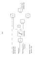
- FIG. 2 is a view showing control logic of the torque control method according to the exemplary embodiment of the present invention.
- FIG. 3 is a flowchart of the torque control method of FIG. 2 .
- vehicle or “vehicular” or other similar term as used herein is inclusive of motor vehicles in general such as passenger automobiles including sports utility vehicles (SUV), buses, trucks, various commercial vehicles, watercraft including a variety of boats and ships, aircraft, and the like, and includes hybrid vehicles, electric vehicles, plug-in hybrid electric vehicles, hydrogen-powered vehicles and other alternative fuel vehicles (e.g., fuels derived from resources other than petroleum).
- a hybrid vehicle is a vehicle that has two or more sources of power, for example both gasoline-powered and electric-powered vehicles.
- the system and method for controlling the torque of the electric motor driven vehicle includes: receiving a current speed of a drive motor, a speed boundary section, a target torque, a drive torque limit and a generation torque limit; calculating a ratio of the current speed in the entire speed boundary section as a mixture ratio when the current speed is within the speed boundary section; calculating a limit torque, reflecting the drive torque limit and the generation torque limit in the calculated mixture ratio; and selecting whichever of the limit torque and the target torque is smaller in absolute value as a final torque that is required of the drive motor.
- a final torque to be generated by the drive motor is input.
- the final torque is determined by taking into account variables, such as a generation torque limit, a drive torque limit determined by a current speed of the electric motor and a SOC (state of charge) of the battery, a target torque determined by a user, etc.
- a command to generate the determined final torque is input to the drive motor.
- a current speed of the drive motor, a speed boundary section, a target torque, a drive torque limit and a generation torque limit are input to a control unit.
- the term “speed boundary section” refers to a speed section in which the control proposed in the present invention is intensively required. The speed boundary section is given in FIG. 1 .
- FIG. 1 is a graph showing a speed boundary section (B) in method and apparatus for controlling torque of an electric motor driven vehicle, according to an embodiment of the present invention.
- the horizontal axis refers to the current speed of the drive motor.
- the vertical axis refers to the target torque of the drive motor.
- the current speed and the target torque have the same sign, it means that the drive motor is in an electric discharge state (a drive state).
- the current speed and the target torque have opposite signs, it means that the drive motor is in a generation state (a charging state).
- the generation or charging state of the drive motor can not precisely be determined based on the sign of the current speed, thus, there may be an error.
- a dark portion in the graph indicates that the drive motor is in the drive state, and around an area in which the current speed is 0, there is generally large variations in the drive torque limit and the generation torque limit.
- the object of the present invention is to prevent the final torque from fluctuating in such a way as to set a speed boundary section around the area of current speed 0 and determine an appropriate torque in response to a ratio of the speed in the section.
- the speed boundary section (B) includes lowest boundary limits L 1 and L 2 and uppermost boundary limits U 1 and U 2 .
- the lowest boundary limit, the uppermost boundary limit and the speed boundary section may be previously set as a predetermined section.
- the current speed of the drive motor, the speed boundary section, the target torque, the drive torque limit and the generation torque limit are input so as to calculate a final torque.
- a general target torque is input to the drive motor as the final torque within the bounds of the drive torque limit and the generation torque limit.
- the term “mixture ratio” refers to a blending ratio for obtaining an appropriate limit torque from blending the drive torque limit with the generation torque limit.
- the mixture ratio is determined based on the position of the current speed in the speed boundary section. In detail, the mixture ratio is determined by dividing the difference between the current speed and the lowest boundary limit by the entire speed boundary section value.
- a limit torque calculation is processed. As a result of this calculation, a limit torque is determined, reflecting the drive torque limit and the generation torque limit depending on the determined mixture ratio.
- the limit torque is determined in such a way that the drive torque limit is reflected in proportion to the difference between the current speed and the lowest boundary limit, and also in such a way that the generation torque limit is reflected in proportion to the difference between the current speed and the uppermost boundary limit.
- the mixture ratio can be calculated by the following equation 1.
- the limit torque can be calculated by the following equation 2.
- final torque MIN(limit torque,
- the smaller value of the two values is selected, and the sign of the target torque is reflected to the selected smaller value, thus obtaining the final torque.
- the drive torque limit and the generation torque limit are always input as absolute values, there is no other choice but to express the limit torque as the absolute value.
- the sign of the target torque is finally reflected in the obtained result.
- the sign of the final torque is determined so that whether the drive motor is in the generation state or the drive state is determined.
- the drive torque limit is blended with the generation torque limit depending on the position of the current speed of the drive motor in the specific speed section which is at issue.
- the value resulting from this blending is then compared with the target torque, and then the smaller of the two values is determined to be the final torque of the drive motor. Therefore, even if the drive torque limit and the generation torque limit are subject to a sudden and large variation, the final torque can be prevented from unstably fluctuating.
- the speed boundary section includes the lowest boundary limit and the uppermost boundary limit
- the mixture ratio can be calculated by dividing the difference between the current speed and the lower boundary limit by the entire speed boundary section value.
- the speed boundary section includes the lowest boundary limit and the uppermost boundary limit
- the mixture ratio calculation step includes calculating the mixture ratio according to the following equation 1.
- final torque MIN(limit torque,
- the speed boundary section includes the lowest boundary limit and the uppermost boundary limit.
- the mixture ratio can be calculated by the following equation 1.
- the limit torque can be calculated by the following equation 2.
- the final torque can be calculated by the following equation 3.
- the current speed of the drive motor, the speed boundary section including the boundary limit and the uppermost boundary limit, the target torque, the drive torque limit and the generation torque limit are input.
- the limit torque is calculated, reflecting the drive torque limit and the generation torque limit depending on the ratio of the current speed in the speed boundary section.
- the torque which has the smaller absolute value is determined as the final torque of the drive motor.
- the limit torque can be obtained, reflecting both the drive torque limit in proportion to the difference between the current speed and the lowest boundary limit, and the generation torque limit in proportion to the difference between the current speed and the uppermost boundary limit.
- the torque control apparatus for the electric motor driven vehicle using the above-mentioned torque control method includes a drive motor and a control unit.
- the drive motor provides drive force to the vehicle.
- the control unit calculates a final torque required of the drive motor using the current speed of the drive motor, a speed boundary section including a lowest boundary limit and an uppermost boundary limit, a target torque, a drive torque limit and a generation torque limit.
- the control unit calculates a limit torque, reflecting the drive torque limit and the generation torque limit in response to a ratio of the current speed in the speed boundary section. Of the limit torque and the target torque, the control unit determines the torque that has the smaller absolute value as the final torque required of the drive motor.
- control unit calculates the limit torque, reflecting both the drive torque limit in proportion to a difference between the current speed and the lowest boundary limit, and the generation torque limit in proportion to a difference between the current speed and the uppermost boundary limit.
- the present invention may be embodied as computer readable media on a computer readable medium containing executable program instructions executed by a processor, controller or the like, for example a motor control unit.
- the computer readable mediums include, but are not limited to, ROM, RAM, compact disc (CD)-ROMs, magnetic tapes, floppy disks, flash drives, smart cards and optical data storage devices.
- the computer readable recording medium can also be distributed in network coupled computer systems, such as a telematics system, so that the computer readable media is stored and executed in a distributed fashion.
- the limit torque is determined from between the drive torque limit and the generation torque limit.
- the speed rather than the torque is the criteria for the determination of the limit torque.
- an additional control method in addition to the conventional final torque control method can be used so that the final torque is generally linearly controlled.
Landscapes
- Engineering & Computer Science (AREA)
- Transportation (AREA)
- Mechanical Engineering (AREA)
- Chemical & Material Sciences (AREA)
- Combustion & Propulsion (AREA)
- Power Engineering (AREA)
- Automation & Control Theory (AREA)
- Electric Propulsion And Braking For Vehicles (AREA)
Abstract
Description
limit torque=(mixture ratio×drive torque limit value)+(1−mixture ratio)×(generation torque limit value)
final torque=MIN(limit torque,|target torque|)×sign(target torque).
final torque=MIN(limit torque,|target torque|)×sign(target torque) Equation 3
limit torque=(mixture ratio×drive torque limit value)+(1−mixture ratio)×(generation torque limit value) Equation 2
final torque=MIN(limit torque,|target torque|)×sign(target torque) Equation 3
Claims (12)
limit torque=(mixture ratio×drive torque limit value)+(1−mixture ratio)×(generation torque limit value).
final torque=MIN(limit torque,|target torque|)×sgn(target torque)
limit torque=(mixture ratio×drive torque limit value)+(1−mixture ratio)×(generation torque limit value) Equation 2
final torque=MIN(limit torque,|target torque|)=sgn(target torque) Equation 3
limit torque=(mixture ratio×drive torque limit value)+(1−mixture ratio)×(generation torque limit value).
final torque=MIN(limit torque,|target torque|)×sgn(target torque)
limit torque=(mixture ratio×drive torque limit value)+(1−mixture ratio)×(generation torque limit value)
final torque=MIN(limit torque,|target torque|)×sgn(target torque)
Applications Claiming Priority (2)
| Application Number | Priority Date | Filing Date | Title |
|---|---|---|---|
| KR10-2011-0049156 | 2011-05-24 | ||
| KR1020110049156A KR101284293B1 (en) | 2011-05-24 | 2011-05-24 | Method and system for controlling torque of motor drive vehicle |
Publications (2)
| Publication Number | Publication Date |
|---|---|
| US20120299518A1 US20120299518A1 (en) | 2012-11-29 |
| US8610390B2 true US8610390B2 (en) | 2013-12-17 |
Family
ID=47140260
Family Applications (1)
| Application Number | Title | Priority Date | Filing Date |
|---|---|---|---|
| US13/297,585 Active 2032-06-05 US8610390B2 (en) | 2011-05-24 | 2011-11-16 | Method and apparatus for controlling torque of an electric motor driven vehicle |
Country Status (5)
| Country | Link |
|---|---|
| US (1) | US8610390B2 (en) |
| JP (1) | JP5745376B2 (en) |
| KR (1) | KR101284293B1 (en) |
| CN (1) | CN102795120B (en) |
| DE (1) | DE102011087412B4 (en) |
Families Citing this family (2)
| Publication number | Priority date | Publication date | Assignee | Title |
|---|---|---|---|---|
| KR101944485B1 (en) * | 2016-08-24 | 2019-02-01 | 주식회사 브이씨텍 | Speed control apparatus for low speed electric vehicle |
| CN114312350B (en) * | 2022-01-05 | 2023-07-14 | 一汽解放汽车有限公司 | Motor control method, device, computer equipment and storage medium |
Citations (7)
| Publication number | Priority date | Publication date | Assignee | Title |
|---|---|---|---|---|
| US5905349A (en) * | 1998-04-23 | 1999-05-18 | Ford Motor Company | Method of controlling electric motor torque in an electric vehicle |
| JP2007274781A (en) | 2006-03-30 | 2007-10-18 | Aisin Aw Co Ltd | Electric drive control device and electric drive control method |
| US20070278021A1 (en) * | 2006-04-25 | 2007-12-06 | Ekkehard Pott | Method for controlling the torque of a hybrid drive unit and hybrid drive unit |
| JP2007326411A (en) | 2006-06-06 | 2007-12-20 | Hitachi Constr Mach Co Ltd | Drive system of power-driven dump truck |
| US7345443B2 (en) * | 2004-03-26 | 2008-03-18 | Kabushiki Kaisha Yaskawa Denki | Motor control apparatus |
| US20090321166A1 (en) * | 2006-03-21 | 2009-12-31 | Jens-Werner Falkenstein | Method for operating a hybrid drive for a vehicle |
| US20100286855A1 (en) * | 2007-09-30 | 2010-11-11 | Chery Automobile Co., Ltd | Torque management method for hybrid electric motor |
Family Cites Families (11)
| Publication number | Priority date | Publication date | Assignee | Title |
|---|---|---|---|---|
| KR100448365B1 (en) * | 2001-12-18 | 2004-09-10 | 현대자동차주식회사 | Motor control method of fuel cell electric vehicle |
| JP3985550B2 (en) * | 2002-02-28 | 2007-10-03 | アイシン・エィ・ダブリュ株式会社 | Electric vehicle drive control device, electric vehicle drive control method, and program thereof |
| JP3610969B2 (en) * | 2002-08-27 | 2005-01-19 | 日産自動車株式会社 | Driving force control device for four-wheel drive vehicle |
| KR100534683B1 (en) * | 2002-09-05 | 2005-12-07 | 현대자동차주식회사 | Method of protecting a shock of the motor in a hybrid vehicle |
| US7024299B2 (en) | 2004-05-15 | 2006-04-04 | General Motors Corporation | Method for dynamically determining peak output torque within battery constraints in a hybrid transmission including a parallel hybrid split |
| JP4783580B2 (en) * | 2005-03-31 | 2011-09-28 | 本田技研工業株式会社 | Fuel cell electrical system, fuel cell vehicle and power supply method |
| JP4696918B2 (en) * | 2006-01-10 | 2011-06-08 | トヨタ自動車株式会社 | Vehicle control device |
| JP4424335B2 (en) * | 2006-07-18 | 2010-03-03 | トヨタ自動車株式会社 | Control device for hybrid vehicle |
| US7459874B2 (en) | 2007-02-20 | 2008-12-02 | Gm Global Technology Operations, Inc. | System and method for controlling electric drive systems |
| JP5412719B2 (en) * | 2007-10-22 | 2014-02-12 | トヨタ自動車株式会社 | Vehicle control device with fuel cell |
| US8405335B2 (en) * | 2007-12-28 | 2013-03-26 | Aisin Aw Co., Ltd. | Rotary electric machine control system |
-
2011
- 2011-05-24 KR KR1020110049156A patent/KR101284293B1/en active Active
- 2011-09-26 JP JP2011208895A patent/JP5745376B2/en active Active
- 2011-11-16 US US13/297,585 patent/US8610390B2/en active Active
- 2011-11-30 CN CN201110391007.7A patent/CN102795120B/en active Active
- 2011-11-30 DE DE102011087412.7A patent/DE102011087412B4/en active Active
Patent Citations (7)
| Publication number | Priority date | Publication date | Assignee | Title |
|---|---|---|---|---|
| US5905349A (en) * | 1998-04-23 | 1999-05-18 | Ford Motor Company | Method of controlling electric motor torque in an electric vehicle |
| US7345443B2 (en) * | 2004-03-26 | 2008-03-18 | Kabushiki Kaisha Yaskawa Denki | Motor control apparatus |
| US20090321166A1 (en) * | 2006-03-21 | 2009-12-31 | Jens-Werner Falkenstein | Method for operating a hybrid drive for a vehicle |
| JP2007274781A (en) | 2006-03-30 | 2007-10-18 | Aisin Aw Co Ltd | Electric drive control device and electric drive control method |
| US20070278021A1 (en) * | 2006-04-25 | 2007-12-06 | Ekkehard Pott | Method for controlling the torque of a hybrid drive unit and hybrid drive unit |
| JP2007326411A (en) | 2006-06-06 | 2007-12-20 | Hitachi Constr Mach Co Ltd | Drive system of power-driven dump truck |
| US20100286855A1 (en) * | 2007-09-30 | 2010-11-11 | Chery Automobile Co., Ltd | Torque management method for hybrid electric motor |
Also Published As
| Publication number | Publication date |
|---|---|
| JP5745376B2 (en) | 2015-07-08 |
| US20120299518A1 (en) | 2012-11-29 |
| DE102011087412B4 (en) | 2021-12-16 |
| CN102795120A (en) | 2012-11-28 |
| KR101284293B1 (en) | 2013-07-08 |
| KR20120131001A (en) | 2012-12-04 |
| JP2012244894A (en) | 2012-12-10 |
| DE102011087412A1 (en) | 2012-11-29 |
| CN102795120B (en) | 2016-05-04 |
Similar Documents
| Publication | Publication Date | Title |
|---|---|---|
| US9469302B2 (en) | Torque control apparatus and method and motor controller | |
| US8718914B2 (en) | Method and device for providing eco-driving information | |
| US9908420B2 (en) | Charging control method and system for electric vehicle | |
| US9168916B2 (en) | Method and system for controlling acceleration torque of hybrid vehicle | |
| US10000202B2 (en) | Device and method for controlling running mode of hybrid electric vehicle | |
| US9481371B2 (en) | Method and apparatus for controlling speed change of hybrid vehicle | |
| US9527389B2 (en) | System and method for estimating allowable regenerative braking of vehicle | |
| EP2889179B1 (en) | Control method and system of electric vehicle | |
| EP3138750B1 (en) | Engine operation control system and method of eco-friendly vehicle | |
| CN108609009B (en) | Method for controlling deceleration of vehicle using vehicle travel information | |
| US9789866B2 (en) | Apparatus and method for controlling mode change of hybrid electric vehicle | |
| US11014456B2 (en) | System and method for reducing acceleration shock of electric motor vehicle | |
| US9707848B2 (en) | Braking control method for eco-friendly vehicle | |
| US8907613B2 (en) | System and method for controlling motor of electric vehicle | |
| US9481362B2 (en) | Driving control apparatus and method for hybrid vehicle | |
| US10576960B2 (en) | Apparatus and method for calculating maximum output torque of engine of hybrid electric vehicle | |
| US20150005999A1 (en) | System and method for controlling driving mode of hybrid vehicle | |
| US8610390B2 (en) | Method and apparatus for controlling torque of an electric motor driven vehicle | |
| US20170297439A1 (en) | Method and system for controlling vehicle converter | |
| US11491881B2 (en) | Method and system for guiding accelerator pedal of electric vehicle | |
| US10759414B2 (en) | Driving control method for hybrid vehicle | |
| EP2985171B1 (en) | Forced charging method for phev vehicles using motor and hsg | |
| US11827208B2 (en) | Driving guide setting system of electric operating vehicle and method of setting the driving guide | |
| US9610952B2 (en) | Apparatus and method for controlling creep torque of a vehicle | |
| KR102360170B1 (en) | Apparatus and method for drive controlling of hybrid vehicle |
Legal Events
| Date | Code | Title | Description |
|---|---|---|---|
| AS | Assignment |
Owner name: KIA MOTORS CORPORATION, KOREA, REPUBLIC OF Free format text: ASSIGNMENT OF ASSIGNORS INTEREST;ASSIGNOR:PARK, JOON YOUNG;REEL/FRAME:027236/0516 Effective date: 20111021 Owner name: HYUNDAI MOTOR COMPANY, KOREA, REPUBLIC OF Free format text: ASSIGNMENT OF ASSIGNORS INTEREST;ASSIGNOR:PARK, JOON YOUNG;REEL/FRAME:027236/0516 Effective date: 20111021 |
|
| FEPP | Fee payment procedure |
Free format text: PAYOR NUMBER ASSIGNED (ORIGINAL EVENT CODE: ASPN); ENTITY STATUS OF PATENT OWNER: LARGE ENTITY |
|
| STCF | Information on status: patent grant |
Free format text: PATENTED CASE |
|
| FEPP | Fee payment procedure |
Free format text: PAYOR NUMBER ASSIGNED (ORIGINAL EVENT CODE: ASPN); ENTITY STATUS OF PATENT OWNER: LARGE ENTITY Free format text: PAYER NUMBER DE-ASSIGNED (ORIGINAL EVENT CODE: RMPN); ENTITY STATUS OF PATENT OWNER: LARGE ENTITY |
|
| FPAY | Fee payment |
Year of fee payment: 4 |
|
| MAFP | Maintenance fee payment |
Free format text: PAYMENT OF MAINTENANCE FEE, 8TH YEAR, LARGE ENTITY (ORIGINAL EVENT CODE: M1552); ENTITY STATUS OF PATENT OWNER: LARGE ENTITY Year of fee payment: 8 |
|
| MAFP | Maintenance fee payment |
Free format text: PAYMENT OF MAINTENANCE FEE, 12TH YEAR, LARGE ENTITY (ORIGINAL EVENT CODE: M1553); ENTITY STATUS OF PATENT OWNER: LARGE ENTITY Year of fee payment: 12 |